WO2012132649A1 - 凹凸シート及びその製造方法 - Google Patents
凹凸シート及びその製造方法 Download PDFInfo
- Publication number
- WO2012132649A1 WO2012132649A1 PCT/JP2012/054217 JP2012054217W WO2012132649A1 WO 2012132649 A1 WO2012132649 A1 WO 2012132649A1 JP 2012054217 W JP2012054217 W JP 2012054217W WO 2012132649 A1 WO2012132649 A1 WO 2012132649A1
- Authority
- WO
- WIPO (PCT)
- Prior art keywords
- sheet
- convex
- concavo
- tall
- resin
- Prior art date
- Legal status (The legal status is an assumption and is not a legal conclusion. Google has not performed a legal analysis and makes no representation as to the accuracy of the status listed.)
- Ceased
Links
Images




Classifications
-
- B—PERFORMING OPERATIONS; TRANSPORTING
- B29—WORKING OF PLASTICS; WORKING OF SUBSTANCES IN A PLASTIC STATE IN GENERAL
- B29C—SHAPING OR JOINING OF PLASTICS; SHAPING OF MATERIAL IN A PLASTIC STATE, NOT OTHERWISE PROVIDED FOR; AFTER-TREATMENT OF THE SHAPED PRODUCTS, e.g. REPAIRING
- B29C43/00—Compression moulding, i.e. applying external pressure to flow the moulding material; Apparatus therefor
- B29C43/22—Compression moulding, i.e. applying external pressure to flow the moulding material; Apparatus therefor of articles of indefinite length
- B29C43/222—Compression moulding, i.e. applying external pressure to flow the moulding material; Apparatus therefor of articles of indefinite length characterised by the shape of the surface
-
- B—PERFORMING OPERATIONS; TRANSPORTING
- B29—WORKING OF PLASTICS; WORKING OF SUBSTANCES IN A PLASTIC STATE IN GENERAL
- B29C—SHAPING OR JOINING OF PLASTICS; SHAPING OF MATERIAL IN A PLASTIC STATE, NOT OTHERWISE PROVIDED FOR; AFTER-TREATMENT OF THE SHAPED PRODUCTS, e.g. REPAIRING
- B29C48/00—Extrusion moulding, i.e. expressing the moulding material through a die or nozzle which imparts the desired form; Apparatus therefor
- B29C48/03—Extrusion moulding, i.e. expressing the moulding material through a die or nozzle which imparts the desired form; Apparatus therefor characterised by the shape of the extruded material at extrusion
- B29C48/07—Flat, e.g. panels
- B29C48/08—Flat, e.g. panels flexible, e.g. films
-
- B—PERFORMING OPERATIONS; TRANSPORTING
- B29—WORKING OF PLASTICS; WORKING OF SUBSTANCES IN A PLASTIC STATE IN GENERAL
- B29C—SHAPING OR JOINING OF PLASTICS; SHAPING OF MATERIAL IN A PLASTIC STATE, NOT OTHERWISE PROVIDED FOR; AFTER-TREATMENT OF THE SHAPED PRODUCTS, e.g. REPAIRING
- B29C48/00—Extrusion moulding, i.e. expressing the moulding material through a die or nozzle which imparts the desired form; Apparatus therefor
- B29C48/03—Extrusion moulding, i.e. expressing the moulding material through a die or nozzle which imparts the desired form; Apparatus therefor characterised by the shape of the extruded material at extrusion
- B29C48/12—Articles with an irregular circumference when viewed in cross-section, e.g. window profiles
-
- G—PHYSICS
- G02—OPTICS
- G02B—OPTICAL ELEMENTS, SYSTEMS OR APPARATUS
- G02B3/00—Simple or compound lenses
- G02B3/0006—Arrays
- G02B3/0012—Arrays characterised by the manufacturing method
- G02B3/0031—Replication or moulding, e.g. hot embossing, UV-casting, injection moulding
-
- G—PHYSICS
- G02—OPTICS
- G02B—OPTICAL ELEMENTS, SYSTEMS OR APPARATUS
- G02B3/00—Simple or compound lenses
- G02B3/0006—Arrays
- G02B3/0037—Arrays characterized by the distribution or form of lenses
- G02B3/0043—Inhomogeneous or irregular arrays, e.g. varying shape, size, height
-
- G—PHYSICS
- G02—OPTICS
- G02B—OPTICAL ELEMENTS, SYSTEMS OR APPARATUS
- G02B3/00—Simple or compound lenses
- G02B3/0006—Arrays
- G02B3/0037—Arrays characterized by the distribution or form of lenses
- G02B3/005—Arrays characterized by the distribution or form of lenses arranged along a single direction only, e.g. lenticular sheets
-
- B—PERFORMING OPERATIONS; TRANSPORTING
- B29—WORKING OF PLASTICS; WORKING OF SUBSTANCES IN A PLASTIC STATE IN GENERAL
- B29C—SHAPING OR JOINING OF PLASTICS; SHAPING OF MATERIAL IN A PLASTIC STATE, NOT OTHERWISE PROVIDED FOR; AFTER-TREATMENT OF THE SHAPED PRODUCTS, e.g. REPAIRING
- B29C48/00—Extrusion moulding, i.e. expressing the moulding material through a die or nozzle which imparts the desired form; Apparatus therefor
- B29C48/001—Combinations of extrusion moulding with other shaping operations
- B29C48/0011—Combinations of extrusion moulding with other shaping operations combined with compression moulding
-
- B—PERFORMING OPERATIONS; TRANSPORTING
- B29—WORKING OF PLASTICS; WORKING OF SUBSTANCES IN A PLASTIC STATE IN GENERAL
- B29C—SHAPING OR JOINING OF PLASTICS; SHAPING OF MATERIAL IN A PLASTIC STATE, NOT OTHERWISE PROVIDED FOR; AFTER-TREATMENT OF THE SHAPED PRODUCTS, e.g. REPAIRING
- B29C48/00—Extrusion moulding, i.e. expressing the moulding material through a die or nozzle which imparts the desired form; Apparatus therefor
- B29C48/25—Component parts, details or accessories; Auxiliary operations
- B29C48/88—Thermal treatment of the stream of extruded material, e.g. cooling
- B29C48/911—Cooling
- B29C48/9135—Cooling of flat articles, e.g. using specially adapted supporting means
- B29C48/914—Cooling drums
-
- B—PERFORMING OPERATIONS; TRANSPORTING
- B29—WORKING OF PLASTICS; WORKING OF SUBSTANCES IN A PLASTIC STATE IN GENERAL
- B29L—INDEXING SCHEME ASSOCIATED WITH SUBCLASS B29C, RELATING TO PARTICULAR ARTICLES
- B29L2011/00—Optical elements, e.g. lenses, prisms
- B29L2011/0016—Lenses
- B29L2011/005—Fresnel lenses
Definitions
- the present invention relates to a concavo-convex sheet and a method for manufacturing the concavo-convex sheet, and particularly relates to a concavo-convex sheet in which a concavo-convex pattern serving as a lens is formed on one surface of the sheet and wound in a roll shape in the manufacturing process, and a method for manufacturing the concavo-convex sheet.
- Fresnel lenses, lenticular lenses, etc. as resin concavo-convex sheets used for various optical elements, and they are used in various fields.
- a regular concavo-convex pattern serving as a lens is formed on the surface of the concavo-convex sheet, and the optical performance is exhibited by the concavo-convex pattern.
- an extrusion molding method, an extrusion laminating method, and a 2P method are generally used as a method for producing such a concavo-convex sheet.
- a belt-shaped resin sheet obtained by extruding a thermoplastic molten resin into a sheet shape from an extrusion die is nipped between a mold roller and a nip roller, and the inverted shape of the uneven pattern formed on the mold roller is transferred to the resin sheet. Then, the transferred resin sheet is peeled off from the mold roller. And the strip
- the extrusion laminating method is a method of laminating a belt-like substrate as a support on a resin sheet extruded from an extrusion die, and the other is the same as the extrusion molding method.
- UV (ultraviolet) curable resin is applied to a support, then wrapped on a mold roller, and irradiated with UV light while being wrapped, the inverted pattern of the concavo-convex pattern formed on the mold roller is resin
- the transferred resin sheet is peeled off from the mold roller. And it is the method of winding up the peeled strip
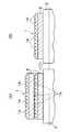
- the uneven sheet 2 having the uneven pattern 1 formed on the sheet surface is wound by the winding device as shown in FIG.
- the convex portion 1 ⁇ / b> A of the concave / convex pattern 1 is crushed as shown by a portion 8 ⁇ / b> B in the drawing due to the winding pressure due to the winding tension, and the optical performance is not exhibited.
- Patent Document 1 discloses a technique for performing a knurling process in which a large number of spherical protrusions are formed at both ends in the film width direction, thereby preventing winding slippage during winding. .
- Patent Document 2 introduces an improved technique of Patent Document 1. That is, as disclosed in Patent Document 1, since the spherical protrusions are not sufficiently formed even if the knurling process is performed on the film that has not been softened after being manufactured, the embossing roller is applied to the film that is soft when the film is extruded. It is proposed to do the knurling process.
- Patent Documents 1 and 2 do not have a problem of preventing the protrusions of the concavo-convex pattern formed on the sheet surface from being crushed when winding the concavo-convex sheet into a roll, and are based on countermeasures for solving the problem. It is not done.
- the present invention has been made in view of such circumstances, and since the concave / convex pattern is not crushed even when wound up in a roll shape, the original function of the concave / convex pattern such as optical performance can be exhibited.
- An object is to provide an uneven sheet and a method for producing the same.
- the uneven sheet of the present invention has an uneven pattern formed on a belt-like sheet surface and is wound into a roll shape, and the sheet is provided on at least both ends in the width direction of the sheet surface.
- a tall ridge that is taller than the projection of the concavo-convex pattern is formed along the longitudinal direction.
- tall ridges that are taller than the convex portions of the concavo-convex pattern are formed along the longitudinal direction of the sheet at least at both ends in the width direction of the belt-shaped sheet surface. Therefore, when winding the uneven sheet into a roll, the tall ridges serve as bridge girders that bridge the uneven sheet to be wound next.
- the winding pressure of the winding tension for winding the concavo-convex sheet in a roll shape can be supported by the tall convex ridges.
- the winding pressure applied compared with the case where there is no high convex part can be made remarkably small.
- the concavo-convex pattern formed on the sheet surface is not crushed, so that the original function of the concavo-convex pattern such as optical performance can be exhibited.
- the present invention is not limited to the formation of one tall ridge at each of at least both ends in the width direction of the seat surface.
- line part can be strengthened.
- the tall ridge is 1.2 to 2.5 times as high as the ridge of the concavo-convex pattern before being wound into the roll.
- the tall ridges are also crushed to some extent by the winding pressure, but with a normal winding tension (200 to 700 N / support width), the tall ridges are 1.2 times or more of the protrusions of the concavo-convex pattern. If so, the convex portion can be protected so as not to lose the original function of the concave-convex pattern such as optical performance.
- the tall convex part is larger than 2.5 times the convex part of the concave / convex pattern, not only the final winding diameter becomes too large but also an air layer is formed between the wound concave / convex sheets. It becomes easy to be done. Then, due to the formation of this air layer, winding deviation occurs, or winding collapse occurs during handling. Therefore, the height of the tall convex portion is preferably in the range of 1.2 to 2.5 times the convex portion of the concave / convex pattern.
- the concavo-convex sheet of the present invention is partitioned into a plurality of product regions in which the concavo-convex pattern is formed at intervals in the sheet width direction, and also in a non-product region between the product regions. It is preferable that the tall ridge is formed.
- notches are formed in the tall ridges at regular intervals.
- the method for producing a concavo-convex sheet according to the present invention is a method for producing a concavo-convex sheet in which a concavo-convex pattern is formed on a sheet surface, by extruding a thermoplastic molten resin into a sheet form from an extrusion die.
- An extrusion process for forming a resin sheet, and a reverse shape of the concave / convex pattern is formed on the roller surface, and at least at both ends in the width direction of the roller surface along the circumferential direction of the roller than the convex portion of the concave / convex pattern.
- the resin sheet extruded from the extrusion die is nipped by the rotating mold roller and the nip roller, and the uneven pattern is formed on the resin sheet surface.
- the step of transferring the tall ridges at the same time and then cooling and solidifying the resin sheet, and peeling the resin sheet after the transfer step from the mold roller A peeling step, and a winding step for winding into a roll of the resin sheet after the peeling process.
- the concavo-convex sheet when transferring the concavo-convex pattern to the resin sheet, at least both ends in the resin sheet width direction are taller than the convex part of the concavo-convex pattern along the longitudinal direction of the resin sheet. High ridges were transferred. Thereby, even if an uneven
- the concavo-convex pattern and the tall ridges are simultaneously transferred onto the resin sheet surface using a mold roller in which the concavo-convex pattern and the tall ridges are reversed, so only the mold roller is transferred. If it changes, the manufacturing line of the uneven
- the production method of the present invention includes a laminating step of laminating the resin sheet extruded from the extrusion die on the surface of the belt-like substrate having a rigidity higher than that of the resin sheet between the extrusion step and the transfer step. It is preferable.
- the present invention can also be applied to a method for producing a concavo-convex sheet by an extrusion lamination method. Further, by laminating a resin sheet on a belt-like base material having a rigidity higher than that of the resin sheet by the extrusion laminating method, the rigidity of the manufactured uneven sheet becomes stronger than that of the resin sheet alone. Thereby, when a concavo-convex sheet is wound up in a roll shape, the concavo-convex sheet becomes difficult to bend between tall ridges, so that the role of the tall ridges as a bridge girder can be further enhanced. If the rugged sheet is stiff and the rugged sheet bends between the tall ridges, the rugged pattern near the tall ridges will not be crushed, but the rugged pattern farther away from the tall ridges will be crushed easily. .
- the concavo-convex sheet is partitioned into a plurality of product regions in which the concavo-convex pattern is formed at intervals in the width direction, and also in a non-product region between the product regions. It is preferable to form a tall ridge.
- the tall ridges are projected by the winding pressure of the winding pattern. It is preferable to set the height of the tall convex portion according to the winding tension so as to be crushed to substantially the same height as the portion.
- the height of the tall convex portion is set according to the winding tension so that the tall convex strip is crushed to the same height as the convex portion of the uneven pattern by the winding pressure of the winding tension, Moreover, it can also suppress that a winding pressure is added to the convex part of an uneven
- the extent to which the tall ridges are crushed by the winding tension can be known in advance by a preliminary test or the like, and based on the result, the projections of the inverted concavo-convex pattern formed on the mold roller
- the relationship between the corresponding depth (corresponding to the height of the convex portion) and the depth corresponding to the tall convex portion (corresponding to the height of the tall convex portion) can be determined.
- the concavo-convex pattern is a lenticular lens formed in the longitudinal direction of the resin sheet, and the tall ridge and the concavo-convex pattern are different only in height.
- the shape is preferred.
- the inverted shape of the tall ridges and the concavo-convex pattern is formed on the mold roller. In doing so, it is only necessary to change the depth of the inverted shape. Therefore, no special work is required for manufacturing the mold roller.
- the inverted shape of the tall ridge formed on the roller surface of the mold roller is a cut having a different shape at regular intervals of the tall ridge transferred to the resin sheet. It is preferable to have a reversed shape in which a notch is formed.
- the concavo-convex pattern is not crushed even when it is wound up in a roll shape.
- FIG. 1 is a schematic diagram of a manufacturing apparatus 10 that performs a manufacturing method of a concavo-convex sheet in an embodiment of the present invention, and shows a case where an extrusion laminating method in which a resin sheet is laminated on a belt-like substrate is applied.
- this invention is applicable also to the extrusion method which does not have a strip
- the dried thermoplastic raw material resin is put into an extruder 14 through a hopper 12 and melted while being kneaded.
- the extruder 14 may be either a single-screw extruder or a multi-screw extruder, and may include a vent function that evacuates the interior of the extruder 14.
- the extrusion die 18 mainly includes a manifold 18A that spreads the molten resin sent from the extruder 14 in the die width direction, and a slit 18B that is a narrow flow path and extrudes the spread molten resin in a sheet shape to the outside. It consists of.
- the resin sheet 20 extruded in a sheet shape from the slit 18B of the extrusion die 18 is supplied to the nip point P between the mold roller 26 and the nip roller 28 that rotate in the arrow direction.
- the nip roller 28 may be driven to rotate in synchronization with the mold roller 26, and may be driven to rotate by the mold roller 26.
- the belt-like base material 24 is fed from the feeding device 22 and supplied to the nip point P so as to sandwich the resin sheet 20 with the mold roller 26.
- the resin sheet 20 is laminated on the surface of the belt-like base material 24, and the belt-like base material 24 on which the resin sheet 20 is laminated is nipped by the mold roller 26 and the nip roller 28.
- the resin sheet 20 can be firmly laminated on the surface of the belt-like substrate 24 by the adhesive resin layer.
- an extruder for melting the adhesive resin layer is not shown.
- the roller surface of the mold roller 26 is formed with an inverted shape 32 of the concavo-convex pattern 30 transferred to the resin sheet 20, and the roller surface.
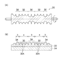
- Inverted shapes 36 of the tall ridges 34 that are taller than the protrusions 30A of the concavo-convex pattern 30 along the roller circumferential direction (rotational direction) at least at both ends in the width direction (corresponding to both ends of the resin sheet 20). It is formed.
- FIG. 2 shows the case where the resin sheet 20 is partitioned into two product regions a in which the concave / convex pattern 30 is formed at intervals in the width direction of the resin sheet 20.
- the inverted shape 36 is formed on the mold roller 26 so that the tall ridges 34 are also formed in the non-product region b between the width direction both ends of the resin sheet 20 and the product region a.
- the A cooling means (not shown) for keeping the roller surface at a low temperature is provided inside the mold roller 26.
- the inverted shapes 32 and 36 of the mold roller 26 are transferred to the surface of the resin sheet 20.
- Concave and convex patterns 30 and tall ridges 34 are formed on the surface.
- the resin sheet 20 that contacts the roller surface of the mold roller 26 is cooled and solidified while the belt-shaped substrate 24 is conveyed from the nip point P to the peeling roller 38 (see FIG. 1) as the mold roller 26 rotates. Then, the transferred concavo-convex pattern 30 and the tall ridge 34 are fixed.
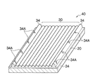
- an uneven sheet 40 including, for example, a lenticular lens is formed as the uneven pattern 30.
- a lenticular lens it is preferable to provide the lenticular lens on the surface where the thickness of the entire resin sheet is in the range of 50 to 300 ⁇ m.
- the shape of the lenticular lens is preferably formed with a radius of curvature (R) of 100 to 200 ⁇ m, a lens height (H) of 30 to 100 ⁇ m, and a span (S) of 100 to 318 ⁇ m.
- FIG. 3 an example in which the tall ridges 34 are formed only at both ends of the resin sheet 20 is shown. And as shown in FIG. 1, the uneven
- FIG. 4A is a conceptual diagram in which the concavo-convex sheet 40 is wound in a roll shape
- FIG. 4B is a cross-sectional view taken along the line AA of FIG. 4A. It is.
- corrugated sheet 40 should actually be wound in the shape of a spiral, in (A) part of FIG. 4, it is simplified and the roll shape is drawn concentrically.
- the dark color part of the (A) part of FIG. 4 is the strip
- the tall ridge 34 formed on the concavo-convex sheet 40A on the first turn of the winding is It contacts the back surface (band-like base material 24) of the concavo-convex sheet 40B in the second turn of the winding and serves as a bridge girder that bridges the concavo-convex sheet 40B in the second turn of the winding.
- the tall ridge 34 formed on the concavo-convex sheet 40B on the second turn of the winding contacts the back surface of the concavo-convex sheet 40C on the third lap of winding, and bridges the concavo-convex sheet 40C on the third turn of the winding.
- the concavo-convex sheet 40 is wound while repeating this crosslinking action.
- the winding pressure of the winding tension for winding the concavo-convex sheet 40 in a roll shape can be supported by the tall ridge 34, the winding pressure is not applied to the ridge 30A of the concavo-convex pattern 30 or is added. Even if it is, the winding pressure added compared with the case where there is no tall convex part 34 can be made remarkably small. As a result, even if the concavo-convex sheet 40 is wound up in a roll shape, the concavo-convex pattern 30 formed on the sheet surface is not crushed, so that the original function of the concavo-convex pattern such as optical performance can be exhibited.
- the manufactured uneven sheet 40 has only the resin sheet 20 having rigidity. Be stronger than the case.
- corrugated sheet 40 is wound up in roll shape, the uneven
- the uneven sheet 40 is bent between the tall ridges 34 with low rigidity, the concavo-convex pattern 30 near the tall ridges 34 is not crushed but separated from the tall ridges 34. The uneven pattern 30 is easily crushed.
- the tall ridge 34 is crushed to the same height as the convex 30A of the concavo-convex pattern 30 by the winding pressure of the winding tension.
- the height of the high ridge 34 is set. In this case, the height of the tall ridge 34 can be determined by actually conducting a preliminary winding test, but it can also be determined offline by measuring the winding pressure due to the winding tension.
- a resin material used for the resin sheet 20 is molded with a convex resin having the same diameter as the tall ridge 34 and a predetermined length (for example, 10 cm), and a load corresponding to the measured winding pressure is applied to the convex resin.
- the degree to which the convex resin is crushed is measured. Then, a value obtained by adding the crushed distance to the height of the convex portion 30 ⁇ / b> A of the concave / convex pattern 30 is defined as the height of the tall convex portion 34.
- the height of the tall ridge 34 is simply within a range of 1.2 to 2.5 times the height of the convex 30A of the concavo-convex pattern 30. The effect can be obtained even if the height of the high ridge 34 is set. If the tall ridge 34 is at least 1.2 times the height 30A of the concavo-convex pattern 30, the ridge 30A can be protected so as not to lose the original function of the concavo-convex pattern such as optical performance. In addition, when the tall ridge 34 is larger than 2.5 times the protrusion 30A of the concavo-convex pattern 30, not only the final winding diameter becomes too large, but also between the concavo-convex sheets 40 wound together. An air layer is easily formed. Then, due to the formation of this air layer, winding deviation occurs, or winding collapse occurs during handling.
- notches 34 ⁇ / b> A in the tall ridge 34 at regular intervals.
- the accompanying air can be escaped from the notches 34A, so that it is possible to prevent the occurrence of winding deviation and slow winding.
- the notch 34A having a different shape includes not only the case where the shape of the shape is different, but also the depth and width of the notch 34A being different. In short, it is only necessary to visually identify the notches 34A. Moreover, it is not limited to the shape being different for all of the cutouts 34A formed in the tall ridge 34, and the case where a plurality of cutouts 34A having different shapes are taken as one unit is included. .
- the inverted shape 32 of the high-precision concavo-convex pattern 30 is formed on the roller surface of the mold roller 26, as described above. Therefore, there is a concern that when the dirt attached to the roller surface is wiped with a solvent or the like, the concavo-convex pattern 30 may be damaged.
- FIG. 5 shows a case where notches 34 ⁇ / b> A having different depths are formed at intervals of 90 ° in the circumferential angle of the mold roller 26.
- the strip-shaped uneven pattern 30 is not used as an optical element as it is, but is unwound from the winding device 42 and conveyed to a punching process (not shown).
- the uneven sheet 40 is punched into a predetermined size (for example, 12.7 cm ⁇ 17.8 cm).
- a predetermined size for example, 12.7 cm ⁇ 17.8 cm.
- accurate punching can be performed by using, as a reference line, the tall ridge 34 that is parallel to the ridge line of the lenticular lens and is higher than the height of the lenticular lens and easily becomes a target.
- the concave / convex pattern 30 is not crushed even if it is wound in a roll shape, the original function of the concave / convex pattern such as optical performance can be exhibited. Further, as a secondary effect of the tall ridge 34, it can be used as a reference position for specifying the position of the mold roller dirt and punching.
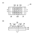
- the example of the lenticular lens has been described as an example of the concavo-convex pattern 30, but as shown in FIGS. 6A and 6B, the quadrangular pyramidal convex portions 30A are formed in a lattice shape.
- the uneven pattern 30 may be used.
- the height H of the quadrangular pyramidal projections 30A is in the range of 20 to 50 ⁇ m and the span S is in the range of 10 to 100 ⁇ m.
- the belt-like substrate 24, the resin sheet 20, the adhesive resin layer, the extrusion die 18 of the manufacturing apparatus 10, and the rollers 26, 28, and 38 in the present embodiment will be described.
- the belt-like substrate 24 has a surface as smooth as possible and is larger than the rigidity of the resin sheet 20 to be laminated. Moreover, when the uneven
- the strip-shaped substrate 24 preferably has a thickness of 100 ⁇ m to 300 ⁇ m, and more preferably has a thickness of 160 ⁇ m to 210 ⁇ m.
- the resin that forms the resin sheet 20 examples include polymethyl methacrylate resin (PMMA), polycarbonate resin, polystyrene resin, methacrylate-styrene copolymer resin (MS resin), acrylonitrile-styrene copolymer resin (AS resin), and polypropylene resin.
- PMMA polymethyl methacrylate resin
- MS resin methacrylate-styrene copolymer resin
- AS resin acrylonitrile-styrene copolymer resin
- Polypropylene resin Polyethylene resins, polyethylene terephthalate resins, glycol-modified polyethylene terephthalate resins, polyvinyl chloride resins (PVC), thermoplastic elastomers, copolymers thereof, cycloolefin polymers, and the like.
- polymethyl methacrylate resin PMMA
- polycarbonate resin polystyrene resin
- methacrylate-styrene copolymer resin MS resin
- polyethylene resin polyethylene terephthalate resin
- glycol modified polyethylene terephthalate resin etc. It is preferable to use a resin having a low melt viscosity, and it is more preferable to use a glycol-modified polyethylene terephthalate resin (such as PETG) in consideration of ease of transfer, resistance to cracking of the sheet, durability of the uneven pattern, and the like.
- PETG glycol-modified polyethylene terephthalate resin
- the adhesive resin layer has a function for adhering the belt-like substrate 24 and the resin sheet 20.
- the adhesive resin layer preferably further has a cushion function.
- the cushion function refers to having a function of absorbing a winding pressure when a winding pressure by a winding tension is applied to the convex portion 30A of the concave / convex pattern 30 when the concave / convex sheet 40 is wound.
- Examples of the adhesive resin layer having both adhesiveness and cushioning property include modified polyolefin resins and polyester thermoplastic elastomers.
- the adhesive resin layer preferably has a thickness of 10 ⁇ m to 66 ⁇ m, more preferably 5 ⁇ m to 10 ⁇ m.
- the extrusion die 18 preferably has a function capable of adjusting the extrusion temperature of the resin sheet 20. That is, the extrusion temperature of the resin sheet 20 extruded from the extrusion die 18 is adjusted, and is set so that the temperature of the resin sheet 20 at the nip portion P is equal to or higher than the glass transition temperature. This is to prevent the resin sheet 20 that has been nipped from being cooled and solidified before the transfer from the mold roller 26 is completed. Further, when the thermal decomposition of the resin occurs, problems such as deterioration of the surface state of the produced uneven sheet 40 are caused. Therefore, it is preferable to set the extrusion temperature to be extruded from the extrusion die 18 as low as possible. When a glycol-modified polyethylene terephthalate resin is used as the resin material, the discharge temperature from the extrusion die 18 can be 240 to 300 ° C., preferably 250 to 290 ° C.
- nip roller 28 various steel members, stainless steel, copper, zinc, brass, or a metal material of which these materials are used and a rubber lining on the surface can be suitably used.
- a pressure means can be provided on the nip roller.
- a back-up roller is further provided on the back surface of the nip roller (on the opposite side of the mold roller) so that bending due to the reaction force of the nip pressure is less likely to occur.
- the peeling roller 38 is provided on the opposite side of the nip roller 28 so as to face the mold roller 26, and is a roller for peeling the surface of the resin sheet 20 from the mold roller 26 by winding the belt-like substrate 24.
- a material of the peeling roller 38 various steel members, stainless steel, copper, zinc, brass, or a material in which these metal materials are used as a core metal and a rubber lining on the surface can be adopted.
- the temperature of the mold roller 26 is set so that the temperature of the resin sheet 20 at the nip portion P is equal to or higher than the glass transition temperature. This is to prevent cooling and solidification before the transfer from the mold roller 26 to the resin sheet 20 is completed.
- the temperature of the mold roller 26 is preferably set as low as possible as long as transfer is possible.
- the surface temperature of the mold roller 26 can be 30 to 90 ° C., preferably 40 to 70 ° C.
- known means such as filling the mold roller 26 with a heat medium (warm water, oil) and circulating it can be employed.
- a mold roller 26 having a diameter of 500 mm and a surface length of 1000 mm is used, and there are three locations, the center position of the roller surface and both ends of the roller surface in the width direction of 162 mm from both ends of the surface length.
- a non-product region b having a width of 25.4 mm was formed on each of the two.
- the roller surface area other than the three non-product areas b described above was defined as a product area a.
- the product region a is formed with a width of 300 mm on each side across the central non-product region.
- a lenticular lens (concave / convex pattern 30) having a radius of curvature (R) of 150 ⁇ m, a lens height (H) of 70 ⁇ m, and a span (S) of 254 ⁇ m.
- the inverted shape 32 for forming the convex portion 30A) was formed by cutting.
- a tall convex portion having a radius of curvature (R) of 150 ⁇ m, a lens height (H) of 150 ⁇ m, and a span (S) of 254 ⁇ m.
- An inversion shape 36 for forming 34 was formed. That is, 100 tall ridges 34 are arranged for one of the three non-product regions b.
- the difference in the bite processing in forming the inverted shape between the lenticular lens and the tall ridge 34 is that the tall ridge is only deeper than the lenticular lens.
- PETG was used as a resin raw material
- a biaxially stretched PET (polyethylene terephthalate) film was used as a belt-like substrate.
- the extrusion temperature of the extrusion die 18 was 280 ° C.
- the temperature of the mold roller was 40 ° C.
- the winding tension when winding the uneven sheet 40 around the winding device 42 was 500N.
- the concavo-convex sheet 40 manufactured using the mold roller of the example did not collapse the lenticular lens that is the concavo-convex pattern, and maintained the height of the convex portion 30A as designed.
- the concavo-convex sheet 40 manufactured using the mold roller of the comparative example has a flat top portion crushed flat at a plurality of locations in the length direction of the lenticular lens (see the portion (B) in FIG. 8), and the lens shape was crumbled.
- SYMBOLS 10 Manufacturing apparatus of a concavo-convex pattern, 12 ... Hopper, 14 ... Extruder, 16 ... Supply pipe, 18 ... Extrusion die, 19 ... Feed block, 20 ... Resin sheet, 22 ... Delivery device, 24 ... Strip base material, 26 ... Mold roller, 28: Nip roller, 30: Concave / convex pattern, 30A ... Convex part, 32 ... Inverted shape of concave / convex pattern, 34 ... Tall convex part, 36 ... Inverted form of tall convex part, 38 ... Peeling roller, 40 ... Uneven sheet, 42 ... Winding device, 42A ... Winding shaft, P ... Nip point
Landscapes
- Physics & Mathematics (AREA)
- Engineering & Computer Science (AREA)
- Mechanical Engineering (AREA)
- General Physics & Mathematics (AREA)
- Optics & Photonics (AREA)
- Manufacturing & Machinery (AREA)
- Shaping Of Tube Ends By Bending Or Straightening (AREA)
- Extrusion Moulding Of Plastics Or The Like (AREA)
Abstract
帯状のシート面に凹凸パターン30が形成され、ロール状に巻き取られる凹凸シート40において、シート面の幅方向における少なくとも両端部に、シートの長手方向に沿って凹凸パターン30の凸部30Aよりも背の高い背高凸条部34が形成されている。
Description
本発明は凹凸シート及びその製造方法に係り、特にシートの一方面にレンズとなる凹凸パターンが形成され、その製造過程においてロール状に巻き取られる凹凸シート及びその製造方法に関する。
各種光学素子に使用される樹脂製の凹凸シートとして、フレネルレンズやレンチキュラーレンズ等があり、様々な分野で使用されている。このような凹凸シートの表面には、レンズとなる規則的な凹凸パターンが形成されており、この凹凸パターンによって光学的性能を発揮している。このような凹凸シートを製造する方法としては、押出成形法、押出ラミネート法、2P法が一般的である。押出成形法は、熱可塑性の溶融樹脂を押出ダイからシート状に押し出した帯状の樹脂シートを、型ローラとニップローラとでニップし、型ローラに形成された凹凸パターンの反転形状を樹脂シートに転写し、転写された樹脂シートを型ローラから剥離する。そして、剥離された帯状の凹凸シートは巻取装置によってロール状に巻き取られる。また、押出ラミネート法は、押出ダイから押し出した樹脂シートに支持体として帯状基材をラミネートする方法であり、その他は押出成形法と同様である。
2P法とは、UV(紫外線)硬化樹脂を支持体に塗布したあと、型ローラにラップし、ラップされている間にUV光を照射して型ローラに形成された凹凸パターンの反転形状を樹脂シートに転写し、転写された樹脂シートを型ローラから剥離する。そして、剥離された帯状の凹凸シートを巻取装置によってロール状に巻き取る方法である。
しかし、図8に示すように、シート面が平坦な樹脂シートとは異なり、シート面に凹凸パターン1が形成された凹凸シート2は、図8の(A)部分のように巻取装置の巻き軸3に巻き取る際に、巻取テンションによる巻圧によって凹凸パターン1の凸部1Aが図の8(B)部分のように押し潰されてしまい、光学的性能が発揮されないという問題がある。
シートやフィルムの巻取り技術に関するものとしては、例えば特許文献1に、フィルム幅方向の両端部に球状突起を多数形成するナーリング処理を行い、これにより巻取り時の巻きずれを防止する技術がある。
また、特許文献2には、特許文献1の改良技術が紹介されている。即ち、特許文献1のように、製造された後の軟化状態にないフィルムにナーリング処理を行っても球状突起が充分に形成されないので、フィルムを押出成形する際の軟化状態にあるフィルムにエンボスローラでナーリング処理することを提案している。
しかしながら、特許文献1及び2のナーリングによって、巻きずれを防止することはできても、凹凸シートをロール状に巻き取る際に、シート面に形成された凹凸パターンの凸部の潰れを防止することはできない。即ち、特許文献1及び2は、凹凸シートをロール状に巻き取る際に、シート面に形成された凹凸パターンの凸部の潰れを防止するという課題がなく、課題を解決するための対策もとられていない。特に、凹凸シートにおいて、凹凸パターンが形成された製品領域において厚み分布があると、厚い部分で巻圧を受けてしまい、その部分の凸部のみが変形し、凹凸状のスジになってしまう場合がある。
本発明はこのような事情に鑑みてなされたもので、ロール状に巻き取っても凹凸パターンが潰れてしまうことがないので、例えば光学的性能等の凹凸パターン本来の機能を発揮することができる凹凸シート及びその製造方法を提供することを目的とする。
本発明の凹凸シートは、前記目的を達成するために、帯状のシート面に凹凸パターンが形成され、ロール状に巻き取られる凹凸シートにおいて、前記シート面の幅方向における少なくとも両端部に、前記シートの長手方向に沿って前記凹凸パターンの凸部よりも背の高い背高凸条部が形成されて成る。
本発明の凹凸シートによれば、帯状のシート面の幅方向における少なくとも両端部に、シートの長手方向に沿って凹凸パターンの凸部よりも背の高い背高凸条部が形成されている。したがって、凹凸シートをロール状に巻き取る際に背高凸条部が次に巻回される凹凸シートを架橋する橋桁の役目をする。
これにより、凹凸シートをロール状に巻き取る巻取テンションの巻圧を背高凸条部で支えることができるので、凹凸パターンの凸部に巻圧が加わることがないか、加わったとしても背高凸条部がない場合に比べて加わる巻圧を顕著に小さくできる。この結果、凹凸シートをロール状に巻き取ってもシート面に形成された凹凸パターンが潰れてしまうことがないので、例えば光学的性能等の凹凸パターン本来の機能を発揮することができる。
なお、シート面の幅方向における少なくとも両端部に背高凸条部をそれぞれ1つずつ形成することに限定されるものではなく、例えば両端部にそれぞれ複数の背高凸条部を連設させる形で形成することが好ましい。これにより、背高凸条部の橋桁としての強度を強くできる。
本発明の凹凸シートにおいては、前記背高凸条部は、前記ロール状に巻き取られる前において前記凹凸パターンの前記凸部の1.2~2.5倍の高さであることが好ましい。
背高凸条部も巻圧によってある程度押し潰されるが、通常の巻取りテンション(200~700N/支持体幅)であって背高凸条部が凹凸パターンの凸部の1.2倍以上であれば、光学的性能等の凹凸パターン本来の機能を失わないように凸部を保護できる。また、背高凸部が凹凸パターンの凸部の2.5倍を超えて大きくなると、最終的な巻き径が大きくなり過ぎるだけでなく、巻回された凹凸シート同士の間に空気層が形成され易くなる。そして、この空気層の形成によって、巻きずれが発生したり、ハンドリングの際に巻き崩れが発生したりする。したがって、背高凸状部の高さは凹凸パターンの凸部の1.2~2.5倍の範囲であることが好ましい。
本発明の凹凸シートにおいては、前記凹凸シートは、シート幅方向に間隔を置いて前記凹凸パターンが形成された複数の製品領域に区画されると共に、前記製品領域同士の間の非製品領域にも前記背高凸条部が形成されていることが好ましい。
これによって、凹凸シート面の両端部のみでなく、中央部にも橋桁の役目をする背高凸条部が設けられるので、凹凸パターンの凸部が一層潰れ難くなる。
本発明の凹凸シートにおいては、前記背高凸条部には、一定間隔ごとに切欠きが形成されていることが好ましい。
これにより、巻取りの際に凹凸シートの走行に同伴されてロール内に巻き込また同伴風を切欠きから逃がすことができるので、巻きずれや緩巻き(巻きの硬さが軟らか過ぎること)を防止できる。この場合、背高凸条部に一定間隔ごとに形状の異なる切欠きを形成すれば、型ローラに付着した汚れのローラ周方向位置を特定する目印になる。したがって、ローラ面の汚れ部分を迅速に洗浄することが可能となるため、生産効率の向上に役立つ。
本発明の凹凸シートの製造方法は、前記目的を達成するために、シート面に凹凸パターンが形成された凹凸シートの製造方法において、熱可塑性の溶融樹脂を押出ダイからシート状に押し出して帯状の樹脂シートを形成する押出工程と、ローラ面に前記凹凸パターンの反転形状が形成されると共に、前記ローラ面の少なくとも幅方向両端部にローラ周方向に沿って前記凹凸パターンの凸部よりも背の高い背高凸条部の反転形状が形成された型ローラを用いて、前記押出ダイから押し出された樹脂シートを回転する前記型ローラとニップローラとでニップして、前記樹脂シート面に前記凹凸パターンと前記背高凸条部とを同時に転写してから前記樹脂シートを冷却固化する転写工程と、前記転写工程後の樹脂シートを前記型ローラから剥離する剥離工程と、前記剥離工程後の樹脂シートをロール状に巻き取る巻取工程と、を備えた。
本発明の製造方法によれば、樹脂シートに凹凸パターンを転写する際に、樹脂シート幅方向の少なくとも両端部に、該樹脂シートの長手方向に沿って凹凸パターンの凸部よりも背の高い背高凸条部を転写するようにした。これにより、凹凸シートをロール状に巻き取っても背高凸条部が橋桁の役目をするので、凹凸パターンが潰れてしまうことがない。したがって、凹凸シートは、例えば光学的性能等の凹凸パターン本来の機能を発揮することができる。
また、転写工程では、凹凸パターンと背高凸条部との反転形状が形成された型ローラを用いて、凹凸パターンと背高凸条部とを樹脂シート面に同時に転写するので、型ローラだけを変えれば従来の押出成形による凹凸シートの製造ラインをそのまま使用することができる。
本発明の製造方法においては、前記押出工程と前記転写工程との間に、前記押出ダイから押し出された樹脂シートを該樹脂シートよりも剛性の大きな帯状基材の表面にラミネートするラミネート工程を有することが好ましい。
このように、本発明は、押出ラミネート法による凹凸シートの製造方法にも適用することができる。また、押出ラミネート法により樹脂シートを、樹脂シートよりも剛性の大きな帯状基材にラミネートすることで、製造された凹凸シートの剛性が樹脂シートだけの場合よりも強くなる。これにより、凹凸シートをロール状に巻き取ったときに、背高凸条部同士の間で凹凸シートが撓みにくくなるので、橋桁としての背高凸条部の役目を一層高めることができる。凹凸シートの剛性が小さく背高凸条部同士の間で凹凸シートが撓むと、背高凸条部近くの凹凸パターンは潰れないが、背高凸条部よりも離れた凹凸パターンは潰れ易くなる。
本発明の製造方法においては、前記凹凸シートは、幅方向に間隔を置いて前記凹凸パターンが形成された複数の製品領域に区画されると共に、前記製品領域同士の間の非製品領域にも前記背高凸条部を形成することが好ましい。
これによって、凹凸シート面の両端部のみでなく、中央部にも橋桁の役目をする背高凸条部が設けられるので、凹凸パターンの凸部が一層潰れ難くなる。
本発明の製造方法においては、前記巻取工程において前記帯状基材を所定の巻取テンションで巻き取ったときに、前記背高凸条部が前記巻取テンションの巻圧で前記凹凸パターンの凸部と略同じ高さまで押し潰されるように、前記巻取テンションに応じて前記背高凸部の高さを設定することが好ましい。
このように、背高凸条部が巻取テンションの巻圧で凹凸パターンの凸部と略同じ高さまで押し潰されるように、巻取テンションに応じて背高凸部の高さを設定すれば、凹凸パターンの凸部に巻圧が加わるのも抑制でき、且つロール状の凹凸シート同士の間に空気層が形成されることも抑制できる。
なお、巻取テンションによって背高凸条部がどの程度押し潰されるかは、予備試験等により予め知ることができるので、その結果を踏まえて型ローラに形成する反転形状の凹凸パターンの凸部に対応する深さ(凸部高さに相当)と、背高凸条部に対応する深さ(背高凸条部高さに相当)との関係を決めることができる。
本発明の製造方法においては、前記凹凸パターンは、前記樹脂シートの長手方向に形成されたレンチキュラーレンズであって、前記背高凸条部と前記凹凸パターンの前記凸部とは高さのみが異なる形状であることが好ましい。
このように、背高凸条部と凹凸パターンの凸部とは背の高さのみが異なる形状にすることで、背高凸条部と凹凸パターンの凸部との反転形状を型ローラに形成する際に、反転形状の深さのみを変えればよい。したがって、型ローラの製造に特別な作業を必要としない。
本発明の製造方法においては、前記型ローラのローラ面に形成される前記背高凸条部の反転形状は、前記樹脂シートに転写された背高凸条部の一定間隔ごとに形状の異なる切欠きが形成される反転形状であることが好ましい。
これにより、上記したように、巻き取りの際に同伴風を切欠きから逃がすことができるだけでなく、型ローラに付着した汚れのローラ周方向位置を特定する目印になる。
本発明の凹凸シート及びその製造方法によれば、ロール状に巻き取っても凹凸パターンが潰れてしまうことがないので、例えば光学的性能等の凹凸パターン本来の機能を発揮することができる。
以下添付図面に従って本発明の凹凸シート及びその製造方法の好ましい実施の形態について説明する。
図1は、本発明の実施の形態における凹凸シートの製造方法を行う製造装置10の概要図であり、樹脂シートを帯状基材にラミネートする押出ラミネート法を適用した場合である。なお、本発明は帯状基材を有しない押出法にも適用でき、また従来技術で述べた2P法にも適用できる。
図1に示すように、乾燥された熱可塑性の原料樹脂がホッパー12を介して押出機14に投入され、混練されながら溶融される。押出機14は単軸式押出機及び多軸式押出機の何れでもよく、押出機14の内部を真空にするベント機能を含むものでもよい。
次に、押出機14で溶融された溶融樹脂は、供給管16を介して押出ダイ18に送られる。押出ダイ18は主として、押出機14から送られた溶融樹脂をダイ幅方向に拡流するマニホールド18Aと、狭隘な流路であって拡流された溶融樹脂をシート状にして外部に押し出すスリット18Bとで構成される。
そして、押出ダイ18のスリット18Bからシート状に押し出された樹脂シート20は、矢印方向に回転する型ローラ26とニップローラ28とのニップ点Pに供給される。ニップローラ28は型ローラ26と同期して回転駆動してもよく、型ローラ26によって従動回転してよい。
一方、帯状基材24が送出装置22から送り出されて、樹脂シート20を型ローラ26とで挟み込むようにニップ点Pに供給される。これにより、樹脂シート20が帯状基材24の面にラミネートされると共に、樹脂シート20がラミネートされた帯状基材24が型ローラ26とニップローラ28とによりニップされる。この場合、供給管16と押出ダイ18との間に、複数の溶融樹脂を合流させて多層化することのできるフィードブロック19を設けることが好ましい。そして、樹脂シート20と接着性樹脂層とを共押出することにより、接着性樹脂層によって樹脂シート20を帯状基材24面に強固にラミネートすることができる。なお、図1では、接着性樹脂層を溶融する押出機については図示していない。
また、図2の(A)部分、(B)部分に示すように、型ローラ26のローラ面には、樹脂シート20に転写される凹凸パターン30の反転形状32が形成されると共に、ローラ面の少なくとも幅方向両端部(樹脂シート20の両端部に相当)にローラ周方向(回転方向)に沿って凹凸パターン30の凸部30Aよりも背の高い背高凸条部34の反転形状36が形成される。
図2では、樹脂シート20の幅方向に、間隔を置いて凹凸パターン30が形成された2個の製品領域aに区画される場合で示している。この場合には、樹脂シート20の幅方向両端部と製品領域a同士の間の非製品領域bにも背高凸条部34が形成されるように、型ローラ26に反転形状36が形成される。また、型ローラ26の内部にはローラ面を低温に保持する冷却手段(図示せず)が設けられる。
これにより、樹脂シート20がラミネートされた帯状基材24が型ローラ26とニップローラ28とによりニップされると、型ローラ26の反転形状32、36が樹脂シート20面に転写され、樹脂シート20の面に凹凸パターン30と背高凸条部34とが形成される。そして、型ローラ26の回転に伴って帯状基材24がニップ点Pから剥離ローラ38(図1参照)位置に搬送される間に、型ローラ26のローラ面に接触する樹脂シート20が冷却固化され、転写された凹凸パターン30及び背高凸条部34が固定化される。
次に、樹脂シート20面に凹凸パターン30及び背高凸条部34が転写された帯状基材24は、剥離ローラ38によって型ローラ26から剥離される。これにより、図3に示すように、凹凸パターン30として例えばレンチキュラーレンズを備えた凹凸シート40が形成される。レンチキュラーレンズの場合、樹脂シート全体の厚みが50~300μmの範囲の表面にレンチキュラーレンズを備えることが好ましい。レンチキュラーレンズの形状は、100~200μmの曲率半径(R),30~100μmのレンズ高さ(H)、100~318μmのスパン(S)で形成されることが好ましい。
なお、図3では、背高凸条部34を樹脂シート20の両端部のみに形成した例で示してある。そして、図1に示すように、凹凸シート40は巻取装置42の巻き軸42Aにロール状に巻き取られる。
次に、上記の如く製造された凹凸シート40を巻取装置42へ巻取る際の作用効果について説明する。
図4の(A)部分は凹凸シート40をロール状に巻回した概念図であり、図4の(B)部分は図4の(A)部分をA-A線に沿って切断した断面図である。なお、凹凸シート40は現実には渦巻き状に巻回されるはずであるが、図4の(A)部分では簡略化してロール形状を同芯円状に描いてある。また、図4の(A)部分の濃色部分が凹凸シート40の帯状基材24であり、薄色部分が樹脂シート20を示す。
上記の如く製造された凹凸シート40の樹脂シート20面の幅方向における両端部及び製品領域a同士の間の非製品領域bには、樹脂シート20の長手方向に沿って凹凸パターン30の凸部30Aよりも背の高い背高凸条部34が形成されている。
したがって、図4の(B)部分に示すように、凹凸シート40を巻き軸42Aにロール状に巻き取る際に、巻回1周目の凹凸シート40Aに形成された背高凸条部34が巻回2周目の凹凸シート40Bの裏面(帯状基材24)に接触して、巻回2周目の凹凸シート40Bを架橋する橋桁の役目をする。同様に、巻回2周目の凹凸シート40Bに形成された背高凸条部34が巻回3周目の凹凸シート40Cの裏面に接触して、巻回3周目の凹凸シート40Cを架橋する橋桁の役目をする。この架橋作用を繰り返しながら凹凸シート40が巻回されていく。
これにより、凹凸シート40をロール状に巻き取る巻取テンションの巻圧を背高凸条部34で支えることができるので、凹凸パターン30の凸部30Aに巻圧が加わることがないか、加わったとしても背高凸条部34がない場合に比べて加わる巻圧を顕著に小さくできる。この結果、凹凸シート40をロール状に巻き取ってもシート面に形成された凹凸パターン30が潰れてしまうことがないので、例えば光学的性能等の凹凸パターン本来の機能を発揮することができる。
この場合、本実施の形態の押出ラミネート法のように、樹脂シート20よりも剛性の大きな帯状基材24を支持体として使用することで、製造された凹凸シート40の剛性が樹脂シート20だけの場合よりも強くなる。これにより、凹凸シート40をロール状に巻き取ったときに、例えば巻回1周目の凹凸シート40の背高凸条部34同士の間で巻回1周目の凹凸シート40が撓みにくくなるので、橋桁としての背高凸条部34の役目を一層高めることができる。凹凸シート40の剛性が小さく背高凸条部34同士の間で凹凸シート40が撓むと、背高凸条部34近くの凹凸パターン30は潰れないが、背高凸条部34よりも離れた凹凸パターン30は潰れ易くなる。
背高凸条部34の高さを凹凸パターン30の凸部30Aの高さよりどの程度高くするかは、次のように設定することが好ましい。即ち、凹凸シート40を所定の巻取テンションで巻き取ったときに、背高凸条部34が巻取テンションの巻圧で凹凸パターン30の凸部30Aと略同じ高さまで押し潰されるように背高凸条部34の高さを設定する。この場合、実際に巻取りの予備試験を行って背高凸条部34の高さを決めることもできるが、巻取テンションによる巻圧を測定してオフラインで決めることもできる。即ち、樹脂シート20に使用する樹脂原料で背高凸条部34と同じ径で所定長さ(例えば10cm)の凸状樹脂を成形し、測定した巻圧に相当する荷重を凸状樹脂に上から加えて、凸状樹脂がどの程度押し潰されるかを測定する。そして、凹凸パターン30の凸部30Aの高さに押し潰された距離を加算した数値を背高凸条部34の高さとする。
また、上記のように背高凸条部34の高さを決めることが最適であるが、簡易的に凹凸パターン30の凸部30Aの高さの1.2~2.5倍の範囲に背高凸条部34の高さを設定しても効果を得ることができる。背高凸条部34が凹凸パターン30の凸部30Aの1.2倍以上であれば、光学的性能等の凹凸パターン本来の機能を失わないように凸部30Aを保護できる。また、背高凸条部34が凹凸パターン30の凸部30Aの2.5倍を超えて大きくなると、最終的な巻き径が大きくなり過ぎるだけでなく、巻回された凹凸シート40同士の間に空気層が形成され易くなる。そして、この空気層の形成によって、巻きずれが発生したり、ハンドリングの際に巻き崩れが発生したりする。
ところで、凹凸シート40等の帯状シートをロール状に巻き取る際に、帯状シートの走行に同伴する同伴風がシート同士の間に巻き込まれ、巻きずれが発生し易い。したがって、背高凸条部34を凹凸シート40の長手方向に連続的に形成すると、橋桁としての効果が大きくなる一方、同伴風の逃げ難くなり易い。この結果、巻きずれや緩巻きが発生し易い。
したがって、図5に示すように、背高凸条部34に一定間隔ごとに切欠き34Aを形成することが好ましい。これにより、この切欠き34Aから同伴風を逃がすことができるので、巻きずれや緩巻きが発生するのを防止できる。
また、図5のように形状の異なる切欠き34Aを形成すれば、型ローラ26に付着した汚れ(ゴミ等)が樹脂シート20に転写された際に、型ローラ26の汚れ位置を迅速に特定できるという副次的効果を得ることもできる。なお、形状の異なる切欠き34Aには、形状の形が異なる場合以外に、切欠き34Aの深さや切欠き幅が異なる等も含む。要は、切欠き34A同士を目視して識別できればよい。また、背高凸条部34に形成される切欠き34Aの全てについて形状が異なることには限定されず、形状の異なる複数の切欠き34Aを一単位として、この一単位が繰り返される場合も含む。
型ローラ26のローラ表面には、上記したように高精細な凹凸パターン30の反転形状32が形成されている。したがって、ローラ表面に付着した汚れを溶剤等で拭き取る際に凹凸パターン30を傷つけてしまう懸念があるため、ローラ全面を拭き取ることはせず、汚れ箇所のみを特定して慎重に拭き取る必要がある。
しかし、特に光学的性能を要求される凹凸シート40の場合には、目視では確認できない極めて微小な汚れがローラ面に付着しても、それが樹脂シート20に転写されると問題となる。この場合、転写された汚れの樹脂シート幅方向位置から、ローラ幅方向の汚れ箇所を特定することは比較的容易であるが、汚れのローラ周方向位置を特定することは極めて難しく長時間を要する。
したがって、背高凸条部34に一定間隔ごと、例えば型ローラ26の円周角における90°間隔ごとに形状の異なる切欠き34Aが転写されるようにしておけば、ローラ周方向の汚れ位置を容易に特定することができる。図5は、型ローラ26の円周角における90°間隔ごとに深さの異なる切欠き34Aを形成した場合である。
更に、背高凸条部34を凹凸シート40の長手方向に形成する副次的効果として、帯状の凹凸シート40を、所定大きさのシートに打ち抜く際に、背高凸条部を打ち抜き基準線として利用できる。即ち、帯状の凹凸パターン30は、そのまま光学素子として使用されるのではなく、巻取装置42から巻き戻されて打ち抜き工程(図示せず)に搬送される。この打ち抜き工程では、凹凸シート40を所定サイズ(例えば12.7cm×17.8cm)に打ち抜かれる。この打ち抜きの際に、レンチキュラーレンズの稜線に平行に打ち抜く必要がある。この場合、レンチキュラーレンズの稜線と平行で且つレンチキュラーレンズの高さよりも高く目標物となり易い背高凸条部34を基準線とすることで、正確な打ち抜きを行うことができる。
以上説明したように、本発明によれば、ロール状に巻き取っても凹凸パターン30が潰れてしまうことがないので、例えば光学的性能等の凹凸パターン本来の機能を発揮することができる。また、背高凸条部34の副次的効果として、型ローラの汚れ位置の特定や打ち抜きの基準線としても利用できる。
なお、図3では、凹凸パターン30の例としてレンチキュラーレンズの例で説明したが、図6の(A)部分、(B)部分に示すように、四角錐形状の凸部30Aを格子状に形成した凹凸パターン30でもよい。図6の(B)部分に示すように、四角錐形状の凸部30Aの高さHは20~50μm、スパンSが10~100μmの範囲であることが好ましい。
以下に、本実施の形態における帯状基材24、樹脂シート20、接着性樹脂層及び製造装置10の押出ダイ18、及び各ローラ26,28,38について説明する。
<帯状基材>
帯状基材24は、できるだけ平滑な表面を有すると共に、ラミネートされる樹脂シート20の剛性よりも大きいことが好ましい。また、製造される凹凸シート40が光学素子として使用される場合には、透明な帯状基材24を用いることが好ましい。さらに、溶融押出しされた樹脂シート20の熱に耐える必要があり、比較的耐熱性の高いポリカーボネート樹脂、ポリスルホン樹脂、二軸延伸ポリエチレンテレフタレート樹脂等を挙げることができる。特に、平滑性が良好な点から、二軸延伸のポリエチレンテレフタレート樹脂が好ましい。帯状基材24は100μm~300μmの厚さを有するのが好ましく、160μm~210μmの厚さを有するのがより好ましい。
帯状基材24は、できるだけ平滑な表面を有すると共に、ラミネートされる樹脂シート20の剛性よりも大きいことが好ましい。また、製造される凹凸シート40が光学素子として使用される場合には、透明な帯状基材24を用いることが好ましい。さらに、溶融押出しされた樹脂シート20の熱に耐える必要があり、比較的耐熱性の高いポリカーボネート樹脂、ポリスルホン樹脂、二軸延伸ポリエチレンテレフタレート樹脂等を挙げることができる。特に、平滑性が良好な点から、二軸延伸のポリエチレンテレフタレート樹脂が好ましい。帯状基材24は100μm~300μmの厚さを有するのが好ましく、160μm~210μmの厚さを有するのがより好ましい。
<樹脂シート>
樹脂シート20を形成する樹脂としては、例えば、ポリメチルメタクリレート樹脂(PMMA)、ポリカーボネート樹脂、ポリスチレン樹脂、メタクリレート-スチレン共重合樹脂(MS樹脂)、アクリロニトリル-スチレン共重合樹脂(AS樹脂)、ポリプロピレン樹脂、ポリエチレン樹脂、ポリエチレンテレフタレート樹脂、グリコール変性ポリエチレンテレフタレート樹脂、ポリ塩化ビニル樹脂(PVC)、熱可塑性エラストマー、又はこれらの共重合体、シクロオレフィンポリマー等が挙げられる。溶融押出しやすさを考慮すると、例えば、ポリメチルメタクリレート樹脂(PMMA)、ポリカーボネート樹脂、ポリスチレン樹脂、メタクリレート-スチレン共重合樹脂(MS樹脂)、ポリエチレン樹脂、ポリエチレンテレフタレート樹脂、グリコール変性ポリエチレンテレフタレート樹脂のような溶融粘度の低い樹脂を用いるのが好ましく、転写し易さやシートの割れにくさ、凹凸パターンの耐久性などを考慮するとグリコール変性ポリエチレンテレフタレート樹脂(PETG等)を用いるのがより好ましい。
樹脂シート20を形成する樹脂としては、例えば、ポリメチルメタクリレート樹脂(PMMA)、ポリカーボネート樹脂、ポリスチレン樹脂、メタクリレート-スチレン共重合樹脂(MS樹脂)、アクリロニトリル-スチレン共重合樹脂(AS樹脂)、ポリプロピレン樹脂、ポリエチレン樹脂、ポリエチレンテレフタレート樹脂、グリコール変性ポリエチレンテレフタレート樹脂、ポリ塩化ビニル樹脂(PVC)、熱可塑性エラストマー、又はこれらの共重合体、シクロオレフィンポリマー等が挙げられる。溶融押出しやすさを考慮すると、例えば、ポリメチルメタクリレート樹脂(PMMA)、ポリカーボネート樹脂、ポリスチレン樹脂、メタクリレート-スチレン共重合樹脂(MS樹脂)、ポリエチレン樹脂、ポリエチレンテレフタレート樹脂、グリコール変性ポリエチレンテレフタレート樹脂のような溶融粘度の低い樹脂を用いるのが好ましく、転写し易さやシートの割れにくさ、凹凸パターンの耐久性などを考慮するとグリコール変性ポリエチレンテレフタレート樹脂(PETG等)を用いるのがより好ましい。
<接着性樹脂層>
接着性樹脂層は、帯状基材24と樹脂シート20とを接着するための機能を備える。接着性樹脂層としては、さらに、クッション機能を備えることが好ましい。ここで、クッション機能とは、凹凸シート40の巻取り時に、巻取テンションによる巻圧が凹凸パターン30の凸部30Aに加わったときに、巻圧を吸収する機能を有することを言う。このような、接着性とクッション性とを兼ね備えた接着性樹脂層としては、変性ポリオレフィン系樹脂、ポリエステル系熱可塑性エラストマー等が挙げられる。接着性樹脂層は、10μm~66μmの厚さを有するのが好ましく、5μm~10μmの厚さを有するのがより好ましい。
接着性樹脂層は、帯状基材24と樹脂シート20とを接着するための機能を備える。接着性樹脂層としては、さらに、クッション機能を備えることが好ましい。ここで、クッション機能とは、凹凸シート40の巻取り時に、巻取テンションによる巻圧が凹凸パターン30の凸部30Aに加わったときに、巻圧を吸収する機能を有することを言う。このような、接着性とクッション性とを兼ね備えた接着性樹脂層としては、変性ポリオレフィン系樹脂、ポリエステル系熱可塑性エラストマー等が挙げられる。接着性樹脂層は、10μm~66μmの厚さを有するのが好ましく、5μm~10μmの厚さを有するのがより好ましい。
〈押出ダイ〉
押出ダイ18は、樹脂シート20の押出温度を調整できる機能を有することが好ましい。即ち、押出ダイ18から押し出される樹脂シート20の押出温度は調整され、ニップ部Pでの樹脂シート20の温度がガラス転移温度以上となっているように設定される。ニップした樹脂シート20に型ローラ26からの転写が完了する前に冷却固化しないようにするためである。また、樹脂の熱分解が生じると、製造された凹凸シート40の面状悪化などの問題を生じることから、押出ダイ18から押し出す押出温度は転写が可能な限りで低く設定することが好ましい。樹脂の材料にグリコール変性ポリエチレンテレフタレート樹脂を採用した場合、押出ダイ18からの吐出温度は240~300℃、好ましくは250~290℃とすることができる。
押出ダイ18は、樹脂シート20の押出温度を調整できる機能を有することが好ましい。即ち、押出ダイ18から押し出される樹脂シート20の押出温度は調整され、ニップ部Pでの樹脂シート20の温度がガラス転移温度以上となっているように設定される。ニップした樹脂シート20に型ローラ26からの転写が完了する前に冷却固化しないようにするためである。また、樹脂の熱分解が生じると、製造された凹凸シート40の面状悪化などの問題を生じることから、押出ダイ18から押し出す押出温度は転写が可能な限りで低く設定することが好ましい。樹脂の材料にグリコール変性ポリエチレンテレフタレート樹脂を採用した場合、押出ダイ18からの吐出温度は240~300℃、好ましくは250~290℃とすることができる。
〈各ローラ〉
型ローラ26の材質としては、各種鉄鋼部材、ステンレス鋼、銅、亜鉛、真鍮、これらの金属材料を芯金として硬質クロムメッキ(HCrメッキ)、Cuメッキ、Niメッキ等のメッキを施したもの、セラミックス、及び各種の複合材料が採用できる。
型ローラ26の材質としては、各種鉄鋼部材、ステンレス鋼、銅、亜鉛、真鍮、これらの金属材料を芯金として硬質クロムメッキ(HCrメッキ)、Cuメッキ、Niメッキ等のメッキを施したもの、セラミックス、及び各種の複合材料が採用できる。
また、ニップローラ28としては、各種鉄鋼部材、ステンレス鋼、銅、亜鉛、真鍮、これらの金属材料を芯金として、表面にゴムライニングしたものが好適に採用できる。ニップローラに加圧手段を設けることができる。また、ニップローラの背面(型ローラの反対側)に更にバックアップローラを設けて、ニップ圧力の反力による撓みが生じにくくなるような構成を採用することもできる。
剥離ローラ38は、型ローラ26に対向してニップローラ28の反対側に設けられ、帯状基材24を巻き掛けることにより樹脂シート20面を型ローラ26より剥離するためのローラである。剥離ローラ38の材質としては、各種鉄鋼部材、ステンレス鋼、銅、亜鉛、真鍮、これらの金属材料を芯金として、表面にゴムライニングしたものが採用できる。
型ローラ26の温度は、ニップ部Pでの樹脂シート20の温度がガラス転移温度以上となるように設定される。これは、型ローラ26から樹脂シート20への転写が完了する前に冷却固化しないようにするためである。一方、剥離ローラ38によって帯状基材24を型ローラ26から剥離する場合、型ローラ26と樹脂シート20との接着が強すぎると、帯状基材24が不規則に剥離して突起状に変形し易い。したがって、型ローラ26の温度は転写が可能な限りで低く設定することが好ましい。
例えば、樹脂の材料にグリコール変性ポリエチレンテレフタレート樹脂を採用した場合、型ローラ26の表面温度は30~90℃、好ましくは40~70℃とすることができる。なお、型ローラ26の温度を制御するために、型ローラ26内部を熱媒体(温水、油)で満たし循環させる等の公知の手段が採用できる。
次に本発明の凹凸シートの製造方法について具体的な実施例を説明する。
(実施例)
図7の(A)部分に示すように、直径φ500mm、面長1000mmの型ローラ26を使用し、ローラ面の中央位置と、面長両端から162mmのローラ面の幅方向両端位置との3箇所にそれぞれ25.4mm幅の非製品領域bを形成した。そして、前記した3箇所の非製品領域b以外のローラ面領域を製品領域aとした。製品領域aは、中央の非製品領域を挟んで両側にそれぞれ300mmの幅に形成される。
図7の(A)部分に示すように、直径φ500mm、面長1000mmの型ローラ26を使用し、ローラ面の中央位置と、面長両端から162mmのローラ面の幅方向両端位置との3箇所にそれぞれ25.4mm幅の非製品領域bを形成した。そして、前記した3箇所の非製品領域b以外のローラ面領域を製品領域aとした。製品領域aは、中央の非製品領域を挟んで両側にそれぞれ300mmの幅に形成される。
そして、製品領域aには、図7の(B)部分に示すように、曲率半径(R)が150μm、レンズ高さ(H)が70μm、スパン(S)が254μmのレンチキュラーレンズ(凹凸パターン30の凸部30A)を形成するための反転形状32をバイト加工により形成した。
また、非製品領域bには、図7の(C)部分に示すように、曲率半径(R)が150μm、レンズ高さ(H)が150μm、スパン(S)が254μmの背高凸条部34を形成するための反転形状36を形成した。即ち、3箇所の非製品領域bの1つについて100本の背高凸条部34が配列されることになる。
レンチキュラーレンズと背高凸条部34との反転形状形成におけるバイト加工の違いは、背高凸条部の方がレンチキュラーレンズよりもバイトの切り込み深さを深くしただけである。
(比較例)
比較例の型ローラのローラ面には、実施例における非製品領域を全て製品領域とし、この製品領域全面に図7の(B)部分のレンチキュラーレンズを形成した。その他は実施例と同じである。
比較例の型ローラのローラ面には、実施例における非製品領域を全て製品領域とし、この製品領域全面に図7の(B)部分のレンチキュラーレンズを形成した。その他は実施例と同じである。
(凹凸シートの製造試験)
そして、図1に示した凹凸シートの製造装置を使用して、実施例の型ローラを使用した場合と、比較例の型ローラを使用した場合の2種類の凹凸シートを製造した。
そして、図1に示した凹凸シートの製造装置を使用して、実施例の型ローラを使用した場合と、比較例の型ローラを使用した場合の2種類の凹凸シートを製造した。
また、実施例及び比較例ともに、樹脂原料としてPETGを使用し、帯状基材として二軸延伸PET(ポリエチレンテレフタレート)フィルムを使用した。また、押出ダイ18の押出温度を280℃とすると共に、型ローラの温度を40℃とした。また、凹凸シート40を巻取装置42に巻取るときの巻取テンションは500Nとした。
(試験結果)
その結果、実施例の型ローラを用いて製造した凹凸シート40は、凹凸パターンであるレンチキュラーレンズの潰れはなく、設計通りの凸部30Aの高さを維持していた。一方、比較例の型ローラを用いて製造した凹凸シート40は、レンチキュラーレンズの長さ方向の複数箇所において蒲鉾形状の頂部が平坦に潰れており(図8の(B)部分参照)、レンズ形状が崩れていた。
その結果、実施例の型ローラを用いて製造した凹凸シート40は、凹凸パターンであるレンチキュラーレンズの潰れはなく、設計通りの凸部30Aの高さを維持していた。一方、比較例の型ローラを用いて製造した凹凸シート40は、レンチキュラーレンズの長さ方向の複数箇所において蒲鉾形状の頂部が平坦に潰れており(図8の(B)部分参照)、レンズ形状が崩れていた。
10…凹凸パターンの製造装置、12…ホッパー、14…押出機、16…供給管、18…押出ダイ、19…フィードブロック、20…樹脂シート、22…送出装置、24…帯状基材、26…型ローラ、28…ニップローラ、30…凹凸パターン、30A…凸部、32…凹凸パターンの反転形状、34…背高凸条部、36…背高凸条部の反転形状、38…剥離ローラ、40…凹凸シート、42…巻取装置、42A…巻き軸、P…ニップ点
Claims (11)
- 帯状のシート面に凹凸パターンが形成され、ロール状に巻き取られる凹凸シートにおいて、前記シート面の幅方向における少なくとも両端部に、前記シートの長手方向に沿って前記凹凸パターンの凸部よりも背の高い背高凸条部が形成されて成る凹凸シート。
- 前記背高凸条部は、前記ロール状に巻き取られる前において前記凹凸パターンの前記凸部の1.2~2.5倍の高さである請求項1に記載の凹凸シート。
- 前記凹凸シートは、シート幅方向に間隔を置いて前記凹凸パターンが形成された複数の製品領域に区画されると共に、前記製品領域同士の間の非製品領域にも前記背高凸条部が形成されている請求項1又は2に記載の凹凸シート。
- 前記背高凸条部には、一定間隔ごとに切欠きが形成されている請求項1~3の何れか1に記載の凹凸シート。
- 前記一定間隔ごとに異なる形状の切欠きが形成されている請求項4に記載の凹凸シート。
- シート面に凹凸パターンが形成された凹凸シートの製造方法において、
熱可塑性の溶融樹脂を押出ダイからシート状に押し出して帯状の樹脂シートを形成する押出工程と、
ローラ面に前記凹凸パターンの反転形状が形成されると共に、前記ローラ面の少なくとも幅方向両端部にローラ周方向に沿って前記凹凸パターンの凸部よりも背の高い背高凸条部の反転形状が形成された型ローラを用いて、前記押出ダイから押し出された樹脂シートを回転する前記型ローラとニップローラとでニップして、前記樹脂シート面に前記凹凸パターンと前記背高凸条部とを同時に転写してから前記樹脂シートを冷却固化する転写工程と、
前記転写工程後の樹脂シートを前記型ローラから剥離する剥離工程と、
前記剥離工程後の樹脂シートをロール状に巻き取る巻取工程と、を備えた凹凸シートの製造方法。 - 前記押出工程と前記転写工程との間に、前記押出ダイから押し出された樹脂シートを該樹脂シートよりも剛性の大きな帯状基材の表面にラミネートするラミネート工程を有する請求項6に記載の凹凸シートの製造方法。
- 前記凹凸シートは、幅方向に間隔を置いて前記凹凸パターンが形成された複数の製品領域に区画されると共に、前記製品領域同士の間の非製品領域にも前記背高凸条部を形成する請求項6又は7に記載の凹凸シートの製造方法。
- 前記巻取工程において前記帯状基材を所定の巻取テンションで巻き取ったときに、前記背高凸条部が前記巻取テンションの巻圧で前記凹凸パターンの凸部と略同じ高さまで押し潰されるように、前記巻取テンションに応じて前記背高凸部の高さを設定する請求項6~8の何れか1に記載の凹凸シートの製造方法。
- 前記凹凸パターンは、前記樹脂シートの長手方向に形成されたレンチキュラーレンズであって、前記背高凸条部と前記凹凸パターンの前記凸部とは高さのみが異なる形状である請求項6~9の何れか1に記載の凹凸シートの製造方法。
- 前記型ローラのローラ面に形成される前記背高凸条部の反転形状は、前記樹脂シートに転写された背高凸条部の一定間隔ごとに形状の異なる切欠きが形成される反転形状である請求項6~10の何れか1に記載の凹凸シートの製造方法。
Applications Claiming Priority (2)
| Application Number | Priority Date | Filing Date | Title |
|---|---|---|---|
| JP2011-068590 | 2011-03-25 | ||
| JP2011068590A JP2012203244A (ja) | 2011-03-25 | 2011-03-25 | 凹凸シート及びその製造方法 |
Publications (1)
| Publication Number | Publication Date |
|---|---|
| WO2012132649A1 true WO2012132649A1 (ja) | 2012-10-04 |
Family
ID=46930410
Family Applications (1)
| Application Number | Title | Priority Date | Filing Date |
|---|---|---|---|
| PCT/JP2012/054217 Ceased WO2012132649A1 (ja) | 2011-03-25 | 2012-02-22 | 凹凸シート及びその製造方法 |
Country Status (3)
| Country | Link |
|---|---|
| JP (1) | JP2012203244A (ja) |
| TW (1) | TW201244905A (ja) |
| WO (1) | WO2012132649A1 (ja) |
Cited By (1)
| Publication number | Priority date | Publication date | Assignee | Title |
|---|---|---|---|---|
| CN111989603A (zh) * | 2018-05-23 | 2020-11-24 | 松下知识产权经营株式会社 | 树脂部件保持构件、图像显示装置以及光扩散构件 |
Families Citing this family (2)
| Publication number | Priority date | Publication date | Assignee | Title |
|---|---|---|---|---|
| JP2015060143A (ja) * | 2013-09-20 | 2015-03-30 | 大日本印刷株式会社 | 光学フィルム、および、その製造方法 |
| JP7363202B2 (ja) * | 2018-11-28 | 2023-10-18 | Toppanホールディングス株式会社 | ロール体およびロール体の製造方法 |
Citations (4)
| Publication number | Priority date | Publication date | Assignee | Title |
|---|---|---|---|---|
| WO2008056473A1 (en) * | 2006-11-09 | 2008-05-15 | Sharp Kabushiki Kaisha | Prism sheet and liquid crystal display |
| JP2008203776A (ja) * | 2007-02-22 | 2008-09-04 | Sony Corp | レンズフィルム、成形用ローラー、レンズフィルム製造装置及びレンズフィルムの成形方法 |
| JP2008260268A (ja) * | 2007-03-16 | 2008-10-30 | Sony Corp | 光学シートの製造方法及び光学シート |
| JP2010160437A (ja) * | 2009-01-09 | 2010-07-22 | Toppan Printing Co Ltd | 光学シート、バックライト・ユニット及びディスプレイ装置 |
-
2011
- 2011-03-25 JP JP2011068590A patent/JP2012203244A/ja not_active Withdrawn
-
2012
- 2012-02-22 WO PCT/JP2012/054217 patent/WO2012132649A1/ja not_active Ceased
- 2012-03-20 TW TW101109420A patent/TW201244905A/zh unknown
Patent Citations (4)
| Publication number | Priority date | Publication date | Assignee | Title |
|---|---|---|---|---|
| WO2008056473A1 (en) * | 2006-11-09 | 2008-05-15 | Sharp Kabushiki Kaisha | Prism sheet and liquid crystal display |
| JP2008203776A (ja) * | 2007-02-22 | 2008-09-04 | Sony Corp | レンズフィルム、成形用ローラー、レンズフィルム製造装置及びレンズフィルムの成形方法 |
| JP2008260268A (ja) * | 2007-03-16 | 2008-10-30 | Sony Corp | 光学シートの製造方法及び光学シート |
| JP2010160437A (ja) * | 2009-01-09 | 2010-07-22 | Toppan Printing Co Ltd | 光学シート、バックライト・ユニット及びディスプレイ装置 |
Cited By (2)
| Publication number | Priority date | Publication date | Assignee | Title |
|---|---|---|---|---|
| CN111989603A (zh) * | 2018-05-23 | 2020-11-24 | 松下知识产权经营株式会社 | 树脂部件保持构件、图像显示装置以及光扩散构件 |
| US11880085B2 (en) | 2018-05-23 | 2024-01-23 | Panasonic Intellectual Property Management Co., Ltd. | Resin component holding member, image display device, and light diffusion member |
Also Published As
| Publication number | Publication date |
|---|---|
| TW201244905A (en) | 2012-11-16 |
| JP2012203244A (ja) | 2012-10-22 |
Similar Documents
| Publication | Publication Date | Title |
|---|---|---|
| JP5584654B2 (ja) | 保護フィルム付き導光板の製造方法 | |
| CN102131630B (zh) | 光学薄片制造装置以及光学薄片的制造方法 | |
| CN101308222A (zh) | 光学片制造方法及光学片 | |
| JPWO1997015435A1 (ja) | 光学素子集合体の連続的形成方法及びその装置 | |
| WO2012132650A1 (ja) | 凹凸シート及びその製造方法 | |
| WO2006098479A1 (en) | Method of producing resin sheet | |
| US7919021B2 (en) | Method for producing optical sheet | |
| WO2012132649A1 (ja) | 凹凸シート及びその製造方法 | |
| TWI461762B (zh) | 薄雙側光導板 | |
| WO2002032653A1 (en) | Method for producing embossed sheet and embossed sheet | |
| TW201228813A (en) | Optical sheet having printed double-sided light guide plate | |
| JP4533542B2 (ja) | マイクロエンボスシートの製造方法 | |
| AU2004203290A1 (en) | Method for producing thermoplastic resin sheet | |
| US20080088052A1 (en) | Method Of Producing A Resin Sheet | |
| JP2008080727A (ja) | 樹脂シートの製造方法 | |
| CN115397642B (zh) | 用于通过辊在膜上产生微结构的方法 | |
| WO2012165479A1 (ja) | 保護フィルム付き導光板 | |
| JP5608518B2 (ja) | 樹脂シートの製造装置及び樹脂シートの製造方法 | |
| JP5378867B2 (ja) | 熱可塑性樹脂製エンボスシートの製造方法および製造装置 | |
| JP2007216481A (ja) | 樹脂シートの製造方法及び装置 | |
| US20090267246A1 (en) | Method and apparatus for manufacturing lenticular plastics by casting | |
| JP2006056215A (ja) | 樹脂シートの製造方法 | |
| JP2006297910A (ja) | 樹脂シートの製造方法 | |
| JPWO2016031701A1 (ja) | 光学シートの製造装置及び製造方法 | |
| JP2004287418A (ja) | 光学シートの製造方法及び光学シート並びにレンチキュラーレンズシートの製造方法 |
Legal Events
| Date | Code | Title | Description |
|---|---|---|---|
| 121 | Ep: the epo has been informed by wipo that ep was designated in this application |
Ref document number: 12763749 Country of ref document: EP Kind code of ref document: A1 |
|
| NENP | Non-entry into the national phase |
Ref country code: DE |
|
| 122 | Ep: pct application non-entry in european phase |
Ref document number: 12763749 Country of ref document: EP Kind code of ref document: A1 |