WO2012132666A1 - 燃料電池セル - Google Patents
燃料電池セル Download PDFInfo
- Publication number
- WO2012132666A1 WO2012132666A1 PCT/JP2012/054385 JP2012054385W WO2012132666A1 WO 2012132666 A1 WO2012132666 A1 WO 2012132666A1 JP 2012054385 W JP2012054385 W JP 2012054385W WO 2012132666 A1 WO2012132666 A1 WO 2012132666A1
- Authority
- WO
- WIPO (PCT)
- Prior art keywords
- frame
- separator
- fuel cell
- membrane electrode
- diffuser
- Prior art date
- Legal status (The legal status is an assumption and is not a legal conclusion. Google has not performed a legal analysis and makes no representation as to the accuracy of the status listed.)
- Ceased
Links
Images


Classifications
-
- H—ELECTRICITY
- H01—ELECTRIC ELEMENTS
- H01M—PROCESSES OR MEANS, e.g. BATTERIES, FOR THE DIRECT CONVERSION OF CHEMICAL ENERGY INTO ELECTRICAL ENERGY
- H01M8/00—Fuel cells; Manufacture thereof
- H01M8/02—Details
- H01M8/0271—Sealing or supporting means around electrodes, matrices or membranes
- H01M8/0273—Sealing or supporting means around electrodes, matrices or membranes with sealing or supporting means in the form of a frame
-
- H—ELECTRICITY
- H01—ELECTRIC ELEMENTS
- H01M—PROCESSES OR MEANS, e.g. BATTERIES, FOR THE DIRECT CONVERSION OF CHEMICAL ENERGY INTO ELECTRICAL ENERGY
- H01M8/00—Fuel cells; Manufacture thereof
- H01M8/02—Details
- H01M8/0202—Collectors; Separators, e.g. bipolar separators; Interconnectors
- H01M8/0258—Collectors; Separators, e.g. bipolar separators; Interconnectors characterised by the configuration of channels, e.g. by the flow field of the reactant or coolant
-
- H—ELECTRICITY
- H01—ELECTRIC ELEMENTS
- H01M—PROCESSES OR MEANS, e.g. BATTERIES, FOR THE DIRECT CONVERSION OF CHEMICAL ENERGY INTO ELECTRICAL ENERGY
- H01M8/00—Fuel cells; Manufacture thereof
- H01M8/02—Details
- H01M8/0202—Collectors; Separators, e.g. bipolar separators; Interconnectors
- H01M8/0267—Collectors; Separators, e.g. bipolar separators; Interconnectors having heating or cooling means, e.g. heaters or coolant flow channels
-
- H—ELECTRICITY
- H01—ELECTRIC ELEMENTS
- H01M—PROCESSES OR MEANS, e.g. BATTERIES, FOR THE DIRECT CONVERSION OF CHEMICAL ENERGY INTO ELECTRICAL ENERGY
- H01M8/00—Fuel cells; Manufacture thereof
- H01M8/02—Details
- H01M8/0271—Sealing or supporting means around electrodes, matrices or membranes
-
- H—ELECTRICITY
- H01—ELECTRIC ELEMENTS
- H01M—PROCESSES OR MEANS, e.g. BATTERIES, FOR THE DIRECT CONVERSION OF CHEMICAL ENERGY INTO ELECTRICAL ENERGY
- H01M8/00—Fuel cells; Manufacture thereof
- H01M8/10—Fuel cells with solid electrolytes
- H01M8/1004—Fuel cells with solid electrolytes characterised by membrane-electrode assemblies [MEA]
-
- H—ELECTRICITY
- H01—ELECTRIC ELEMENTS
- H01M—PROCESSES OR MEANS, e.g. BATTERIES, FOR THE DIRECT CONVERSION OF CHEMICAL ENERGY INTO ELECTRICAL ENERGY
- H01M8/00—Fuel cells; Manufacture thereof
- H01M8/24—Grouping of fuel cells, e.g. stacking of fuel cells
- H01M8/241—Grouping of fuel cells, e.g. stacking of fuel cells with solid or matrix-supported electrolytes
- H01M8/242—Grouping of fuel cells, e.g. stacking of fuel cells with solid or matrix-supported electrolytes comprising framed electrodes or intermediary frame-like gaskets
-
- H—ELECTRICITY
- H01—ELECTRIC ELEMENTS
- H01M—PROCESSES OR MEANS, e.g. BATTERIES, FOR THE DIRECT CONVERSION OF CHEMICAL ENERGY INTO ELECTRICAL ENERGY
- H01M8/00—Fuel cells; Manufacture thereof
- H01M8/24—Grouping of fuel cells, e.g. stacking of fuel cells
- H01M8/2465—Details of groupings of fuel cells
- H01M8/2483—Details of groupings of fuel cells characterised by internal manifolds
-
- Y—GENERAL TAGGING OF NEW TECHNOLOGICAL DEVELOPMENTS; GENERAL TAGGING OF CROSS-SECTIONAL TECHNOLOGIES SPANNING OVER SEVERAL SECTIONS OF THE IPC; TECHNICAL SUBJECTS COVERED BY FORMER USPC CROSS-REFERENCE ART COLLECTIONS [XRACs] AND DIGESTS
- Y02—TECHNOLOGIES OR APPLICATIONS FOR MITIGATION OR ADAPTATION AGAINST CLIMATE CHANGE
- Y02E—REDUCTION OF GREENHOUSE GAS [GHG] EMISSIONS, RELATED TO ENERGY GENERATION, TRANSMISSION OR DISTRIBUTION
- Y02E60/00—Enabling technologies; Technologies with a potential or indirect contribution to GHG emissions mitigation
- Y02E60/30—Hydrogen technology
- Y02E60/50—Fuel cells
Definitions
- the present invention relates to a fuel cell (single cell) used as a power generation element of a fuel cell, and more particularly to a fuel cell constituting a fuel cell stack by stacking a plurality of cells.
- Patent Document 1 As this type of fuel cell, for example, there is one described in Patent Document 1.
- the fuel cell described in Patent Document 1 includes a membrane electrode assembly (MEA) in which an electrolyte membrane is sandwiched between a fuel electrode and an air electrode, a resin frame that holds the periphery of the membrane electrode structure, and a membrane. Two separators sandwiching the electrode structure and the resin frame are provided.
- MEA membrane electrode assembly
- the fuel cell has a reaction gas manifold portion and a rectifying portion between the resin frame and both separators, and protrusions that contact each separator are integrally formed on both surfaces of the resin frame.
- the height of the flow path of the rectifying unit is maintained by the protrusion.
- the fuel cell stack is formed by stacking a plurality of fuel cells and applying a constant load in the stacking direction.
- this type of fuel battery cell has dimensional tolerances and manufacturing variations in each component, and there is also a slight difference in aged displacement of the thickness of the membrane electrode structure.
- the conventional fuel cell that is, the fuel cell having a structure in which the protrusion of the resin frame and the separator are brought into contact with each other to restrain the resin frame, when a fuel cell stack is configured by stacking a plurality of these, Performances such as contact surface pressure and gas flow rate with respect to the membrane electrode structure also vary, making it difficult to optimize the performance of all cells.
- a differential pressure of gas is generated between the cathode side and the anode side according to the operating state of the fuel cell, and the differential pressure causes the pressure difference at the joint between the resin frame and the membrane electrode structure. There is a possibility that bending stress is concentrated and durability of the joint portion is lowered.
- the present invention has been made in view of the above-described conventional situation, and in a fuel cell including a membrane electrode structure having a frame around it and two separators sandwiching the frame and the membrane electrode structure, a fuel cell is provided.
- An object of the present invention is to provide a fuel cell that can achieve both optimization of the performance of each cell when a battery stack is configured and improvement in durability of the joint between the frame and the membrane electrode structure.
- the fuel cell of the present invention includes a membrane electrode structure having a frame around it and two separators sandwiching the frame and the membrane electrode structure, and each of the reaction gases is circulated between the frame and each separator. It has a diffuser part.
- the diffuser portion on either the cathode side or the anode side at least one of the opposing surfaces of the frame and the separator is provided with a protrusion that contacts the counterpart side,
- the other end of the diffuser portion is arranged such that the frame and the separator are spaced apart from each other.
- the fuel battery cell of the present invention is provided with a gas seal between the edges of the frame and each separator, and at one side of the diffuser portion, at least one of the opposing surfaces of the frame and the separator,
- a gas seal between the edges of the frame and each separator, and at one side of the diffuser portion, at least one of the opposing surfaces of the frame and the separator,
- an elastic body that is in contact with both of the diffuser portion on the other side is interposed between the frame and the separator, and the elastic body and the gas seal are formed of the same material.
- the fuel cell of the present invention it is possible to absorb the displacement in the thickness direction by the gap provided between the frame and the separator or the elastic body, and at the same time, the protrusion provided on either the frame or the separator or the elastic Since the frame is held by the body, it is possible to achieve both optimization of the performance of each cell when the fuel cell stack is configured and improvement of the durability of the joint between the frame and the membrane electrode structure.
- FIG. 3 is a cross-sectional view of a main part based on the line AA in FIG. 2. It is sectional drawing of the principal part which shows other embodiment of a fuel cell. It is sectional drawing (A) of the principal part which shows further another embodiment of a fuel cell, and sectional drawing (B) of the principal part explaining formation of a protrusion.
- Sectional drawing (A) of the principal part which shows further another embodiment of a fuel cell sectional drawing (B) of the principal part which shows the example which provided the elastic body in the separator, and the example which provided the elastic body in the flame
- sectional drawing (C) of the principal part It is sectional drawing of the principal part which shows further another embodiment of a fuel cell. It is sectional drawing of the principal part which shows further another embodiment of a fuel cell. It is sectional drawing of the principal part which shows further another embodiment of a fuel cell. It is sectional drawing of the principal part which shows further another embodiment of a fuel cell. It is sectional drawing of the principal part which shows further another embodiment of a fuel cell. It is sectional drawing of the principal part which shows further another embodiment of a fuel cell.
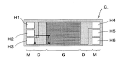
- a fuel cell (single cell) C shown in FIG. 1 includes a membrane electrode structure 2 having a frame 1 around it, and two separators 3 and 3 sandwiching the frame 1 and the membrane electrode structure 2.
- the frame 1 has a thin plate shape with a substantially constant thickness, and most of the frame 1 except the edge is thinner than the thickness of the membrane electrode structure 2. And it has the distribution area (diffuser part mentioned below) which distributes the gas for reaction between frame 1 and both separators 3 and 3. It is preferable that the frame 1 is a resin and the separator 3 is a metal because it is easy to manufacture.
- the membrane electrode structure 2 is generally called MEA (Membrane Electrode Assembly), and has a structure in which, for example, an electrolyte layer made of a solid polymer is sandwiched between an air electrode layer (cathode) and a fuel electrode layer (anode). Have.
- an oxidant gas (air) that is the other reaction gas is supplied to the air electrode layer, and a fuel gas (hydrogen) that is one reaction gas is supplied to the fuel electrode layer.
- Power is generated by an electrochemical reaction.
- the membrane electrode structure 2 includes those having a gas diffusion layer made of carbon paper or a porous body on the surfaces of the air electrode layer and the fuel electrode layer.
- the frame 1 is integrated with the membrane electrode structure 2 by resin molding (for example, injection molding).
- the frame 1 has a rectangular shape with the membrane electrode structure 2 in the center.
- the frame 1 has three manifold holes H1 to H6 arranged at both ends, and a region from each manifold hole group to the membrane electrode structure 2 is a reaction gas flow region.
- Each of the frame 1 and the separators 3 and 3 has a rectangular shape having substantially the same vertical and horizontal dimensions.
- Each separator 3 is formed by press-molding a metal plate such as stainless steel.
- Each separator 3 has a central portion corresponding to the membrane electrode structure 2 formed in a wave shape in a cross section in the short side direction. This wave shape is continuous in the long side direction as shown in the figure.
- each separator 3 has a convex portion in contact with the membrane electrode structure 2 at the central portion corresponding to the membrane electrode structure 2 in the wave shape, and the concave portions in the wave shape are flow paths for the reaction gas. It becomes.
- Each separator 3 has manifold holes H1 to H6 that are equivalent to the manifold holes H1 to H6 of the frame 1 at both ends, and the region from each manifold hole group to the corrugated section has a reaction gas flow. It becomes an area.
- the fuel cell C includes a power generation unit G that is a region of the membrane electrode structure 2 at the center. Further, on both sides of the power generation unit G, manifold units M and M that supply and discharge the reaction gas, and diffuser units D and D that are reaction gas flow regions from each manifold unit M to the power generation unit G are provided. It has become.
- the diffuser portion D which is a flow region for the reaction gas, is formed not only on both ends of the cell in FIG. 2, but also between the frame 1 and the separators 3 and 3 on both sides, that is, on the anode and cathode sides. ing.
- each of the manifold holes H1 to H3 is for supplying an oxidant gas (H1), for supplying a cooling fluid (H2), and for supplying a fuel gas (H3).
- H1 oxidant gas
- H2 cooling fluid
- H3 fuel gas
- the manifold holes H4 to H6 are for fuel gas discharge (H4), cooling fluid discharge (H5), and oxidant gas discharge (H6).
- Each flow path is formed in communication with each other in the stacking direction. The supply and discharge may be partially or entirely reversed in positional relationship.
- the fuel cell C is provided with a gas seal SL between the edges of the frame 1 and each separator 3 and around the manifold holes H1 to H6.
- a gas seal SL is also provided between cells, that is, between adjacent separators 3.
- a cooling fluid is circulated between the adjacent separators 3 and 3.
- the above gas seal SL hermetically separates the flow regions of the oxidant gas, the fuel gas, and the cooling fluid between the individual layers, and manifold holes H1 to H6 so that a predetermined fluid flows between the layers.
- An opening is provided at an appropriate location on the peripheral edge of the.
- a plurality of fuel cells C having the above-described configuration are stacked to form a fuel cell stack FS as shown in FIG.
- the fuel cell stack FS has a current collector plate 4A and a spacer at one end (right end in FIG. 3) in the cell stacking direction with respect to the stack A of the fuel cells C. 5 is provided with an end plate 6A, and the other end is provided with an end plate 6B via a current collecting plate 4B. Further, the fuel cell stack FS is provided with fastening plates 7A and 7B on both surfaces (upper and lower surfaces in FIG. 3) on the long side of the fuel cell C with respect to the laminate A, and the short side and Reinforcing plates 8A and 8B are provided on both sides.
- the fastening plates 7A and 7B and the reinforcing plates 8A and 8B are connected to both end plates 6A and 6B by bolts B.
- the fuel cell stack FS has a case-integrated structure as shown in FIG. 3B.
- the fuel cell stack FS is constrained and pressurized in the cell stacking direction to contact each fuel cell C with a predetermined contact surface. Apply pressure to maintain good gas sealing and conductivity.
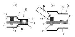
- the fuel battery cell C is disposed on at least one of the opposing surfaces of the frame 1 and the separator 3 on the other side. While providing the protrusion 10 which contact
- the frame 1 in the diffuser portion D on the cathode side (upper side in the figure), the frame 1 is provided with a protrusion 10 that contacts the separator 3, and the separator 3 and the tip of the protrusion 10 are bonded (reference numeral).
- the frame 1 and the separator 3 are arranged apart from each other.
- the positions of the cathode and anode may be upside down.
- the protrusions 10 of this embodiment have a truncated cone shape, are integrally formed with the resin frame 1, and are arranged at predetermined intervals as shown in FIG.
- the protrusion 10 is not particularly limited in shape or the like, and may be any as long as it does not hinder the flow of the reaction gas.
- a protrusion 11 having a shape similar to that of the protrusion 10 is provided on the anode-side surface (the lower surface in FIG. 4) of the frame 1.
- the protrusion 11 is lower than the protrusion 10 on the cathode side and forms a gap between the separator 3 and abuts against the separator 3 when the frame 1 and the separator 3 are displaced in the approaching direction. To prevent excessive displacement.
- the frame 1 and the separator 3 are separated from each other in the anode-side diffuser portion D. Therefore, when the fuel cell stack FS is configured, the pressure in the stacking direction is mainly a membrane. It acts between the electrode structure 2 and the separator 3, and a sufficient contact surface pressure between the membrane electrode structure 2 and the separator 3 can be secured.
- the fuel cell C can absorb the displacement in the thickness direction by the gap between the frame 1 and the separator 3 in the diffuser portion D on the anode side. That is, the fuel cell C can absorb the dimensional tolerances and manufacturing variations of the components and the aging displacement in the thickness direction of the membrane electrode structure 2 through the gap. Thereby, when the fuel cell C constitutes the fuel cell stack FS, the fuel cell C can suppress variations in performance such as contact surface pressure and gas flow rate in individual cells.
- the durability of the membrane electrode structure 2 having the frame 1 is improved by bonding the tip of the protrusion 10 of the frame 1 and the separator 3 in the diffuser portion D on the cathode side. That is, in the fuel cell C, even if a gas differential pressure is generated between the cathode side and the anode side, the frame 1 is held by the separator 3 by the protrusion 10 bonded to the separator 3. Even when any pressure on the anode side becomes high, the displacement of the frame 1 can be suppressed. As a result, the fuel cell C can prevent the bending stress from concentrating on the joint between the frame 1 and the membrane electrode structure 2.
- the fuel cell C can absorb the displacement in the thickness direction by the gap provided between the frame 1 and the separator 3, and at the same time hold the frame 1 by the protrusion 10 bonded to the separator 3. Therefore, both the optimization of the performance of each cell when the fuel cell stack FS is configured and the improvement of the durability of the joint portion between the frame 1 and the membrane electrode structure 2 can be achieved.
- FIG. 5 is a diagram for explaining another embodiment of the fuel battery cell of the present invention.
- the same components as those of the previous embodiment shown in FIGS. 1 to 4 are denoted by the same reference numerals, and detailed description thereof is omitted.
- the upper side in the figure is described as the cathode side, but the positions of the cathode and the anode may be upside down.
- the separator 3 is provided with a protrusion 12 in contact with the frame 1 on the other side, and the frame 1 and the tip of the protrusion 12 are bonded ( Q) Yes.
- the protrusions 12 are arranged at predetermined intervals so as not to disturb the flow of the reaction gas, like the protrusions of the previous embodiment.
- the frame 1 and the separator 3 are spaced apart.
- the displacement in the thickness direction can be absorbed by the gap provided between the frame 1 and the separator 3 as in the previous embodiment, and at the same time, the fuel cell C is provided in the separator 3. Since the frame 1 is held by the protrusions 12, both the optimization of the performance of each cell when the fuel cell stack FS is configured and the improvement of the durability of the joint between the frame 1 and the membrane electrode structure 2 are achieved. be able to.
- FIG. 6 is a diagram for explaining still another embodiment of the fuel battery cell of the present invention.
- a fuel battery cell C shown in FIG. 6A has a cathode-side diffuser portion D provided with a protrusion 13 in contact with the mating side on at least one of the opposing surfaces of the frame 1 and the separator 3.
- the protrusion 13 is formed of an adhesive interposed between the frame 1 and the separator 3. Even in the protrusions 13, they are arranged at predetermined intervals so as not to disturb the flow of the reaction gas.
- the frame 1 and the separator 3 are spaced apart.
- the adhesive forming the protrusion 13 can be selected from materials specialized in adhesive strength, and for example, an epoxy-based material can be used.
- the protrusion (adhesive material) 13 can be formed in a predetermined shape in advance, but more desirably, it is discharged from a nozzle N of an adhesive supply device (not shown) as shown in FIG. Apply to frame 1. And since the protrusion (adhesive material) 13 is bonded to both by joining the frame 1 and the separator 3, it is equivalent to bonding the separator 3 on the other side and the tip. Note that, contrary to the illustrated example, it is naturally possible to provide (apply) the protrusion 13 on the separator 3.
- the protrusions 13 are formed of an adhesive, so that the protrusions of the frame 1 and the separator 3 are eliminated.
- the shape can be simplified, and the protrusion 13 can be formed together with the step of providing the gas seal SL (see FIG. 1), which contributes to an improvement in production efficiency and a reduction in manufacturing cost. Can do.
- an adhesive such as silicone rubber, fluororubber, and polyolefin rubber.
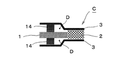
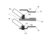
- FIG. 7 is a view for explaining still another embodiment of the fuel battery cell of the present invention.
- a fuel cell C shown in FIG. 7A has a protrusion in contact with the mating side at least one of the opposing surfaces of the frame 1 and the separator 3 in the diffuser portion D on either the cathode side or the anode side. While providing the part 10, the diffuser part D of the other side is interposed between the flame
- the elastic bodies 14 are arranged at predetermined intervals so as not to disturb the flow of the reaction gas, like the protrusions of the previous embodiment.
- the fuel cell C is provided with a protrusion 10 in contact with the separator 3 on the frame 1 in the cathode-side diffuser portion D, and between the frame 1 and the separator 3 in the anode-side diffuser portion D. , An elastic body 14 in contact with both is interposed.
- the elastic body 14 can be provided on the separator 3 as shown in FIG. 7B or on the frame 1 as shown in FIG. 7C.
- the elastic body 14 can be formed in a predetermined shape in advance, but more preferably, it is formed of an adhesive that is applied in a molten state and has elasticity after being cured.
- the adhesive forming the elastic body 14 for example, a material such as silicone rubber, fluorine rubber, or polyolefin rubber can be used. Even in this elastic body (adhesive material) 14, it is applied to the frame 1 or the separator 3 in the same manner as the protrusion (reference numeral 13 in FIG. 6) formed by the previous adhesive material, and after curing, the frame 1 and the separator 3 are applied. Will be in contact with the other party.
- the fuel cell C described above absorbs displacement in the thickness direction through the gap between the anode-side separator 3 and the frame 1, whereas the anode-side elastic body 14. To absorb the displacement in the thickness direction.
- the fuel battery cell C holds the frame 1 by the protrusion 10 and the elastic body 14 of the frame 1.
- the elastic body 14 can be formed together with the step of providing the gas seal SL (see FIG. 1).
- the elastic body 14 and the gas seal SL can be formed of the same material, which can contribute to improvement in production efficiency and reduction in manufacturing cost.
- an adhesive such as silicone rubber, fluororubber, and polyolefin rubber.
- the adhesive has a low adhesive strength. But you can. Therefore, the surface treatment of the adhesive surface can be simplified or eliminated, and an inexpensive adhesive can be employed, thereby further reducing the manufacturing cost.
- FIG. 8 is a diagram for explaining still another embodiment of the fuel battery cell of the present invention.
- an elastic body 14 in contact with both is interposed between the frame 1 and the separator 3 in both of the diffuser portions D on the cathode side and the anode side. That is, in the diffuser portion D on the cathode side and the anode side, at least one of the opposing surfaces of the frame 1 and the separator 3 is provided with a protrusion that contacts the mating side.
- an elastic body 14 interposed between the separator 3 and the separator 3. Similar to the previous embodiment, the elastic bodies 14 are arranged at predetermined intervals so as not to disturb the flow of the reaction gas. Even in the elastic body 14, it is possible to form it into a predetermined shape in advance, but more desirably, it is formed of an adhesive material that is applied in a molten state and has elasticity after being cured.
- the fuel cell C described above absorbs displacement in the thickness direction by both elastic bodies 14 on the cathode side and the anode side, and holds the frame 1 by both elastic bodies 14.
- both the optimization of the performance of each cell when the fuel cell stack FS is configured and the improvement of the durability of the joint between the frame 1 and the membrane electrode structure 2 are achieved. Can do.
- both diffuser portions D are provided with elastic bodies 14, and a recess 15 (or 16) is formed on at least one of the opposing surfaces of the frame 1 and the separator 3.
- the elastic body 14 is disposed in the recess 15 (or 16).
- the elastic bodies 14 are arranged at predetermined intervals so as not to disturb the flow of the reaction gas, they are similarly formed at predetermined intervals even in the recesses 15 (or 16).
- a recess 15 is formed in the separator 3, and an elastic body 14 is disposed in the recess 15.
- the recessed part 15 can apply the back side part of the convex part 17 press-molded by the separator 3.
- FIG. 10 the fuel cell C shown in FIG. 10 has a recess 16 formed in the frame 1, and an elastic body 14 is disposed in the recess 16.
- the recess 16 can be formed by surface grinding such as sandblasting.
- Each of the fuel cells C described above performs displacement absorption in the thickness direction by both elastic bodies 14 and holds the frame 1 by both elastic bodies 14 to form a fuel cell stack FS, as in the previous embodiment.
- the optimization of the performance of each cell and the improvement of the durability of the joint between the frame 1 and the membrane electrode structure 2 can be achieved at the same time.
- the recesses 15 and 16 facilitate the positioning of the elastic body 14, which can contribute to the improvement of manufacturing efficiency and increase the contact area between the elastic body 14 and the frame 1 or the separator 3. Adhesive strength and stability will increase. Furthermore, in addition to improving the durability with stabilization of the elastic body 14, the expansion / contraction length of the elastic body 14 is increased by the depth of the recesses 15, 16, so the displacement absorption range in the thickness direction of the fuel cell C Can be increased.
- the convex portion 17 becomes a flow path forming portion of the cooling fluid. That is, since the fuel cell C has a structure in which the cooling fluid is circulated between the adjacent ones in the stacked state as described above, the portion for forming the flow path between the adjacent separators 3 is formed. And parts are required. Therefore, as in this embodiment, if the back side portion of the convex portion 17 press-molded in the separator 3 is a concave portion 15, the convex portion 17 for forming the flow path and the concave portion 15 for arranging the elastic body 14 are provided. It can be formed in one process and is very effective in terms of manufacturing efficiency and manufacturing cost.
- the concave portion 16 of the frame 1 is formed by surface grinding, and particularly if the surface texture is formed into fine irregularities by sandblasting, the adhesion area of the elastic body 14 is increased.
- the adhesive strength can be further increased, whereby the elastic body 14 can be prevented from peeling and the durability can be further increased.
- the elastic body 14 shown in FIGS. 7 to 10 can be formed in the same process as the gas seal SL (see FIG. 1) as shown in FIG.
- the elastic body 14 can be formed by injection molding, baking, or the like, but if an adhesive material that exhibits elasticity after curing is used as a material, the gas seal SL and the protrusion 13 shown in FIG. They can be formed with the same configuration (material) and are very effective in terms of manufacturing efficiency and manufacturing cost.
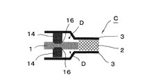
- FIG. 12 is a diagram for explaining still another embodiment of the fuel battery cell of the present invention.
- the illustrated fuel cell C has a recess 16 in the frame 1 at the diffuser portion D on the cathode side (upper side in the figure) and a recess 15 in the separator 3 at the diffuser portion D on the anode side (lower side in the figure).
- the concave portion 15 may be provided in the separator 3 in the cathode side diffuser portion D
- the concave portion 16 may be provided in the frame 1 in the anode side diffuser portion D.
- the recesses 15 and 16 may be provided on the surfaces facing the same direction, and preferably on the upper surface during assembly manufacturing.
- an adhesive material having elasticity after curing is used, and a molten adhesive material is discharged from a nozzle N of an adhesive material supply device (not shown) and applied to the recesses 15 and 16 and cured.
- the elastic body 14 is formed. Therefore, as shown in the illustrated example, if the recesses 15 and 16 are provided on the upper surface of the frame 1 and the separator 3 in both diffuser portions D, the molten adhesive can be applied from the same direction. In addition to being able to prevent the adhesive from flowing out, it is effective in terms of manufacturing efficiency, and the elastic system 14 can be formed well.
- the fuel cell C of the present invention has the optimized performance of each cell when the fuel cell stack FS is configured, and the joint between the frame 1 and the membrane electrode structure 2. It is possible to achieve both improved durability. Therefore, in the fuel cell stack FS formed by laminating a plurality of the above-described fuel cells C, the power generation performance and durability performance of each fuel cell C can be made uniform, and stable power generation can be performed over a long period of time. it can.
- the configuration of the fuel cell of the present invention is not limited to the above-described embodiments, and details of the configuration can be appropriately changed without departing from the gist of the present invention.
- an example in which the positions of the protrusions and the elastic body and the positions of the elastic body and the elastic body coincide with each other is illustrated. It may be shifted. It is also possible to combine the configurations of the above embodiments.
Landscapes
- Life Sciences & Earth Sciences (AREA)
- Engineering & Computer Science (AREA)
- Manufacturing & Machinery (AREA)
- Sustainable Development (AREA)
- Sustainable Energy (AREA)
- Chemical & Material Sciences (AREA)
- Chemical Kinetics & Catalysis (AREA)
- Electrochemistry (AREA)
- General Chemical & Material Sciences (AREA)
- Fuel Cell (AREA)
Abstract
従来の燃料電池セルでは、積層して燃料電池スタックを構成した際に、全てのセルの性能を適正化することが困難であると共に、カソード側とアノード側との差圧により樹脂フレームと膜電極構造体との接合部の耐久性が低下するおそれがあった。 フレーム1を有する膜電極構造体2と、これらを挟持するセパレータ3を備え、フレーム1と各セパレータ3との間にディフューザ部Dを有する燃料電池セルCであって、カソード側及びアノード側のいずれか一方側のディフューザ部Dにおいて、フレーム1及びセパレータ3の一方の面に、相手側に接する突部10を設けると共に、相手側と突部10の先端とを接着し、他方側のディフューザ部Dにおいて、フレーム1とセパレータ3とを離間して配置したことにより、燃料電池スタックFSを構成した際の各セルCの性能の適正化と、フレーム1と膜電極構造体2との接合部の耐久性の向上を両立させた。
Description
本発明は、燃料電池の発電要素として用いられる燃料電池セル(単セル)に関し、とくに、複数枚積層して燃料電池スタックを構成する燃料電池セルに関するものである。
この種の燃料電池セルとしては、例えば、特許文献1に記載されているものがある。特許文献1に記載の燃料電池セルは、電解質膜を燃料極と空気極とで挟持した膜電極構造体(MEA:Membrane Electrode Assembly)と、膜電極構造体の周囲を保持する樹脂フレームと、膜電極構造体及び樹脂フレームを挟む二枚のセパレータを備えている。
上記燃料電池セルは、樹脂フレームと両セパレータとの間に、反応用ガスのマニホールド部及び整流部を夫々有すると共に、樹脂フレームの両面に、各セパレータに接触する突起が一体成形してあり、その突起により整流部の流路高さを維持している。そして、上記燃料電池セルは、複数枚を積層すると共に、その積層方向に一定の荷重を付与した状態にして燃料電池スタックを構成する。
ところで、この種の燃料電池セルは、各構成部品に寸法公差や製造上のばらつきがあり、膜電極構造体の厚さの経年変位などにも僅かな差がある。このため、従来の燃料電池セル、すなわち樹脂フレームの突起とセパレータとを接触させて樹脂フレームを拘束した構造を有する燃料電池セルでは、これを複数枚積層して燃料電池スタックを構成した際に、膜電極構造体に対する接触面圧やガス流量などの性能にもばらつきが生じ、全てのセルの性能を適正化することが困難になっている。
さらに、上記したような燃料電池セルでは、燃料電池の運転状況に応じてカソード側とアノード側とでガスの差圧が発生し、その差圧により樹脂フレームと膜電極構造体との接合部に曲げ応力が集中して、接合部の耐久性が低下するおそれがあった。
本発明は、上記従来の状況に鑑みて成されたもので、周囲にフレームを有する膜電極構造体と、フレーム及び膜電極構造体を挟持する二枚のセパレータを備えた燃料電池セルにおいて、燃料電池スタックを構成した際の各セルの性能の適正化と、フレームと膜電極構造体との接合部の耐久性の向上を両立させることができる燃料電池セルを提供することを目的としている。
本発明の燃料電池セルは、周囲にフレームを有する膜電極構造体と、フレーム及び膜電極構造体を挟持する二枚のセパレータを備え、フレームと各セパレータとの間に反応用ガスを流通させる夫々のディフューザ部を有している。
そして、燃料電池セルは、カソード側及びアノード側のいずれか一方側のディフューザ部において、フレーム及びセパレータの相対向面の少なくとも一方の面に、相手側に接する突部を設けると共に、相手側と突部の先端とを接着し、他方側のディフューザ部において、フレームとセパレータとを離間して配置した構成としており、上記構成をもって従来の課題を解決するための手段としている。
また、本発明の燃料電池セルは、フレームと各セパレータの縁部同士の間にガスシールを設け、一方側のディフューザ部において、フレーム及びセパレータの相対向面の少なくとも一方の面に、相手側に接する突部を設けると共に、他方側のディフューザ部において、フレームとセパレータの間に、双方に接する弾性体を介装し、弾性体とガスシールとが同一材料で形成してあることを特徴としている。
本発明の燃料電池セルによれば、フレームとセパレータとの間に設けた隙間あるいは弾性体により厚さ方向の変位吸収が可能であると同時に、フレーム及びセパレータのいずれかに設けた突部あるいは弾性体によりフレームを保持することから、燃料電池スタックを構成した際の各セルの性能の適正化と、フレームと膜電極構造体との接合部の耐久性の向上を両立させることができる。
図1及び図2は、本発明の燃料電池セルの一実施形態を説明する図である。
図1に示す燃料電池セル(単セル)Cは、周囲にフレーム1を有する膜電極構造体2と、フレーム1及び膜電極構造体2を挟持する二枚のセパレータ3,3を備えている。フレーム1は、ほぼ一定の厚さの薄板状を成しており、その縁部を除く大部分が膜電極構造体2の厚さよりも薄いものである。そして、フレーム1と両セパレータ3,3との間に反応用ガスを流通させる流通領域(後記するディフューザ部)を有している。なお、フレーム1は樹脂であり、セパレータ3は金属であることが、製造しやすいために望ましい。
図1に示す燃料電池セル(単セル)Cは、周囲にフレーム1を有する膜電極構造体2と、フレーム1及び膜電極構造体2を挟持する二枚のセパレータ3,3を備えている。フレーム1は、ほぼ一定の厚さの薄板状を成しており、その縁部を除く大部分が膜電極構造体2の厚さよりも薄いものである。そして、フレーム1と両セパレータ3,3との間に反応用ガスを流通させる流通領域(後記するディフューザ部)を有している。なお、フレーム1は樹脂であり、セパレータ3は金属であることが、製造しやすいために望ましい。
膜電極構造体2は、一般に、MEA(Membrane Electrode Assembly)と呼ばれるものであって、例えば固体高分子から成る電解質層を空気極層(カソード)と燃料極層(アノード)とで挟持した構造を有している。この膜電極構造体2は、空気極層に他方の反応用ガスである酸化剤ガス(空気)が供給されると共に、燃料極層に一方の反応用ガスである燃料ガス(水素)が供給されて、電気化学反応により発電をする。なお、膜電極構造体2としては、空気極層と燃料極層の表面に、カーボンペーパや多孔質体等から成るガス拡散層を備えたものも含まれる。
フレーム1は、樹脂成形(例えば射出成形)により膜電極構造体2と一体化してあり、この実施形態では、膜電極構造体2を中央にして長方形状を成している。また、フレーム1は、両端部に、各々三個ずつのマニホールド穴H1~H6が配列してあり、各マニホールド穴群から膜電極構造体2に至る領域が反応用ガスの流通領域となる。このフレーム1及び両セパレータ3,3は、いずれもほぼ同等の縦横寸法を有する長方形状である。
各セパレータ3は、夫々ステンレス等の金属板をプレス成形したものである。各セパレータ3は、膜電極構造体2に対応する中央部分が、短辺方向の断面において波形状に形成してある。この波形状は図示の如く長辺方向に連続している。これにより、各セパレータ3は、波形状における膜電極構造体2に対応する中央部分では、各凸部分が膜電極構造体2に接触すると共に、波形状における各凹部分が反応用ガスの流路となる。
また、各セパレータ3は、両端部に、フレーム1の各マニホールド穴H1~H6同等のマニホールド穴H1~H6を有し、各マニホールド穴群から断面波形状の部分に至る領域が反応用ガスの流通領域となる。
上記のフレーム1及び膜電極構造体2と両セパレータ3,3は、重ね合わせて燃料電池セルCを構成する。このとき、燃料電池セルCは、とくに図2に示すように、中央に、膜電極構造体2の領域である発電部Gを備えている。そして、発電部Gの両側に、反応用ガスの供給及び排出を行うマニホールド部M,Mと、各マニホールド部Mから発電部Gに至る反応用ガスの流通領域であるディフューザ部D,Dを備えたものとなっている。
ここで、反応用ガスの流通領域であるディフューザ部Dは、図2中のセル両端側だけでなく、フレーム1と両側のセパレータ3,3との間、つまりアノード側及びカソード側に夫々形成されている。
図2の左側に示す一方のマニホールド部Mにおいて、各マニホールド穴H1~H3は、酸化剤ガス供給用(H1)、冷却流体供給用(H2)及び燃料ガス供給用(H3)であり、積層方向に互いに連通して夫々の流路を形成する。また、図2の右側に示す他方のマニホールド部Mにおいて、各マニホールド穴H4~H6は、燃料ガス排出用(H4)、冷却流体排出用(H5)及び酸化剤ガス排出用(H6)であり、積層方向に互いに連通して夫々の流路を形成する。なお、供給用と排出用は、一部または全部が逆の位置関係でも良い。
さらに、燃料電池セルCは、図1に示すように、フレーム1と各セパレータ3の縁部同士の間や、マニホールド穴H1~H6の周囲に、ガスシールSLが設けてある。また、燃料電池セルCを複数枚を積層した状態では、セル同士すなわち隣接するセパレータ3同士の間にもガスシールSLを設ける。この実施形態では、隣接するセパレータ3,3間に冷却流体を流通させる構造である。
上記のガスシールSLは、個々の層間において、酸化剤ガス、燃料ガス及び冷却流体の夫々の流通域を気密的に分離すると共に、その層間に所定の流体が流れるように、マニホールド穴H1~H6の周縁部の適当な箇所に開口を設ける。
上記構成を備えた燃料電池セルCは、複数枚を積層して、図3に示すような燃料電池スタックFSを構成する。
燃料電池スタックFSは、図3(A)に示すように、燃料電池セルCの積層体Aに対し、セル積層方向の一端部(図3中で右側端部)に、集電板4A及びスペーサ5を介してエンドプレート6Aが設けてあると共に、他端部に、集電板4Bを介してエンドプレート6Bが設けてある。また、燃料電池スタックFSは、積層体Aに対し、燃料電池セルCの長辺側となる両面(図3中で上下面)に、締結板7A,7Bが設けてあると共に、短辺側となる両面に、補強板8A,8Bが設けてある。
そして、燃料電池スタックFSは、各締結板7A,7B及び補強板8A,8BをボルトBにより両エンドプレート6A,6Bに連結する。このようにして、燃料電池スタックFSは、図3(B)に示すようなケース一体型構造となり、積層体Aをセル積層方向に拘束・加圧して個々の燃料電池セルCに所定の接触面圧を加え、ガスシール性や導電性等を良好に維持する。
ここで、上記したような燃料電池セルCでは、各構成部品に寸法公差や製造上のばらつきがあると共に、膜電極構造体2の厚さの経年変位などにも僅かな差がある。また、燃料電池の運転状況に応じてカソード側とアノード側とでガスの差圧が発生し、その差圧によりフレーム1と膜電極構造体2との接合部に曲げ応力が集中しやすい。
そこで、燃料電池セルCは、図4に示すように、カソード側及びアノード側のいずれか一方側のディフューザ部Dにおいて、フレーム1及びセパレータ3の相対向面の少なくとも一方の面に、相手側と接する突部10を設けると共に、相手側と突部10の先端とを接着している。そして、他方側のディフューザ部Dにおいて、フレーム1とセパレータ3とを離間して配置したものとなっている。
図示例の燃料電池セルCでは、カソード側(図中上側)のディフューザ部Dにおいて、フレーム1に、セパレータ3に接する突部10を設けると共に、セパレータ3と突部10の先端とを接着(符号Q)し、アノード側(図中下側)のディフューザ部Dにおいて、フレーム1とセパレータ3とを離間して配置している。なお、カソード及びアノードの位置は上下逆でも構わない。
セパレータ3と突部10との接着には、双方の材料(金属と樹脂)を考慮したうえで、これらの接着に有効な周知の接着剤を用いることができ、このほか、超音波溶着などの適宜の接着手段を採用することもできる。
この実施形態の突部10は、円錐台形状であって、樹脂製のフレーム1に一体成形してあり、図1に示すように所定間隔で配置してある。この突部10は、形状等がとくに限定されるものではなく、反応用ガスの流通を妨げないものであれば良い。
また、この実施形態では、フレーム1のアノード側の面(図4で下側の面)に、突部10と類似形状の突部11が設けてある。この突部11は、カソード側の突部10よりも低くて、セパレータ3との間に隙間を形成しており、フレーム1とセパレータ3が接近する方向に変位した際に、セパレータ3に当接して過大な変位を阻止する。
上記構成を備えた燃料電池セルCは、アノード側のディフューザ部Dにおいてフレーム1とセパレータ3とが離間しているので、燃料電池スタックFSを構成した際に、積層方向の加圧力が主に膜電極構造体2とセパレータ3との間に作用し、膜電極構造体2とセパレータ3との接触面圧を充分に確保することができる。
また、燃料電池セルCは、アノード側のディフューザ部Dにおけるフレーム1とセパレータ3との隙間により、厚さ方向の変位吸収が可能である。すなわち、燃料電池セルCは、各構成部品の寸法公差や製造上のばらつき、膜電極構造体2の厚さ方向の経年変位があっても、上記隙間によりそれらを吸収することができる。これにより、燃料電池セルCは、燃料電池スタックFSを構成した際に、個々のセルにおける接触面圧やガス流量等の性能のばらつきを抑制し得るものとなる。
さらに、燃料電池セルCは、カソード側のディフューザ部Dにおいて、フレーム1の突部10の先端とセパレータ3とを接着したことにより、フレーム1を有する膜電極構造体2の耐久性が向上する。すなわち、燃料電池セルCは、カソード側とアノード側とでガスの差圧が生じても、セパレータ3に接着した上記突部10によりフレーム1が同セパレータ3に保持されているので、カソード側及びアノード側のいずれの圧力が高くなった場合でも、フレーム1の変位を抑制することができる。これにより、燃料電池セルCは、フレーム1と膜電極構造体2との接合部に曲げ応力が集中するのを阻止し得るものとなる。
このようにして、燃料電池セルCは、フレーム1とセパレータ3との間に設けた隙間により厚さ方向の変位吸収が可能であると同時に、セパレータ3に接着した突部10によりフレーム1を保持することから、燃料電池スタックFSを構成した際の各セルの性能の適正化と、フレーム1と膜電極構造体2との接合部の耐久性の向上を両立させることができる。
図5は、本発明の燃料電池セルの他の実施形態を説明する図である。なお、以下の実施形態において、図1~図4に示す先の実施形態と同一の構成部位は、同一符号を付して詳細な説明を省略する。また、以下の実施形態では、図中上側をカソード側として説明するが、カソード及びアノードの位置は上下逆でもよい。
図示の燃料電池セルCは、カソード側(上側)のディフューザ部Dにおいて、セパレータ3に、相手側であるフレーム1に接する突部12を設けると共に、フレーム1と突部12の先端とを接着(Q)している。突部12は、先の実施形態の突部と同様に、反応用ガスの流通を妨げないように所定間隔で配置してある。そして、アノード側のディフューザ部Dにおいて、フレーム1とセパレータ3とを離間して配置している。
上記の燃料電池セルCにあっても、先の実施形態と同様に、フレーム1とセパレータ3との間に設けた隙間により厚さ方向の変位吸収が可能であると同時に、セパレータ3に設けた突部12によりフレーム1を保持することから、燃料電池スタックFSを構成した際の各セルの性能の適正化と、フレーム1と膜電極構造体2との接合部の耐久性の向上を両立させることができる。
図6は、本発明の燃料電池セルのさらに他の実施形態を説明する図である。図6(A)に示す燃料電池セルCは、カソード側のディフューザ部Dにおいて、フレーム1及びセパレータ3の相対向面の少なくとも一方の面に、相手側に接する突部13を設けたものであるが、その突部13が、フレーム1とセパレータ3との間に介装した接着材で形成してある。この突部13にあっても、反応用ガスの流通を妨げないように所定間隔で配置してある。また、アノード側のディフューザ部Dにおいては、フレーム1とセパレータ3とを離間して配置している。
突部13を形成する接着材は、接着力に特化した材料から選択することができ、例えばエポキシ系の材料を使用することができる。突部(接着材)13は、予め所定形状に成形しておくことも可能であるが、より望ましくは、図6(B)に示すように、図示しない接着材供給装置のノズルNから吐出させてフレーム1に塗布する。そして、突部(接着材)13は、フレーム1とセパレータ3を接合することで双方に接着されるので、相手側であるセパレータ3と先端とを接着するのと同等である。なお、図示例とは逆に、セパレータ3に突部13を設ける(塗布する)ことも当然可能である。
上記の燃料電池セルCにあっても、先の実施形態と同様の効果を得ることができるうえに、突部13を接着材で形成したことから、フレーム1やセパレータ3の突部を廃止して形状を簡素化することができ、また、ガスシールSL(図1参照)を設ける工程とともに突部13を形成することが可能なので、生産効率の向上や製造コストの低減などにも貢献することができる。なお、ガスシールSLと突部13とを同工程で形成する場合には、両方の用途に適した材料、例えばシリコーンゴム、フッ素ゴム、及びポリオレフィンゴムなどの接着剤を用いることが望ましい。
図7は、本発明の燃料電池セルのさらに他の実施形態を説明する図である。図7(A)に示す燃料電池セルCは、カソード側及びアノード側のいずれか一方側のディフューザ部Dにおいて、フレーム1及びセパレータ3の相対向面の少なくとも一方の面に、相手側に接する突部10を設けると共に、他方側のディフューザ部Dにおいて、フレーム1とセパレータ3の間に、双方に接する弾性体14を介装している。この弾性体14は、先の実施形態の突部と同様に、反応用ガスの流通を妨げないように所定間隔で配置してある。
具体的には、燃料電池セルCは、カソード側のディフューザ部Dにおいて、フレーム1に、セパレータ3に接する突部10を設けると共に、アノード側のディフューザ部Dにおいて、フレーム1とセパレータ3の間に、双方に接する弾性体14を介装している。弾性体14は、図7(B)に示す如くセパレータ3に設けたり、図7(C)に示す如くフレーム1に設けることができる。
また、弾性体14は、予め所定形状に成形しておくことも可能であるが、より望ましくは、溶融状態で塗布されて硬化後に弾力性を有する接着材で形成する。弾性体14を形成する接着材は、例えばシリコーンゴム、フッ素ゴム、あるいはポリオレフィンゴムなどの材料を使用することができる。この弾性体(接着材)14にあっても、先の接着材で形成した突部(図6の符号13)と同様に、フレーム1又はセパレータ3に塗布され、硬化後、フレーム1とセパレータ3を接合することで相手側に接することとなる。
上記の燃料電池セルCは、図4~図6に示す実施形態では、アノード側のセパレータ3とフレーム1との隙間により厚さ方向の変位吸収を行うのに対して、アノード側の弾性体14により厚さ方向の変位吸収を行う。そして、燃料電池セルCは、フレーム1の突部10及び弾性体14によりフレーム1を保持する。これにより、先の実施形態と同様に、燃料電池スタックFSを構成した際の各セルの性能の適正化と、フレーム1と膜電極構造体2との接合部の耐久性の向上を両立させることができる。
また、上記の燃料電池セルCは、硬化後に弾力性を有する接着材で弾性体14を形成したことから、ガスシールSL(図1参照)を設ける工程とともに弾性体14を形成することが可能であり、すなわち弾性体14とガスシールSLを同一材料で形成することができ、生産効率の向上や製造コストの低減などにも貢献することができる。弾性体14とガスシールSLとを同工程で形成する場合には、両方の用途に適した材料、例えばシリコーンゴム、フッ素ゴム、及びポリオレフィンゴムなどの接着剤を用いることが望ましい。さらに、上記の燃料電池セルCは、突部10や弾性体14を相手側に接触させるだけで、変位吸収機能やフレーム1の保持機能を得ることができるので、接着材は接着強度の低いものでもよい。そのため、接着面の表面処理を簡素にし又は廃止し得ると共に、安価な接着材を採用することができ、製造コストのさらなる低減を図ることができる。
図8は、本発明の燃料電池セルのさらに他の実施形態を説明する図である。図示の燃料電池セルCは、カソード側及びアノード側の両方のディフューザ部Dにおいて、フレーム1とセパレータ3の間に、双方に接する弾性体14を介装している。すなわち、カソード側及びアノード側のディフューザ部Dにおいて、フレーム1及びセパレータ3の相対向面の少なくとも一方の面に、相手側に接する突部を設けたものであるが、その突部が、フレーム1とセパレータ3との間に介装した弾性体14で形成してある。弾性体14は、先の実施形態と同様に、反応用ガスの流通を妨げないように所定間隔で配置してある。この弾性体14にあっても、予め所定形状に成形しておくことも可能であるが、より望ましくは、溶融状態で塗布されて硬化後に弾力性を有する接着材で形成する。
上記の燃料電池セルCは、カソード側及びアノード側の両弾性体14により厚さ方向の変位吸収を行うと共に、両弾性体14によりフレーム1を保持する。これにより、先の実施形態と同様に、燃料電池スタックFSを構成した際の各セルの性能の適正化と、フレーム1と膜電極構造体2との接合部の耐久性の向上を両立させることができる。
図9及び10は、本発明の燃料電池セルのさらに他の実施形態を説明する図である。図示の燃料電池セルCは、先の実施形態と同様に、両ディフューザ部Dに弾性体14が設けてあり、フレーム1及びセパレータ3の相対向面の少なくとも一方の面に凹部15(又は16)を設けると共に、その凹部15(又は16)に弾性体14を配置している。このとき、弾性体14は、反応用ガスの流通を妨げないように所定間隔で配置するので、凹部15(又は16)にあっても、同様に所定間隔で形成してある。
図9に示す燃料電池セルCは、セパレータ3に凹部15が形成してあり、その凹部15に弾性体14を配置している。この場合、凹部15は、セパレータ3にプレス成形した凸部17の裏側部分を応用することができる。他方、図10に示す燃料電池セルCは、フレーム1に凹部16が形成してあり、その凹部16に弾性体14を配置している。この場合、凹部16は、サンドブラスト等の表面研削加工により形成することができる。なお、セパレータ3に同様の表面研削加工を行って、図9に示すような凹部15を形成することも勿論可能である。
上記の各燃料電池セルCは、先の実施形態と同様に、両弾性体14により厚さ方向の変位吸収を行うと共に、両弾性体14によりフレーム1を保持し、燃料電池スタックFSを構成した際の各セルの性能の適正化と、フレーム1と膜電極構造体2との接合部の耐久性の向上を両立させることができる。
また、凹部15,16により、弾性体14の位置決めが容易になり、製造効率の向上に貢献し得ると共に、弾性体14とフレーム1又はセパレータ3との接触面積が大きくなるので、弾性体14の接着強度や安定性が増すこととなる。さらに、弾性体14の安定化に伴って耐久性も向上するほか、凹部15,16の深さ分だけ弾性体14の伸縮長さが増すので、燃料電池セルCの厚さ方向の変位吸収範囲を大きくすることができる。
さらに、図9に示す燃料電池セルCのように、セパレータ3にプレス成形した凸部17の裏側部分を凹部15とした構成では、凸部17は冷却流体の流路形成部位となる。すなわち、燃料電池セルCは、先述したように、積層状態において隣接するもの同士の間に冷却流体を流通させる構造であるから、隣接するセパレータ3同士の間に、流路を形成するための部位や部材が必要である。そこで、この実施形態のように、セパレータ3にプレス成形した凸部17の裏側部分を凹部15とすれば、流路を形成するための凸部17と弾性体14を配置するための凹部15を一工程で形成することができ、製造効率や製造コストの面で非常に有効である。
さらに、図10に示す燃料電池セルCのように、フレーム1の凹部16を表面研削加工により形成し、とくに、サンドブラストにより表面性状を微細な凹凸に形成すれば、弾性体14の接着面積を増大させて接着強度を一層高めることができ、これにより、弾性体14の剥離を防止して耐久性をより高めることができる。
図7~図10に示す弾性体14は、図11に示すように、ガスシールSL(図1参照)と同一工程で形成することができる。すなわち、弾性体14は、射出成形や焼付けなどによっても形成することができるが、硬化後に弾力性を発揮する接着材を素材とすれば、図6に示す突部13と同様にガスシールSLと同一構成(材料)で形成することができ、製造効率や製造コストの面で非常に有効である。
図12は、本発明の燃料電池セルのさらに他の実施形態を説明する図である。図示の燃料電池セルCは、カソード側(図中上側)のディフューザ部Dにおいてフレーム1に凹部16を設けると共に、アノード側(図中下側)のディフューザ部Dにおいてセパレータ3に凹部15を設けている。あるいは、図示例とは逆に、カソード側のディフューザ部Dにおいてセパレータ3に凹部15を設けると共に、アノード側のディフューザ部Dにおいてフレーム1に凹部16を設けても良い。すなわち、前記凹部15,16は、同じ向きになる面に設ければ良く、望ましくは、組立て製造の際に上側となる面に設ける。
上記の燃料電池セルCでは、硬化後に弾力性を有する接着材を使用し、図示しない接着材供給装置のノズルNから溶融状態の接着材を吐出させて凹部15,16に塗布し、これを硬化させて弾性体14を形成する。したがって、図示例のように、両ディフューザ部Dにおけるフレーム1及びセパレータ3に対して、上側となる面に凹部15,16を設ければ、同一方向から溶融状態の接着材の塗布を行うことができると共に、接着材の流れ出しを防止することもでき、製造効率の面で有効であるうえに、弾性系14を良好に形成することができる。
上記の各実施形態で説明したように、本発明の燃料電池セルCは、燃料電池スタックFSを構成した際の各セルの性能の適正化と、フレーム1と膜電極構造体2との接合部の耐久性の向上を両立させることができる。したがって、上記の燃料電池セルCを複数枚積層して成る燃料電池スタックFSにあっては、個々の燃料電池セルCの発電性能や耐久性能が均一化され、長期にわたって安定した発電を行うことができる。
本発明の燃料電池セルは、その構成が上記各実施形態に限定されるものではなく、本発明の要旨を逸脱しない範囲で構成の細部を適宜変更することが可能である。例えば、上記各実施形態では、カソード側及びアノード側において、突部と弾性体との位置や、弾性体と弾性体との位置が互いに一致している例を図示したが、これらは平面方向にずれていても良い。また、上記各実施形態の構成同士を組み合わせることも可能である。
C 燃料電池セル
D ディフューザ部
FS 燃料電池スタック
SL ガスシール
1 フレーム
2 膜電極構造体
3 セパレータ
10 12 突部
13 接着材から成る突部
14 弾性体
15 16 凹部
17 凸部
D ディフューザ部
FS 燃料電池スタック
SL ガスシール
1 フレーム
2 膜電極構造体
3 セパレータ
10 12 突部
13 接着材から成る突部
14 弾性体
15 16 凹部
17 凸部
Claims (9)
- 周囲にフレームを有する膜電極構造体と、フレーム及び膜電極構造体を挟持する二枚のセパレータを備え、フレームと各セパレータとの間に反応用ガスを流通させる夫々のディフューザ部を有する燃料電池セルであって、
カソード側及びアノード側のいずれか一方側のディフューザ部において、フレーム及びセパレータの相対向面の少なくとも一方の面に、相手側に接する突部を設けると共に、相手側と突部の先端とを接着し、
他方側のディフューザ部において、フレームとセパレータとを離間して配置したことを特徴とする燃料電池セル。 - 突部が、フレームとセパレータとの間に介装した接着材で形成してあることを特徴とする請求項1に記載の燃料電池セル。
- 周囲にフレームを有する膜電極構造体と、フレーム及び膜電極構造体を挟持する二枚のセパレータを備えると共に、フレームと各セパレータの縁部同士の間にガスシールを設け、フレームと各セパレータとの間に反応用ガスを流通させる夫々のディフューザ部を有する燃料電池セルであって、
カソード側及びアノード側のいずれか一方側のディフューザ部において、フレーム及びセパレータの相対向面の少なくとも一方の面に、相手側に接する突部を設けると共に、
他方側のディフューザ部において、フレームとセパレータの間に、双方に接する弾性体を介装し、前記弾性体と前記ガスシールとが同一材料で形成してあることを特徴とする燃料電池セル。 - 弾性体が、硬化後に弾力性を有する接着材で形成してあることを特徴とする請求項3に記載の燃料電池セル。
- 前記突部が、弾性体で形成してあることを特徴とする請求項3に記載の燃料電池セル。
- 両ディフューザ部において、フレーム及びセパレータの相対向面の少なくとも一方の面に凹部を設けると共に、その凹部に弾性体を配置したことを特徴とする請求項3~5のいずれか1項に記載の燃料電池セル。
- セパレータに設けた凹部が、同セパレータにプレス成形した凸部の裏側部分であることを特徴とする請求項6に記載の燃料電池セル。
- 前記凹部が、表面研削加工により形成してあることを特徴とする請求項6又は7に記載の燃料電池セル。
- カソード側のディフューザ部においてフレームに凹部を設けると共に、アノード側のディフューザ部においてセパレータに凹部を設け、あるいは、カソード側のディフューザ部においてセパレータに凹部を設けると共に、アノード側のディフューザ部においてフレームに凹部を設けることを特徴とする請求項6~8のいずれか1項に記載の燃料電池セル。
Priority Applications (4)
| Application Number | Priority Date | Filing Date | Title |
|---|---|---|---|
| US14/007,282 US20140017593A1 (en) | 2011-03-31 | 2012-02-23 | Fuel battery cell |
| CN2012800082890A CN103354960A (zh) | 2011-03-31 | 2012-02-23 | 燃料电池单元 |
| EP12764856.6A EP2693547A4 (en) | 2011-03-31 | 2012-02-23 | FUEL CELL |
| CA2831871A CA2831871A1 (en) | 2011-03-31 | 2012-02-23 | Fuel cell for fuel battery |
Applications Claiming Priority (2)
| Application Number | Priority Date | Filing Date | Title |
|---|---|---|---|
| JP2011077660A JP5790083B2 (ja) | 2011-03-31 | 2011-03-31 | 燃料電池セル |
| JP2011-077660 | 2011-03-31 |
Publications (1)
| Publication Number | Publication Date |
|---|---|
| WO2012132666A1 true WO2012132666A1 (ja) | 2012-10-04 |
Family
ID=46930428
Family Applications (1)
| Application Number | Title | Priority Date | Filing Date |
|---|---|---|---|
| PCT/JP2012/054385 Ceased WO2012132666A1 (ja) | 2011-03-31 | 2012-02-23 | 燃料電池セル |
Country Status (6)
| Country | Link |
|---|---|
| US (1) | US20140017593A1 (ja) |
| EP (1) | EP2693547A4 (ja) |
| JP (1) | JP5790083B2 (ja) |
| CN (1) | CN103354960A (ja) |
| CA (1) | CA2831871A1 (ja) |
| WO (1) | WO2012132666A1 (ja) |
Cited By (1)
| Publication number | Priority date | Publication date | Assignee | Title |
|---|---|---|---|---|
| CN104854749A (zh) * | 2012-12-13 | 2015-08-19 | 日产自动车株式会社 | 燃料电池堆及使用了该燃料电池堆的载荷分担方法 |
Families Citing this family (19)
| Publication number | Priority date | Publication date | Assignee | Title |
|---|---|---|---|---|
| JP5907053B2 (ja) * | 2012-12-13 | 2016-04-20 | トヨタ自動車株式会社 | 燃料電池セル |
| JP6150040B2 (ja) * | 2013-03-22 | 2017-06-21 | 日産自動車株式会社 | 燃料電池及び燃料電池スタック |
| JP6068218B2 (ja) * | 2013-03-22 | 2017-01-25 | 本田技研工業株式会社 | 燃料電池の運転方法 |
| CN105144447B (zh) * | 2013-04-22 | 2018-03-20 | 日产自动车株式会社 | 燃料电池堆的电池构造 |
| JP6123730B2 (ja) * | 2014-04-23 | 2017-05-10 | トヨタ自動車株式会社 | 燃料電池 |
| CA3001093C (en) * | 2015-10-05 | 2019-03-12 | Nissan Motor Co., Ltd. | Fuel cell stack with overlapping portion to transmit and support reaction force |
| CN107346816B (zh) * | 2016-05-06 | 2024-03-12 | 安徽巨大电池技术有限公司 | 电池组及其电池单元 |
| DE102017112529B4 (de) * | 2016-06-10 | 2023-01-05 | Toyota Jidosha Kabushiki Kaisha | Einzelzelle einer Brennstoffzelle |
| EP3486986B1 (en) * | 2016-07-14 | 2020-01-15 | Nissan Motor Co., Ltd. | Fuel cell stack |
| JP6521912B2 (ja) * | 2016-07-25 | 2019-05-29 | トヨタ自動車株式会社 | 燃料電池単セルおよびその製造方法 |
| JP6834737B2 (ja) * | 2017-04-17 | 2021-02-24 | トヨタ自動車株式会社 | 燃料電池 |
| JP7003682B2 (ja) * | 2018-01-22 | 2022-02-04 | トヨタ自動車株式会社 | 燃料電池の製造方法 |
| JP7031526B2 (ja) * | 2018-08-06 | 2022-03-08 | トヨタ自動車株式会社 | 燃料電池セルの製造装置 |
| DE202018104628U1 (de) * | 2018-08-10 | 2019-11-14 | Reinz-Dichtungs-Gmbh | Elektrochemisches System |
| JP7120197B2 (ja) * | 2019-09-30 | 2022-08-17 | トヨタ自動車株式会社 | 燃料電池単位セル |
| JP7115450B2 (ja) * | 2019-09-30 | 2022-08-09 | トヨタ自動車株式会社 | 燃料電池単位セル |
| JP7115451B2 (ja) * | 2019-09-30 | 2022-08-09 | トヨタ自動車株式会社 | 燃料電池単位セル |
| KR20210076468A (ko) * | 2019-12-16 | 2021-06-24 | 현대자동차주식회사 | 연료전지용 탄성체 셀 프레임 및 그 제조방법과 이를 이용한 단위 셀 |
| EP4181245A1 (en) * | 2021-11-12 | 2023-05-17 | AVL List GmbH | Frame device for a fuel stack and fuel cell device comprising the same |
Citations (4)
| Publication number | Priority date | Publication date | Assignee | Title |
|---|---|---|---|---|
| JP2003077499A (ja) | 2001-06-18 | 2003-03-14 | Toyota Motor Corp | 燃料電池 |
| JP2007305325A (ja) * | 2006-05-09 | 2007-11-22 | Toyota Motor Corp | 燃料電池 |
| JP2007328969A (ja) * | 2006-06-07 | 2007-12-20 | Toyota Motor Corp | 燃料電池 |
| JP2009224275A (ja) * | 2008-03-18 | 2009-10-01 | Toyota Motor Corp | 燃料電池用セパレータ及びその製造方法並びに燃料電池 |
Family Cites Families (3)
| Publication number | Priority date | Publication date | Assignee | Title |
|---|---|---|---|---|
| JP3489181B2 (ja) * | 1994-03-10 | 2004-01-19 | トヨタ自動車株式会社 | 燃料電池の単電池およびその製造方法 |
| JP2009104882A (ja) * | 2007-10-23 | 2009-05-14 | Toyota Motor Corp | 燃料電池 |
| US8999597B2 (en) * | 2010-06-15 | 2015-04-07 | Nissan Motor Co., Ltd. | Fuel cell |
-
2011
- 2011-03-31 JP JP2011077660A patent/JP5790083B2/ja active Active
-
2012
- 2012-02-23 CA CA2831871A patent/CA2831871A1/en not_active Abandoned
- 2012-02-23 EP EP12764856.6A patent/EP2693547A4/en not_active Withdrawn
- 2012-02-23 CN CN2012800082890A patent/CN103354960A/zh active Pending
- 2012-02-23 WO PCT/JP2012/054385 patent/WO2012132666A1/ja not_active Ceased
- 2012-02-23 US US14/007,282 patent/US20140017593A1/en not_active Abandoned
Patent Citations (4)
| Publication number | Priority date | Publication date | Assignee | Title |
|---|---|---|---|---|
| JP2003077499A (ja) | 2001-06-18 | 2003-03-14 | Toyota Motor Corp | 燃料電池 |
| JP2007305325A (ja) * | 2006-05-09 | 2007-11-22 | Toyota Motor Corp | 燃料電池 |
| JP2007328969A (ja) * | 2006-06-07 | 2007-12-20 | Toyota Motor Corp | 燃料電池 |
| JP2009224275A (ja) * | 2008-03-18 | 2009-10-01 | Toyota Motor Corp | 燃料電池用セパレータ及びその製造方法並びに燃料電池 |
Non-Patent Citations (1)
| Title |
|---|
| See also references of EP2693547A4 |
Cited By (2)
| Publication number | Priority date | Publication date | Assignee | Title |
|---|---|---|---|---|
| CN104854749A (zh) * | 2012-12-13 | 2015-08-19 | 日产自动车株式会社 | 燃料电池堆及使用了该燃料电池堆的载荷分担方法 |
| CN104854749B (zh) * | 2012-12-13 | 2016-08-24 | 日产自动车株式会社 | 燃料电池堆及使用了该燃料电池堆的载荷分担方法 |
Also Published As
| Publication number | Publication date |
|---|---|
| JP5790083B2 (ja) | 2015-10-07 |
| EP2693547A1 (en) | 2014-02-05 |
| EP2693547A4 (en) | 2015-03-18 |
| CN103354960A (zh) | 2013-10-16 |
| CA2831871A1 (en) | 2012-10-04 |
| JP2012212560A (ja) | 2012-11-01 |
| US20140017593A1 (en) | 2014-01-16 |
Similar Documents
| Publication | Publication Date | Title |
|---|---|---|
| JP5790083B2 (ja) | 燃料電池セル | |
| JP5516917B2 (ja) | 燃料電池セル | |
| CN102484264B (zh) | 燃料电池单元 | |
| JP5615875B2 (ja) | 燃料電池用樹脂枠付き電解質膜・電極構造体 | |
| CN102918699B (zh) | 燃料电池单元 | |
| CA2910082C (en) | Insulating structure, fuel cell and fuel cell stack | |
| JP2011222393A (ja) | 燃料電池 | |
| US9318753B2 (en) | Fuel cell | |
| JP2008171613A (ja) | 燃料電池 | |
| JP2012212611A (ja) | 燃料電池セル | |
| JP2015035311A (ja) | フレーム付き膜電極接合体、燃料電池単セル及び燃料電池スタック | |
| WO2012137820A1 (ja) | 燃料電池セル | |
| EP2696414B1 (en) | Fuel cell | |
| JP6229339B2 (ja) | 燃料電池スタック | |
| JP2014186823A (ja) | 燃料電池及び燃料電池スタック | |
| JP6150060B2 (ja) | フレーム付き膜電極接合体、燃料電池用単セル及び燃料電池スタック | |
| JP6756294B2 (ja) | 燃料電池スタックおよび燃料電池スタックの製造方法 | |
| JP2011048970A (ja) | 燃料電池 | |
| JP7070291B2 (ja) | 燃料電池スタック | |
| JP2017050206A (ja) | 燃料電池 | |
| JP2019192326A (ja) | 燃料電池の製造方法 |
Legal Events
| Date | Code | Title | Description |
|---|---|---|---|
| 121 | Ep: the epo has been informed by wipo that ep was designated in this application |
Ref document number: 12764856 Country of ref document: EP Kind code of ref document: A1 |
|
| WWE | Wipo information: entry into national phase |
Ref document number: 2012764856 Country of ref document: EP |
|
| WWE | Wipo information: entry into national phase |
Ref document number: 14007282 Country of ref document: US |
|
| ENP | Entry into the national phase |
Ref document number: 2831871 Country of ref document: CA |
|
| NENP | Non-entry into the national phase |
Ref country code: DE |