WO2012132666A1 - Pile à combustible - Google Patents
Pile à combustible Download PDFInfo
- Publication number
- WO2012132666A1 WO2012132666A1 PCT/JP2012/054385 JP2012054385W WO2012132666A1 WO 2012132666 A1 WO2012132666 A1 WO 2012132666A1 JP 2012054385 W JP2012054385 W JP 2012054385W WO 2012132666 A1 WO2012132666 A1 WO 2012132666A1
- Authority
- WO
- WIPO (PCT)
- Prior art keywords
- frame
- separator
- fuel cell
- membrane electrode
- diffuser
- Prior art date
- Legal status (The legal status is an assumption and is not a legal conclusion. Google has not performed a legal analysis and makes no representation as to the accuracy of the status listed.)
- Ceased
Links
Images






Classifications
-
- H—ELECTRICITY
- H01—ELECTRIC ELEMENTS
- H01M—PROCESSES OR MEANS, e.g. BATTERIES, FOR THE DIRECT CONVERSION OF CHEMICAL ENERGY INTO ELECTRICAL ENERGY
- H01M8/00—Fuel cells; Manufacture thereof
- H01M8/02—Details
- H01M8/0271—Sealing or supporting means around electrodes, matrices or membranes
- H01M8/0273—Sealing or supporting means around electrodes, matrices or membranes with sealing or supporting means in the form of a frame
-
- H—ELECTRICITY
- H01—ELECTRIC ELEMENTS
- H01M—PROCESSES OR MEANS, e.g. BATTERIES, FOR THE DIRECT CONVERSION OF CHEMICAL ENERGY INTO ELECTRICAL ENERGY
- H01M8/00—Fuel cells; Manufacture thereof
- H01M8/02—Details
- H01M8/0202—Collectors; Separators, e.g. bipolar separators; Interconnectors
- H01M8/0258—Collectors; Separators, e.g. bipolar separators; Interconnectors characterised by the configuration of channels, e.g. by the flow field of the reactant or coolant
-
- H—ELECTRICITY
- H01—ELECTRIC ELEMENTS
- H01M—PROCESSES OR MEANS, e.g. BATTERIES, FOR THE DIRECT CONVERSION OF CHEMICAL ENERGY INTO ELECTRICAL ENERGY
- H01M8/00—Fuel cells; Manufacture thereof
- H01M8/02—Details
- H01M8/0202—Collectors; Separators, e.g. bipolar separators; Interconnectors
- H01M8/0267—Collectors; Separators, e.g. bipolar separators; Interconnectors having heating or cooling means, e.g. heaters or coolant flow channels
-
- H—ELECTRICITY
- H01—ELECTRIC ELEMENTS
- H01M—PROCESSES OR MEANS, e.g. BATTERIES, FOR THE DIRECT CONVERSION OF CHEMICAL ENERGY INTO ELECTRICAL ENERGY
- H01M8/00—Fuel cells; Manufacture thereof
- H01M8/02—Details
- H01M8/0271—Sealing or supporting means around electrodes, matrices or membranes
-
- H—ELECTRICITY
- H01—ELECTRIC ELEMENTS
- H01M—PROCESSES OR MEANS, e.g. BATTERIES, FOR THE DIRECT CONVERSION OF CHEMICAL ENERGY INTO ELECTRICAL ENERGY
- H01M8/00—Fuel cells; Manufacture thereof
- H01M8/10—Fuel cells with solid electrolytes
- H01M8/1004—Fuel cells with solid electrolytes characterised by membrane-electrode assemblies [MEA]
-
- H—ELECTRICITY
- H01—ELECTRIC ELEMENTS
- H01M—PROCESSES OR MEANS, e.g. BATTERIES, FOR THE DIRECT CONVERSION OF CHEMICAL ENERGY INTO ELECTRICAL ENERGY
- H01M8/00—Fuel cells; Manufacture thereof
- H01M8/24—Grouping of fuel cells, e.g. stacking of fuel cells
- H01M8/241—Grouping of fuel cells, e.g. stacking of fuel cells with solid or matrix-supported electrolytes
- H01M8/242—Grouping of fuel cells, e.g. stacking of fuel cells with solid or matrix-supported electrolytes comprising framed electrodes or intermediary frame-like gaskets
-
- H—ELECTRICITY
- H01—ELECTRIC ELEMENTS
- H01M—PROCESSES OR MEANS, e.g. BATTERIES, FOR THE DIRECT CONVERSION OF CHEMICAL ENERGY INTO ELECTRICAL ENERGY
- H01M8/00—Fuel cells; Manufacture thereof
- H01M8/24—Grouping of fuel cells, e.g. stacking of fuel cells
- H01M8/2465—Details of groupings of fuel cells
- H01M8/2483—Details of groupings of fuel cells characterised by internal manifolds
-
- Y—GENERAL TAGGING OF NEW TECHNOLOGICAL DEVELOPMENTS; GENERAL TAGGING OF CROSS-SECTIONAL TECHNOLOGIES SPANNING OVER SEVERAL SECTIONS OF THE IPC; TECHNICAL SUBJECTS COVERED BY FORMER USPC CROSS-REFERENCE ART COLLECTIONS [XRACs] AND DIGESTS
- Y02—TECHNOLOGIES OR APPLICATIONS FOR MITIGATION OR ADAPTATION AGAINST CLIMATE CHANGE
- Y02E—REDUCTION OF GREENHOUSE GAS [GHG] EMISSIONS, RELATED TO ENERGY GENERATION, TRANSMISSION OR DISTRIBUTION
- Y02E60/00—Enabling technologies; Technologies with a potential or indirect contribution to GHG emissions mitigation
- Y02E60/30—Hydrogen technology
- Y02E60/50—Fuel cells
Definitions
- the present invention relates to a fuel cell (single cell) used as a power generation element of a fuel cell, and more particularly to a fuel cell constituting a fuel cell stack by stacking a plurality of cells.
- Patent Document 1 As this type of fuel cell, for example, there is one described in Patent Document 1.
- the fuel cell described in Patent Document 1 includes a membrane electrode assembly (MEA) in which an electrolyte membrane is sandwiched between a fuel electrode and an air electrode, a resin frame that holds the periphery of the membrane electrode structure, and a membrane. Two separators sandwiching the electrode structure and the resin frame are provided.
- MEA membrane electrode assembly
- the fuel cell has a reaction gas manifold portion and a rectifying portion between the resin frame and both separators, and protrusions that contact each separator are integrally formed on both surfaces of the resin frame.
- the height of the flow path of the rectifying unit is maintained by the protrusion.
- the fuel cell stack is formed by stacking a plurality of fuel cells and applying a constant load in the stacking direction.
- this type of fuel battery cell has dimensional tolerances and manufacturing variations in each component, and there is also a slight difference in aged displacement of the thickness of the membrane electrode structure.
- the conventional fuel cell that is, the fuel cell having a structure in which the protrusion of the resin frame and the separator are brought into contact with each other to restrain the resin frame, when a fuel cell stack is configured by stacking a plurality of these, Performances such as contact surface pressure and gas flow rate with respect to the membrane electrode structure also vary, making it difficult to optimize the performance of all cells.
- a differential pressure of gas is generated between the cathode side and the anode side according to the operating state of the fuel cell, and the differential pressure causes the pressure difference at the joint between the resin frame and the membrane electrode structure. There is a possibility that bending stress is concentrated and durability of the joint portion is lowered.
- the present invention has been made in view of the above-described conventional situation, and in a fuel cell including a membrane electrode structure having a frame around it and two separators sandwiching the frame and the membrane electrode structure, a fuel cell is provided.
- An object of the present invention is to provide a fuel cell that can achieve both optimization of the performance of each cell when a battery stack is configured and improvement in durability of the joint between the frame and the membrane electrode structure.
- the fuel cell of the present invention includes a membrane electrode structure having a frame around it and two separators sandwiching the frame and the membrane electrode structure, and each of the reaction gases is circulated between the frame and each separator. It has a diffuser part.
- the diffuser portion on either the cathode side or the anode side at least one of the opposing surfaces of the frame and the separator is provided with a protrusion that contacts the counterpart side,
- the other end of the diffuser portion is arranged such that the frame and the separator are spaced apart from each other.
- the fuel battery cell of the present invention is provided with a gas seal between the edges of the frame and each separator, and at one side of the diffuser portion, at least one of the opposing surfaces of the frame and the separator,
- a gas seal between the edges of the frame and each separator, and at one side of the diffuser portion, at least one of the opposing surfaces of the frame and the separator,
- an elastic body that is in contact with both of the diffuser portion on the other side is interposed between the frame and the separator, and the elastic body and the gas seal are formed of the same material.
- the fuel cell of the present invention it is possible to absorb the displacement in the thickness direction by the gap provided between the frame and the separator or the elastic body, and at the same time, the protrusion provided on either the frame or the separator or the elastic Since the frame is held by the body, it is possible to achieve both optimization of the performance of each cell when the fuel cell stack is configured and improvement of the durability of the joint between the frame and the membrane electrode structure.
- FIG. 3 is a cross-sectional view of a main part based on the line AA in FIG. 2. It is sectional drawing of the principal part which shows other embodiment of a fuel cell. It is sectional drawing (A) of the principal part which shows further another embodiment of a fuel cell, and sectional drawing (B) of the principal part explaining formation of a protrusion.
- Sectional drawing (A) of the principal part which shows further another embodiment of a fuel cell sectional drawing (B) of the principal part which shows the example which provided the elastic body in the separator, and the example which provided the elastic body in the flame
- sectional drawing (C) of the principal part It is sectional drawing of the principal part which shows further another embodiment of a fuel cell. It is sectional drawing of the principal part which shows further another embodiment of a fuel cell. It is sectional drawing of the principal part which shows further another embodiment of a fuel cell. It is sectional drawing of the principal part which shows further another embodiment of a fuel cell. It is sectional drawing of the principal part which shows further another embodiment of a fuel cell. It is sectional drawing of the principal part which shows further another embodiment of a fuel cell.
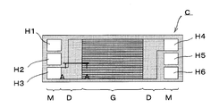
- a fuel cell (single cell) C shown in FIG. 1 includes a membrane electrode structure 2 having a frame 1 around it, and two separators 3 and 3 sandwiching the frame 1 and the membrane electrode structure 2.
- the frame 1 has a thin plate shape with a substantially constant thickness, and most of the frame 1 except the edge is thinner than the thickness of the membrane electrode structure 2. And it has the distribution area (diffuser part mentioned below) which distributes the gas for reaction between frame 1 and both separators 3 and 3. It is preferable that the frame 1 is a resin and the separator 3 is a metal because it is easy to manufacture.
- the membrane electrode structure 2 is generally called MEA (Membrane Electrode Assembly), and has a structure in which, for example, an electrolyte layer made of a solid polymer is sandwiched between an air electrode layer (cathode) and a fuel electrode layer (anode). Have.
- an oxidant gas (air) that is the other reaction gas is supplied to the air electrode layer, and a fuel gas (hydrogen) that is one reaction gas is supplied to the fuel electrode layer.
- Power is generated by an electrochemical reaction.
- the membrane electrode structure 2 includes those having a gas diffusion layer made of carbon paper or a porous body on the surfaces of the air electrode layer and the fuel electrode layer.
- the frame 1 is integrated with the membrane electrode structure 2 by resin molding (for example, injection molding).
- the frame 1 has a rectangular shape with the membrane electrode structure 2 in the center.
- the frame 1 has three manifold holes H1 to H6 arranged at both ends, and a region from each manifold hole group to the membrane electrode structure 2 is a reaction gas flow region.
- Each of the frame 1 and the separators 3 and 3 has a rectangular shape having substantially the same vertical and horizontal dimensions.
- Each separator 3 is formed by press-molding a metal plate such as stainless steel.
- Each separator 3 has a central portion corresponding to the membrane electrode structure 2 formed in a wave shape in a cross section in the short side direction. This wave shape is continuous in the long side direction as shown in the figure.
- each separator 3 has a convex portion in contact with the membrane electrode structure 2 at the central portion corresponding to the membrane electrode structure 2 in the wave shape, and the concave portions in the wave shape are flow paths for the reaction gas. It becomes.
- Each separator 3 has manifold holes H1 to H6 that are equivalent to the manifold holes H1 to H6 of the frame 1 at both ends, and the region from each manifold hole group to the corrugated section has a reaction gas flow. It becomes an area.
- the fuel cell C includes a power generation unit G that is a region of the membrane electrode structure 2 at the center. Further, on both sides of the power generation unit G, manifold units M and M that supply and discharge the reaction gas, and diffuser units D and D that are reaction gas flow regions from each manifold unit M to the power generation unit G are provided. It has become.
- the diffuser portion D which is a flow region for the reaction gas, is formed not only on both ends of the cell in FIG. 2, but also between the frame 1 and the separators 3 and 3 on both sides, that is, on the anode and cathode sides. ing.
- each of the manifold holes H1 to H3 is for supplying an oxidant gas (H1), for supplying a cooling fluid (H2), and for supplying a fuel gas (H3).
- H1 oxidant gas
- H2 cooling fluid
- H3 fuel gas
- the manifold holes H4 to H6 are for fuel gas discharge (H4), cooling fluid discharge (H5), and oxidant gas discharge (H6).
- Each flow path is formed in communication with each other in the stacking direction. The supply and discharge may be partially or entirely reversed in positional relationship.
- the fuel cell C is provided with a gas seal SL between the edges of the frame 1 and each separator 3 and around the manifold holes H1 to H6.
- a gas seal SL is also provided between cells, that is, between adjacent separators 3.
- a cooling fluid is circulated between the adjacent separators 3 and 3.
- the above gas seal SL hermetically separates the flow regions of the oxidant gas, the fuel gas, and the cooling fluid between the individual layers, and manifold holes H1 to H6 so that a predetermined fluid flows between the layers.
- An opening is provided at an appropriate location on the peripheral edge of the.
- a plurality of fuel cells C having the above-described configuration are stacked to form a fuel cell stack FS as shown in FIG.
- the fuel cell stack FS has a current collector plate 4A and a spacer at one end (right end in FIG. 3) in the cell stacking direction with respect to the stack A of the fuel cells C. 5 is provided with an end plate 6A, and the other end is provided with an end plate 6B via a current collecting plate 4B. Further, the fuel cell stack FS is provided with fastening plates 7A and 7B on both surfaces (upper and lower surfaces in FIG. 3) on the long side of the fuel cell C with respect to the laminate A, and the short side and Reinforcing plates 8A and 8B are provided on both sides.
- the fastening plates 7A and 7B and the reinforcing plates 8A and 8B are connected to both end plates 6A and 6B by bolts B.
- the fuel cell stack FS has a case-integrated structure as shown in FIG. 3B.
- the fuel cell stack FS is constrained and pressurized in the cell stacking direction to contact each fuel cell C with a predetermined contact surface. Apply pressure to maintain good gas sealing and conductivity.
- the fuel battery cell C is disposed on at least one of the opposing surfaces of the frame 1 and the separator 3 on the other side. While providing the protrusion 10 which contact
- the frame 1 in the diffuser portion D on the cathode side (upper side in the figure), the frame 1 is provided with a protrusion 10 that contacts the separator 3, and the separator 3 and the tip of the protrusion 10 are bonded (reference numeral).
- the frame 1 and the separator 3 are arranged apart from each other.
- the positions of the cathode and anode may be upside down.
- the protrusions 10 of this embodiment have a truncated cone shape, are integrally formed with the resin frame 1, and are arranged at predetermined intervals as shown in FIG.
- the protrusion 10 is not particularly limited in shape or the like, and may be any as long as it does not hinder the flow of the reaction gas.
- a protrusion 11 having a shape similar to that of the protrusion 10 is provided on the anode-side surface (the lower surface in FIG. 4) of the frame 1.
- the protrusion 11 is lower than the protrusion 10 on the cathode side and forms a gap between the separator 3 and abuts against the separator 3 when the frame 1 and the separator 3 are displaced in the approaching direction. To prevent excessive displacement.
- the frame 1 and the separator 3 are separated from each other in the anode-side diffuser portion D. Therefore, when the fuel cell stack FS is configured, the pressure in the stacking direction is mainly a membrane. It acts between the electrode structure 2 and the separator 3, and a sufficient contact surface pressure between the membrane electrode structure 2 and the separator 3 can be secured.
- the fuel cell C can absorb the displacement in the thickness direction by the gap between the frame 1 and the separator 3 in the diffuser portion D on the anode side. That is, the fuel cell C can absorb the dimensional tolerances and manufacturing variations of the components and the aging displacement in the thickness direction of the membrane electrode structure 2 through the gap. Thereby, when the fuel cell C constitutes the fuel cell stack FS, the fuel cell C can suppress variations in performance such as contact surface pressure and gas flow rate in individual cells.
- the durability of the membrane electrode structure 2 having the frame 1 is improved by bonding the tip of the protrusion 10 of the frame 1 and the separator 3 in the diffuser portion D on the cathode side. That is, in the fuel cell C, even if a gas differential pressure is generated between the cathode side and the anode side, the frame 1 is held by the separator 3 by the protrusion 10 bonded to the separator 3. Even when any pressure on the anode side becomes high, the displacement of the frame 1 can be suppressed. As a result, the fuel cell C can prevent the bending stress from concentrating on the joint between the frame 1 and the membrane electrode structure 2.
- the fuel cell C can absorb the displacement in the thickness direction by the gap provided between the frame 1 and the separator 3, and at the same time hold the frame 1 by the protrusion 10 bonded to the separator 3. Therefore, both the optimization of the performance of each cell when the fuel cell stack FS is configured and the improvement of the durability of the joint portion between the frame 1 and the membrane electrode structure 2 can be achieved.
- FIG. 5 is a diagram for explaining another embodiment of the fuel battery cell of the present invention.
- the same components as those of the previous embodiment shown in FIGS. 1 to 4 are denoted by the same reference numerals, and detailed description thereof is omitted.
- the upper side in the figure is described as the cathode side, but the positions of the cathode and the anode may be upside down.
- the separator 3 is provided with a protrusion 12 in contact with the frame 1 on the other side, and the frame 1 and the tip of the protrusion 12 are bonded ( Q) Yes.
- the protrusions 12 are arranged at predetermined intervals so as not to disturb the flow of the reaction gas, like the protrusions of the previous embodiment.
- the frame 1 and the separator 3 are spaced apart.
- the displacement in the thickness direction can be absorbed by the gap provided between the frame 1 and the separator 3 as in the previous embodiment, and at the same time, the fuel cell C is provided in the separator 3. Since the frame 1 is held by the protrusions 12, both the optimization of the performance of each cell when the fuel cell stack FS is configured and the improvement of the durability of the joint between the frame 1 and the membrane electrode structure 2 are achieved. be able to.
- FIG. 6 is a diagram for explaining still another embodiment of the fuel battery cell of the present invention.
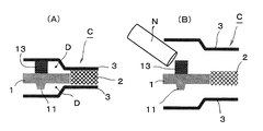
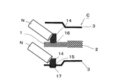
- a fuel battery cell C shown in FIG. 6A has a cathode-side diffuser portion D provided with a protrusion 13 in contact with the mating side on at least one of the opposing surfaces of the frame 1 and the separator 3.
- the protrusion 13 is formed of an adhesive interposed between the frame 1 and the separator 3. Even in the protrusions 13, they are arranged at predetermined intervals so as not to disturb the flow of the reaction gas.
- the frame 1 and the separator 3 are spaced apart.
- the adhesive forming the protrusion 13 can be selected from materials specialized in adhesive strength, and for example, an epoxy-based material can be used.
- the protrusion (adhesive material) 13 can be formed in a predetermined shape in advance, but more desirably, it is discharged from a nozzle N of an adhesive supply device (not shown) as shown in FIG. Apply to frame 1. And since the protrusion (adhesive material) 13 is bonded to both by joining the frame 1 and the separator 3, it is equivalent to bonding the separator 3 on the other side and the tip. Note that, contrary to the illustrated example, it is naturally possible to provide (apply) the protrusion 13 on the separator 3.
- the protrusions 13 are formed of an adhesive, so that the protrusions of the frame 1 and the separator 3 are eliminated.
- the shape can be simplified, and the protrusion 13 can be formed together with the step of providing the gas seal SL (see FIG. 1), which contributes to an improvement in production efficiency and a reduction in manufacturing cost. Can do.
- an adhesive such as silicone rubber, fluororubber, and polyolefin rubber.
- FIG. 7 is a view for explaining still another embodiment of the fuel battery cell of the present invention.
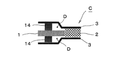
- a fuel cell C shown in FIG. 7A has a protrusion in contact with the mating side at least one of the opposing surfaces of the frame 1 and the separator 3 in the diffuser portion D on either the cathode side or the anode side. While providing the part 10, the diffuser part D of the other side is interposed between the flame
- the elastic bodies 14 are arranged at predetermined intervals so as not to disturb the flow of the reaction gas, like the protrusions of the previous embodiment.
- the fuel cell C is provided with a protrusion 10 in contact with the separator 3 on the frame 1 in the cathode-side diffuser portion D, and between the frame 1 and the separator 3 in the anode-side diffuser portion D. , An elastic body 14 in contact with both is interposed.
- the elastic body 14 can be provided on the separator 3 as shown in FIG. 7B or on the frame 1 as shown in FIG. 7C.
- the elastic body 14 can be formed in a predetermined shape in advance, but more preferably, it is formed of an adhesive that is applied in a molten state and has elasticity after being cured.
- the adhesive forming the elastic body 14 for example, a material such as silicone rubber, fluorine rubber, or polyolefin rubber can be used. Even in this elastic body (adhesive material) 14, it is applied to the frame 1 or the separator 3 in the same manner as the protrusion (reference numeral 13 in FIG. 6) formed by the previous adhesive material, and after curing, the frame 1 and the separator 3 are applied. Will be in contact with the other party.
- the fuel cell C described above absorbs displacement in the thickness direction through the gap between the anode-side separator 3 and the frame 1, whereas the anode-side elastic body 14. To absorb the displacement in the thickness direction.
- the fuel battery cell C holds the frame 1 by the protrusion 10 and the elastic body 14 of the frame 1.
- the elastic body 14 can be formed together with the step of providing the gas seal SL (see FIG. 1).
- the elastic body 14 and the gas seal SL can be formed of the same material, which can contribute to improvement in production efficiency and reduction in manufacturing cost.
- an adhesive such as silicone rubber, fluororubber, and polyolefin rubber.
- the adhesive has a low adhesive strength. But you can. Therefore, the surface treatment of the adhesive surface can be simplified or eliminated, and an inexpensive adhesive can be employed, thereby further reducing the manufacturing cost.
- FIG. 8 is a diagram for explaining still another embodiment of the fuel battery cell of the present invention.
- an elastic body 14 in contact with both is interposed between the frame 1 and the separator 3 in both of the diffuser portions D on the cathode side and the anode side. That is, in the diffuser portion D on the cathode side and the anode side, at least one of the opposing surfaces of the frame 1 and the separator 3 is provided with a protrusion that contacts the mating side.
- an elastic body 14 interposed between the separator 3 and the separator 3. Similar to the previous embodiment, the elastic bodies 14 are arranged at predetermined intervals so as not to disturb the flow of the reaction gas. Even in the elastic body 14, it is possible to form it into a predetermined shape in advance, but more desirably, it is formed of an adhesive material that is applied in a molten state and has elasticity after being cured.
- the fuel cell C described above absorbs displacement in the thickness direction by both elastic bodies 14 on the cathode side and the anode side, and holds the frame 1 by both elastic bodies 14.
- both the optimization of the performance of each cell when the fuel cell stack FS is configured and the improvement of the durability of the joint between the frame 1 and the membrane electrode structure 2 are achieved. Can do.
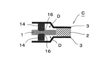
- both diffuser portions D are provided with elastic bodies 14, and a recess 15 (or 16) is formed on at least one of the opposing surfaces of the frame 1 and the separator 3.
- the elastic body 14 is disposed in the recess 15 (or 16).
- the elastic bodies 14 are arranged at predetermined intervals so as not to disturb the flow of the reaction gas, they are similarly formed at predetermined intervals even in the recesses 15 (or 16).
- a recess 15 is formed in the separator 3, and an elastic body 14 is disposed in the recess 15.
- the recessed part 15 can apply the back side part of the convex part 17 press-molded by the separator 3.
- FIG. 10 the fuel cell C shown in FIG. 10 has a recess 16 formed in the frame 1, and an elastic body 14 is disposed in the recess 16.
- the recess 16 can be formed by surface grinding such as sandblasting.
- Each of the fuel cells C described above performs displacement absorption in the thickness direction by both elastic bodies 14 and holds the frame 1 by both elastic bodies 14 to form a fuel cell stack FS, as in the previous embodiment.
- the optimization of the performance of each cell and the improvement of the durability of the joint between the frame 1 and the membrane electrode structure 2 can be achieved at the same time.
- the recesses 15 and 16 facilitate the positioning of the elastic body 14, which can contribute to the improvement of manufacturing efficiency and increase the contact area between the elastic body 14 and the frame 1 or the separator 3. Adhesive strength and stability will increase. Furthermore, in addition to improving the durability with stabilization of the elastic body 14, the expansion / contraction length of the elastic body 14 is increased by the depth of the recesses 15, 16, so the displacement absorption range in the thickness direction of the fuel cell C Can be increased.
- the convex portion 17 becomes a flow path forming portion of the cooling fluid. That is, since the fuel cell C has a structure in which the cooling fluid is circulated between the adjacent ones in the stacked state as described above, the portion for forming the flow path between the adjacent separators 3 is formed. And parts are required. Therefore, as in this embodiment, if the back side portion of the convex portion 17 press-molded in the separator 3 is a concave portion 15, the convex portion 17 for forming the flow path and the concave portion 15 for arranging the elastic body 14 are provided. It can be formed in one process and is very effective in terms of manufacturing efficiency and manufacturing cost.
- the concave portion 16 of the frame 1 is formed by surface grinding, and particularly if the surface texture is formed into fine irregularities by sandblasting, the adhesion area of the elastic body 14 is increased.
- the adhesive strength can be further increased, whereby the elastic body 14 can be prevented from peeling and the durability can be further increased.
- the elastic body 14 shown in FIGS. 7 to 10 can be formed in the same process as the gas seal SL (see FIG. 1) as shown in FIG.
- the elastic body 14 can be formed by injection molding, baking, or the like, but if an adhesive material that exhibits elasticity after curing is used as a material, the gas seal SL and the protrusion 13 shown in FIG. They can be formed with the same configuration (material) and are very effective in terms of manufacturing efficiency and manufacturing cost.
- FIG. 12 is a diagram for explaining still another embodiment of the fuel battery cell of the present invention.
- the illustrated fuel cell C has a recess 16 in the frame 1 at the diffuser portion D on the cathode side (upper side in the figure) and a recess 15 in the separator 3 at the diffuser portion D on the anode side (lower side in the figure).
- the concave portion 15 may be provided in the separator 3 in the cathode side diffuser portion D
- the concave portion 16 may be provided in the frame 1 in the anode side diffuser portion D.
- the recesses 15 and 16 may be provided on the surfaces facing the same direction, and preferably on the upper surface during assembly manufacturing.
- an adhesive material having elasticity after curing is used, and a molten adhesive material is discharged from a nozzle N of an adhesive material supply device (not shown) and applied to the recesses 15 and 16 and cured.
- the elastic body 14 is formed. Therefore, as shown in the illustrated example, if the recesses 15 and 16 are provided on the upper surface of the frame 1 and the separator 3 in both diffuser portions D, the molten adhesive can be applied from the same direction. In addition to being able to prevent the adhesive from flowing out, it is effective in terms of manufacturing efficiency, and the elastic system 14 can be formed well.
- the fuel cell C of the present invention has the optimized performance of each cell when the fuel cell stack FS is configured, and the joint between the frame 1 and the membrane electrode structure 2. It is possible to achieve both improved durability. Therefore, in the fuel cell stack FS formed by laminating a plurality of the above-described fuel cells C, the power generation performance and durability performance of each fuel cell C can be made uniform, and stable power generation can be performed over a long period of time. it can.
- the configuration of the fuel cell of the present invention is not limited to the above-described embodiments, and details of the configuration can be appropriately changed without departing from the gist of the present invention.
- an example in which the positions of the protrusions and the elastic body and the positions of the elastic body and the elastic body coincide with each other is illustrated. It may be shifted. It is also possible to combine the configurations of the above embodiments.
Landscapes
- Life Sciences & Earth Sciences (AREA)
- Engineering & Computer Science (AREA)
- Manufacturing & Machinery (AREA)
- Sustainable Development (AREA)
- Sustainable Energy (AREA)
- Chemical & Material Sciences (AREA)
- Chemical Kinetics & Catalysis (AREA)
- Electrochemistry (AREA)
- General Chemical & Material Sciences (AREA)
- Fuel Cell (AREA)
Abstract
Avec les piles à combustible de l'art antérieur, dans le cas d'une configuration par stratification et empilement de piles à combustible, il est difficile d'optimiser les propriétés de l'ensemble des cellules, et il existe des risques de baisse de durabilité d'une partie de liaison entre une armature de résine et une structure d'électrodes à membrane du fait d'une différence de pression entre un côté cathode et un côté anode. La pile à combustible de l'invention est équipée : de la structure d'électrodes à membrane (2) possédant l'armature (1); et de séparateurs (3) enserrant ceux-ci. La pile à combustible (C) possède des parties diffuseur (D) entre l'armature (1) et chacun des séparateurs. Au niveau de la partie diffuseur (D) de l'un des côté cathode ou anode, une partie saillie (10) en contact avec le côté opposé, est agencée sur une des faces de l'armature et du séparateur (3), et le côté opposé et l'extrémité avant de cette partie saillie (10) sont solidarisés; tandis qu'au niveau de la partie diffuseur (D) située de l'autre côté, l'armature (1) et le séparateur (3) sont disposés séparément. Ainsi, une optimisation des propriétés de chacune des piles (C) lorsqu'un empilement de piles à combustible (FS) est configuré, et une amélioration de la durabilité de la partie de liaison entre l'armature (1) et la structure d'électrodes à membrane (2), peuvent être conjointement réalisées.
Priority Applications (4)
| Application Number | Priority Date | Filing Date | Title |
|---|---|---|---|
| CA2831871A CA2831871A1 (fr) | 2011-03-31 | 2012-02-23 | Pile a combustible pour batterie a combustible |
| CN2012800082890A CN103354960A (zh) | 2011-03-31 | 2012-02-23 | 燃料电池单元 |
| EP12764856.6A EP2693547A4 (fr) | 2011-03-31 | 2012-02-23 | Pile à combustible |
| US14/007,282 US20140017593A1 (en) | 2011-03-31 | 2012-02-23 | Fuel battery cell |
Applications Claiming Priority (2)
| Application Number | Priority Date | Filing Date | Title |
|---|---|---|---|
| JP2011-077660 | 2011-03-31 | ||
| JP2011077660A JP5790083B2 (ja) | 2011-03-31 | 2011-03-31 | 燃料電池セル |
Publications (1)
| Publication Number | Publication Date |
|---|---|
| WO2012132666A1 true WO2012132666A1 (fr) | 2012-10-04 |
Family
ID=46930428
Family Applications (1)
| Application Number | Title | Priority Date | Filing Date |
|---|---|---|---|
| PCT/JP2012/054385 Ceased WO2012132666A1 (fr) | 2011-03-31 | 2012-02-23 | Pile à combustible |
Country Status (6)
| Country | Link |
|---|---|
| US (1) | US20140017593A1 (fr) |
| EP (1) | EP2693547A4 (fr) |
| JP (1) | JP5790083B2 (fr) |
| CN (1) | CN103354960A (fr) |
| CA (1) | CA2831871A1 (fr) |
| WO (1) | WO2012132666A1 (fr) |
Cited By (1)
| Publication number | Priority date | Publication date | Assignee | Title |
|---|---|---|---|---|
| CN104854749A (zh) * | 2012-12-13 | 2015-08-19 | 日产自动车株式会社 | 燃料电池堆及使用了该燃料电池堆的载荷分担方法 |
Families Citing this family (19)
| Publication number | Priority date | Publication date | Assignee | Title |
|---|---|---|---|---|
| JP5907053B2 (ja) * | 2012-12-13 | 2016-04-20 | トヨタ自動車株式会社 | 燃料電池セル |
| JP6150040B2 (ja) * | 2013-03-22 | 2017-06-21 | 日産自動車株式会社 | 燃料電池及び燃料電池スタック |
| JP6068218B2 (ja) * | 2013-03-22 | 2017-01-25 | 本田技研工業株式会社 | 燃料電池の運転方法 |
| JP6115632B2 (ja) * | 2013-04-22 | 2017-05-10 | 日産自動車株式会社 | 燃料電池スタックのセル構造 |
| JP6123730B2 (ja) * | 2014-04-23 | 2017-05-10 | トヨタ自動車株式会社 | 燃料電池 |
| CA3001093C (fr) * | 2015-10-05 | 2019-03-12 | Nissan Motor Co., Ltd. | Empilement de piles a combustible presentant une portion chevauchante servant a transmettre et supporter une force de reaction |
| WO2017190565A1 (fr) * | 2016-05-06 | 2017-11-09 | 安徽巨大电池技术有限公司 | Bloc-batterie et élément de batterie associé |
| DE102017112529B4 (de) * | 2016-06-10 | 2023-01-05 | Toyota Jidosha Kabushiki Kaisha | Einzelzelle einer Brennstoffzelle |
| JP6628166B2 (ja) * | 2016-07-14 | 2020-01-08 | 日産自動車株式会社 | 燃料電池スタック |
| JP6521912B2 (ja) | 2016-07-25 | 2019-05-29 | トヨタ自動車株式会社 | 燃料電池単セルおよびその製造方法 |
| JP6834737B2 (ja) * | 2017-04-17 | 2021-02-24 | トヨタ自動車株式会社 | 燃料電池 |
| JP7003682B2 (ja) * | 2018-01-22 | 2022-02-04 | トヨタ自動車株式会社 | 燃料電池の製造方法 |
| JP7031526B2 (ja) * | 2018-08-06 | 2022-03-08 | トヨタ自動車株式会社 | 燃料電池セルの製造装置 |
| DE202018104628U1 (de) * | 2018-08-10 | 2019-12-24 | Reinz-Dichtungs-Gmbh | Elektrochemisches System |
| JP7115451B2 (ja) * | 2019-09-30 | 2022-08-09 | トヨタ自動車株式会社 | 燃料電池単位セル |
| JP7120197B2 (ja) * | 2019-09-30 | 2022-08-17 | トヨタ自動車株式会社 | 燃料電池単位セル |
| JP7115450B2 (ja) * | 2019-09-30 | 2022-08-09 | トヨタ自動車株式会社 | 燃料電池単位セル |
| KR20210076468A (ko) * | 2019-12-16 | 2021-06-24 | 현대자동차주식회사 | 연료전지용 탄성체 셀 프레임 및 그 제조방법과 이를 이용한 단위 셀 |
| EP4181245A1 (fr) * | 2021-11-12 | 2023-05-17 | AVL List GmbH | Dispositif de châssis pour une pile à combustible et dispositif de pile à combustible le comprenant |
Citations (4)
| Publication number | Priority date | Publication date | Assignee | Title |
|---|---|---|---|---|
| JP2003077499A (ja) | 2001-06-18 | 2003-03-14 | Toyota Motor Corp | 燃料電池 |
| JP2007305325A (ja) * | 2006-05-09 | 2007-11-22 | Toyota Motor Corp | 燃料電池 |
| JP2007328969A (ja) * | 2006-06-07 | 2007-12-20 | Toyota Motor Corp | 燃料電池 |
| JP2009224275A (ja) * | 2008-03-18 | 2009-10-01 | Toyota Motor Corp | 燃料電池用セパレータ及びその製造方法並びに燃料電池 |
Family Cites Families (3)
| Publication number | Priority date | Publication date | Assignee | Title |
|---|---|---|---|---|
| JP3489181B2 (ja) * | 1994-03-10 | 2004-01-19 | トヨタ自動車株式会社 | 燃料電池の単電池およびその製造方法 |
| JP2009104882A (ja) * | 2007-10-23 | 2009-05-14 | Toyota Motor Corp | 燃料電池 |
| CA2802412C (fr) * | 2010-06-15 | 2015-04-07 | Nissan Motor Co., Ltd. | Pile a combustible avec pression de surface de contact amelioree |
-
2011
- 2011-03-31 JP JP2011077660A patent/JP5790083B2/ja active Active
-
2012
- 2012-02-23 WO PCT/JP2012/054385 patent/WO2012132666A1/fr not_active Ceased
- 2012-02-23 US US14/007,282 patent/US20140017593A1/en not_active Abandoned
- 2012-02-23 CN CN2012800082890A patent/CN103354960A/zh active Pending
- 2012-02-23 EP EP12764856.6A patent/EP2693547A4/fr not_active Withdrawn
- 2012-02-23 CA CA2831871A patent/CA2831871A1/fr not_active Abandoned
Patent Citations (4)
| Publication number | Priority date | Publication date | Assignee | Title |
|---|---|---|---|---|
| JP2003077499A (ja) | 2001-06-18 | 2003-03-14 | Toyota Motor Corp | 燃料電池 |
| JP2007305325A (ja) * | 2006-05-09 | 2007-11-22 | Toyota Motor Corp | 燃料電池 |
| JP2007328969A (ja) * | 2006-06-07 | 2007-12-20 | Toyota Motor Corp | 燃料電池 |
| JP2009224275A (ja) * | 2008-03-18 | 2009-10-01 | Toyota Motor Corp | 燃料電池用セパレータ及びその製造方法並びに燃料電池 |
Non-Patent Citations (1)
| Title |
|---|
| See also references of EP2693547A4 |
Cited By (2)
| Publication number | Priority date | Publication date | Assignee | Title |
|---|---|---|---|---|
| CN104854749A (zh) * | 2012-12-13 | 2015-08-19 | 日产自动车株式会社 | 燃料电池堆及使用了该燃料电池堆的载荷分担方法 |
| CN104854749B (zh) * | 2012-12-13 | 2016-08-24 | 日产自动车株式会社 | 燃料电池堆及使用了该燃料电池堆的载荷分担方法 |
Also Published As
| Publication number | Publication date |
|---|---|
| US20140017593A1 (en) | 2014-01-16 |
| CA2831871A1 (fr) | 2012-10-04 |
| EP2693547A4 (fr) | 2015-03-18 |
| JP5790083B2 (ja) | 2015-10-07 |
| JP2012212560A (ja) | 2012-11-01 |
| CN103354960A (zh) | 2013-10-16 |
| EP2693547A1 (fr) | 2014-02-05 |
Similar Documents
| Publication | Publication Date | Title |
|---|---|---|
| JP5790083B2 (ja) | 燃料電池セル | |
| JP5516917B2 (ja) | 燃料電池セル | |
| CN102484264B (zh) | 燃料电池单元 | |
| JP5615875B2 (ja) | 燃料電池用樹脂枠付き電解質膜・電極構造体 | |
| CN102918699B (zh) | 燃料电池单元 | |
| CA2910082C (fr) | Structure isolante, pile a combustible et empilement de piles a combustible | |
| JP2011222393A (ja) | 燃料電池 | |
| JP2013098155A (ja) | 燃料電池用樹脂枠付き電解質膜・電極構造体及び燃料電池スタック | |
| US9318753B2 (en) | Fuel cell | |
| JP2008171613A (ja) | 燃料電池 | |
| JP2012212611A (ja) | 燃料電池セル | |
| JP2015035311A (ja) | フレーム付き膜電極接合体、燃料電池単セル及び燃料電池スタック | |
| WO2012137820A1 (fr) | Pile à combustible | |
| EP2696414B1 (fr) | Pile à combustible | |
| JP6229339B2 (ja) | 燃料電池スタック | |
| JP2014186823A (ja) | 燃料電池及び燃料電池スタック | |
| JP2014229577A (ja) | 燃料電池用のセパレータ | |
| JP6150060B2 (ja) | フレーム付き膜電極接合体、燃料電池用単セル及び燃料電池スタック | |
| CA3030811A1 (fr) | Empilement de piles a combustible resistant a la pression equipe de separateurs | |
| JP2011048970A (ja) | 燃料電池 | |
| JP2018181533A (ja) | 燃料電池スタックおよび燃料電池スタックの製造方法 | |
| JP7070291B2 (ja) | 燃料電池スタック | |
| JP2017050206A (ja) | 燃料電池 | |
| JP2019192326A (ja) | 燃料電池の製造方法 |
Legal Events
| Date | Code | Title | Description |
|---|---|---|---|
| 121 | Ep: the epo has been informed by wipo that ep was designated in this application |
Ref document number: 12764856 Country of ref document: EP Kind code of ref document: A1 |
|
| WWE | Wipo information: entry into national phase |
Ref document number: 2012764856 Country of ref document: EP |
|
| WWE | Wipo information: entry into national phase |
Ref document number: 14007282 Country of ref document: US |
|
| ENP | Entry into the national phase |
Ref document number: 2831871 Country of ref document: CA |
|
| NENP | Non-entry into the national phase |
Ref country code: DE |