WO2012132761A1 - Unité d'aiguille d'injection, étui de stockage, ensemble d'aiguille d'injection et dispositif d'injection de médicament - Google Patents
Unité d'aiguille d'injection, étui de stockage, ensemble d'aiguille d'injection et dispositif d'injection de médicament Download PDFInfo
- Publication number
- WO2012132761A1 WO2012132761A1 PCT/JP2012/055362 JP2012055362W WO2012132761A1 WO 2012132761 A1 WO2012132761 A1 WO 2012132761A1 JP 2012055362 W JP2012055362 W JP 2012055362W WO 2012132761 A1 WO2012132761 A1 WO 2012132761A1
- Authority
- WO
- WIPO (PCT)
- Prior art keywords
- needle
- needle hub
- engaged
- storage case
- syringe
- Prior art date
- Legal status (The legal status is an assumption and is not a legal conclusion. Google has not performed a legal analysis and makes no representation as to the accuracy of the status listed.)
- Ceased
Links
Images






Classifications
-
- A—HUMAN NECESSITIES
- A61—MEDICAL OR VETERINARY SCIENCE; HYGIENE
- A61M—DEVICES FOR INTRODUCING MEDIA INTO, OR ONTO, THE BODY; DEVICES FOR TRANSDUCING BODY MEDIA OR FOR TAKING MEDIA FROM THE BODY; DEVICES FOR PRODUCING OR ENDING SLEEP OR STUPOR
- A61M5/00—Devices for bringing media into the body in a subcutaneous, intra-vascular or intramuscular way; Accessories therefor, e.g. filling or cleaning devices, arm-rests
- A61M5/46—Devices for bringing media into the body in a subcutaneous, intra-vascular or intramuscular way; Accessories therefor, e.g. filling or cleaning devices, arm-rests having means for controlling depth of insertion
-
- A—HUMAN NECESSITIES
- A61—MEDICAL OR VETERINARY SCIENCE; HYGIENE
- A61M—DEVICES FOR INTRODUCING MEDIA INTO, OR ONTO, THE BODY; DEVICES FOR TRANSDUCING BODY MEDIA OR FOR TAKING MEDIA FROM THE BODY; DEVICES FOR PRODUCING OR ENDING SLEEP OR STUPOR
- A61M5/00—Devices for bringing media into the body in a subcutaneous, intra-vascular or intramuscular way; Accessories therefor, e.g. filling or cleaning devices, arm-rests
- A61M5/002—Packages specially adapted therefor, e.g. for syringes or needles, kits for diabetics
-
- A—HUMAN NECESSITIES
- A61—MEDICAL OR VETERINARY SCIENCE; HYGIENE
- A61M—DEVICES FOR INTRODUCING MEDIA INTO, OR ONTO, THE BODY; DEVICES FOR TRANSDUCING BODY MEDIA OR FOR TAKING MEDIA FROM THE BODY; DEVICES FOR PRODUCING OR ENDING SLEEP OR STUPOR
- A61M5/00—Devices for bringing media into the body in a subcutaneous, intra-vascular or intramuscular way; Accessories therefor, e.g. filling or cleaning devices, arm-rests
- A61M5/178—Syringes
- A61M5/31—Details
- A61M5/32—Needles; Details of needles pertaining to their connection with syringe or hub; Accessories for bringing the needle into, or holding the needle on, the body; Devices for protection of needles
- A61M5/34—Constructions for connecting the needle, e.g. to syringe nozzle or needle hub
- A61M5/347—Constructions for connecting the needle, e.g. to syringe nozzle or needle hub rotatable, e.g. bayonet or screw
Definitions
- the present invention relates to an injection needle assembly that punctures a needle tip from the surface of the skin, a storage case that stores the injection needle assembly, an injection needle unit that includes the injection needle assembly and the storage case, and a drug injection device.
- the syringe needle assembly is housed in a storage case made of a hard material such as plastic until the needle tube tip is used. Protect. Then, a syringe is connected to the injection needle assembly, and the injection needle assembly is removed from the storage case for use.
- the injection needle assembly and the syringe are integrally connected by screwing a screw portion provided in the syringe and a screw groove provided in the injection needle assembly.
- Patent Literature 1 discloses an injection needle set including such an injection needle assembly and a storage case.
- a convex portion is provided on the outer peripheral surface of the needle hub that holds the needle tube, and a concave portion that engages with the convex portion is formed on the inner peripheral surface of the storage case that stores the needle hub.
- the convex portion and the concave portion are engaged with each other to prevent the liquid introduction tool, which is an injection needle assembly, from rotating with respect to the storage case.
- the skin is composed of three parts: epidermis, dermis, and subcutaneous tissue.
- the epidermis is a layer of about 50 to 200 ⁇ m from the skin surface, and the dermis is a layer of about 1.5 to 3.5 mm continuing from the epidermis.
- Influenza vaccines are generally administered subcutaneously or intramuscularly, and are therefore administered in the lower layer of the skin or deeper.
- the upper skin layer refers to the epidermis and dermis of the skin.
- drug administration to the upper layer of the skin requires a higher injection pressure than subcutaneous administration. Therefore, when a drug is administered to the upper skin portion, it is necessary to firmly connect the injection needle assembly and the syringe in order to prevent the drug solution from leaking from the connection portion between the injection needle assembly and the syringe.
- the present invention has been made in view of such a situation, and when connecting the injection needle assembly and the syringe, the threaded portion is prevented from being broken and the injection needle assembly and the syringe are firmly connected.
- the purpose is to be able to connect.
- An injection needle unit is provided on a side surface of a needle hub having a needle tube having a needle point to be punctured into the skin, a needle hub that holds the needle tube and is screwed with a screw portion of a syringe, and the needle hub. And an engaging portion.
- a cylindrical case body that houses the needle hub, and a housing that is provided in the case body and that engages with the engaging portion to restrict rotation of the needle hub about the axial direction of the needle tube. And a case.
- the engaging portion and the engaged portion are released from each other when a predetermined load is applied around the axial direction.
- the predetermined load is, for example, 5 to 50 cN ⁇ m.
- the predetermined load for disengaging the engaging portion and the engaged portion is larger than the frictional resistance generated when the screw portion of the syringe and the screw groove of the needle hub are screwed together, and the screw portion and the screw groove are tightened.
- the load is set smaller than the load at which the thread portion and the thread groove are broken.
- An injection needle assembly of the present invention includes a needle tube having a needle tip that is punctured into the skin, a needle hub that holds the needle tube and is screwed with a screw portion of a syringe, and is housed in a storage case; It has. Also, an engagement portion is provided on a side surface portion of the needle hub, engages with an engaged portion provided on the storage case, and restricts rotation of the needle hub around the axial direction of the needle tube. The engaging portion is disengaged from the engaged portion when a predetermined load is applied around the axial direction.
- the storage case of the present invention has a substantially cylindrical case main body that stores the needle hub, and is engaged with an engagement portion provided on the needle main body, and about the axial direction of the needle tube in the needle hub. And an engaged portion for restricting rotation of the. Then, when a predetermined load is applied around the axial direction, the engaged portion is disengaged from the engaging portion.
- the drug injection device of the present invention includes a syringe having a threaded portion, a needle tube having a needle tip that is punctured into the skin, a needle hub having a thread groove that holds the needle tube and is screwed with the threaded portion, and a needle hub And an engaging portion provided on the side surface portion.
- the engagement portion provided in the needle hub and the engaged portion provided in the storage case are engaged, whereby the screw of the needle hub When the groove and the screw portion of the syringe are screwed together, the needle hub can be restricted from rotating. Thereby, a needle hub and a syringe can be connected firmly and it can prevent that a chemical
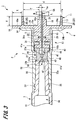
- FIG. 1 is an exploded perspective view of a first embodiment of a drug injection device of the present invention. It is the disassembled perspective view which looked at 1st Embodiment of the chemical injection device of this invention from the back side. It is sectional drawing which shows the state which removed the storage case from the 1st Example of the pharmaceutical injection device of this invention. It is sectional drawing which shows the example of 1st Embodiment of the injection needle unit of this invention.
- FIG. 5A is a cross-sectional view of the injection needle assembly and the storage case according to the first embodiment of the pharmaceutical injection device of the present invention as seen from the bottom surface side of the storage case, and FIG. It is explanatory drawing which shows. 6A is a top view of the first embodiment of the storage case of the present invention, and FIG.
- FIG. 6B is a front view of the first embodiment of the injection needle assembly.
- FIG. 7A is a top view of a second embodiment of the storage case of the present invention, and FIG. 7B is a front view of the second embodiment of the injection needle assembly.
- FIG. 8A is a top view of the third embodiment of the storage case of the present invention, and FIG. 8B is a front view of the third embodiment of the injection needle assembly. It is sectional drawing which shows the storage case concerning the 4th Example of the injection needle unit of this invention. It is a top view which shows the storage case concerning the 4th Example of the injection needle unit of this invention. It is a side view which shows the injection needle assembly and storage case concerning the 4th Example of the injection needle unit of this invention.
- FIG. 12A and 12B are views showing a state in which the injection needle assembly is stored in the storage case in the fourth embodiment of the injection needle unit of the present invention
- FIG. 12A is a sectional view
- FIG. is there.
- FIG. 13A is a cross-sectional view
- FIG. 13B is an enlarged view of a main part of the fourth embodiment of the injection needle unit of the present invention when the injection needle assembly is stored in the storage case from another angle. It is explanatory drawing shown.
- Embodiments of a needle assembly and a drug injection device according to the present invention will be described below with reference to FIGS.
- symbol is attached
- the present invention is not limited to the following form. The description will be given in the following order.
- First Embodiment 1-1 Configuration example of drug injection device 1-2. Assembling method of injection needle unit 1-3. Assembly method of drug injection device 1-4. 1. Method of using drug injection device 2.
- FIG. 1 is an exploded perspective view of the drug injection device of this example as viewed from the front side.
- FIG. 2 is an exploded view of the drug injection device of this example as viewed from the back side.
- the drug injection device 1 is used when the needle tip is punctured from the skin surface and the drug is injected into the upper layer of the skin.
- the upper skin layer refers to the epidermis and dermis of the skin.
- the drug injection device 1 includes an injection needle assembly 2, a syringe 3 to which the injection needle assembly 2 is detachably connected, and a storage in which the injection needle assembly 2 is stored.
- the case 8 is constituted.
- the injection needle assembly 2 and the storage case 8 constitute an injection needle unit 4 (see FIG. 4).
- the syringe 3 may be one that is filled with a medicine when the medicine injection device is used, or may be a prefilled syringe that is filled with a medicine in advance. Moreover, as a medicine with which the syringe 3 is filled, a vaccine can be mentioned, but a medicine using a high-molecular substance such as a cytokine or a hormone may be used.
- the injection needle assembly 2 includes a hollow needle tube 5 having a needle hole, a needle hub 6 to which the needle tube 5 is fixed, and an elastic member 7 disposed in the needle hub 6. Yes.
- the needle hub 6 includes a first member 11 that holds the needle tube 5 and a second member 12 into which a later-described discharge portion 52 of the syringe 3 is inserted.
- FIG. 3 is a cross-sectional view of the medicine injection device 1
- FIG. 4 is a cross-sectional view showing the injection needle unit 4.
- FIG. 5A is a view of the injection needle assembly 2 and the storage case 8 as viewed from the bottom surface side of the storage case 8, and
- FIG. 5B is an explanatory view showing an enlarged main part.
- FIG. 6B is a front view of the injection needle assembly 2.
- the needle tube 5 of the injection needle assembly 2 has a size of 26 to 33 gauge (outer diameter 0.2 to 0.45 mm) based on the ISO medical needle tube standard (ISO9626: 1991 / Amd.1: 2001 (E)). Those of 30 to 33 gauge are preferably used.
- a needle tip 5A having a blade surface 5a is provided at one end of the needle tube 5.
- the other end of the needle tube 5 opposite to the needle tip 5A is referred to as a “base end 5B”.
- the axial length of the needle tube 5 on the blade surface 5a (hereinafter referred to as “bevel length B”) may be 1.4 mm (adult) or less, which is the thinnest thickness of the upper skin layer described later.
- the bevel length may be about 0.5 mm or more when a short bevel is formed on a 33 gauge needle tube. That is, the bevel length B is preferably set in the range of 0.5 to 1.4 mm.
- the bevel length B is more preferable if the thinnest thickness of the upper skin portion is 0.9 mm (child) or less, that is, the bevel length B is in the range of 0.5 to 0.9 mm.
- the short bevel refers to a blade surface that is generally used for injection needles and forms an angle of 18 to 25 ° with respect to the longitudinal direction of the needle.
- the material of the needle tube 5 examples include stainless steel, but are not limited thereto, and aluminum, aluminum alloy, titanium, titanium alloy, and other metals can be used.
- the needle tube 5 can be not only a straight needle but also a tapered needle at least partially tapered.
- the proximal end portion has a larger diameter than the needle distal end portion, and the intermediate portion may have a tapered structure.
- the cross-sectional shape of the needle tube 5 may be not only a circle but also a polygon such as a triangle.
- the first member 11 and the second member 12 of the needle hub 6 are formed as separate members.
- the second member 12 is connected to the first member 11 that holds the needle tube 5.
- Examples of the material of the first member 11 and the second member 12 include synthetic resins such as polycarbonate, polypropylene, and polyethylene.
- the first member 11 includes a base portion 15, an adjustment portion 16, a stabilization portion 17, and a guide portion 18.
- the base portion 15 is formed in a substantially columnar shape, and has end faces 15a and 15b perpendicular to the axial direction.
- the adjustment portion 16 is provided at the center of the end surface 15 a of the base portion 15, and includes a columnar convex portion that protrudes in the axial direction of the base portion 15.
- the axis of the adjustment portion 16 is coincident with the axis of the base portion 15.
- a through-hole 21 through which the needle tube 5 passes is provided in the axial center of the base portion 15 and the adjustment portion 16.
- the base portion 15 is provided with an injection hole 22 for injecting the adhesive 20 into the through hole 21.
- the injection hole 22 is opened on the outer peripheral surface of the base portion 15 and communicates with the through hole 21. That is, the needle tube 5 is fixed to the base portion 15 by the adhesive 20 injected from the injection hole 22 into the through hole 21.
- the proximal end 5B side of the needle tube 5 protrudes from the end face 15b of the base portion 15.
- the base portion 15 is inserted into the second member 12 from the end surface 15b side, and the proximal end 5B side of the needle tube 5 is inserted into an insertion hole 45 described later of the elastic member 7.
- the end surface 15b of the base part 15 is contact
- a connecting piece 24 is provided on the outer peripheral surface of the base portion 15.
- the connection piece 24 is formed as a ring-shaped flange protruding in the radial direction of the base portion 15, and has flat surfaces 24 a and 24 b that face the axial direction of the base portion 15.
- the second member 12 is connected to the flat surface 24 b of the connection piece 24.
- the distal end portion of the connection piece 24 is a guide portion 18. The guide portion 18 will be described in detail later.
- the end surface of the adjusting portion 16 is a needle projecting surface 16a from which the needle tip 5A side of the needle tube 5 projects.
- the needle projecting surface 16 a is formed as a plane orthogonal to the axial direction of the needle tube 5.
- This needle protrusion surface 16a defines the depth at which the needle tube 5 is punctured by contacting the surface of the skin when the needle tube 5 is punctured into the upper layer portion of the skin. That is, the depth at which the needle tube 5 is punctured into the upper skin layer is determined by the length of the needle tube 5 protruding from the needle protruding surface 16a (hereinafter referred to as “projection length L”).
- the thickness of the upper skin portion corresponds to the depth from the skin surface to the dermis layer, and is generally in the range of 0.5 to 3.0 mm. Therefore, the protruding length L of the needle tube 5 can be set in the range of 0.5 to 3.0 mm.
- the vaccine is generally administered to the upper arm portion, but when used for administration to the upper skin portion, the shoulder peripheral portion where the skin is thick, particularly the deltoid region is preferred. Therefore, the thickness of the upper layer of the deltoid muscle was measured for 19 children and 31 adults. This measurement was performed by imaging the upper layer of the skin with high ultrasonic reflectivity using an ultrasonic measurement device (NP60R-UBM, high-resolution echo for small animals, Nepagene). In addition, since the measured value was logarithmic normal distribution, the range of MEAN ⁇ 2SD was obtained by geometric mean.
- the thickness of the upper skin layer of the deltoid muscle of the child was 0.9 to 1.6 mm.
- the thickness of the upper skin layer of the deltoid muscle of adults was 1.4 to 2.6 mm at the distal part, 1.4 to 2.5 mm at the central part, and 1.5 to 2.5 mm at the proximal part. It was. From the above, it was confirmed that the thickness of the upper skin layer in the deltoid muscle was 0.9 mm or more in the case of children and 1.4 mm or more in the case of adults. Therefore, in the injection in the upper layer part of the deltoid muscle, the protruding length L of the needle tube 5 is preferably set in the range of 0.9 to 1.4 mm.
- the blade surface 5a of the needle tip 5A can be reliably positioned on the upper skin layer.
- the needle hole (chemical solution discharge port) that opens in the blade surface 5a can be located in the upper skin layer portion at any position in the blade surface 5a. Even if the drug solution outlet is located in the upper skin layer, if the needle tip 5A is deeply stabbed into the upper skin layer, the drug solution flows subcutaneously between the side surface of the end of the needle tip 5A and the cut skin. Therefore, it is important that the blade surface 5a is surely in the upper skin portion.
- the needle projecting surface 16a is formed so that the distance S from the peripheral edge to the outer peripheral surface of the needle tube 5 is 1.4 mm or less, preferably in the range of 0.3 to 1.4 mm.
- the distance S from the peripheral edge of the needle protruding surface 16a to the peripheral surface of the needle tube 5 is set in consideration of the pressure applied to the blisters formed by administering the drug to the upper skin layer. That is, the needle projecting surface 16a is set to a size that is sufficiently smaller than the blisters formed on the upper layer portion of the skin and does not hinder the formation of blisters. As a result, even if the needle protruding surface 16a presses the skin around the needle tube 5, it is possible to prevent the administered medicine from leaking.
- the stabilizing portion 17 is formed in a cylindrical shape protruding from the flat surface 24 a of the connecting piece 24 provided on the base portion 15.
- the needle tube 5 and the adjustment unit 16 are disposed in the cylindrical hole of the stabilization unit 17. That is, the stabilizing portion 17 is formed in a cylindrical shape that covers the periphery of the adjusting portion 16 through which the needle tube 5 passes, and is provided away from the needle tip 5A of the needle tube 5 in the radial direction.
- the end surface 17a of the stabilizing portion 17 is located closer to the proximal end 5B of the needle tube 5 than the needle protruding surface 16a of the adjusting portion 16.
- the needle projecting surface 16a first contacts the surface of the skin, and then contacts the end surface 17a of the stabilizing portion 17.
- the drug injection device 1 is stabilized by the end surface 17a of the stabilizing portion 17 coming into contact with the skin, and the needle tube 5 can be maintained in a posture substantially perpendicular to the skin.
- the needle tube 5 is skinned. It is possible to keep the posture substantially perpendicular to the angle.
- the axial distance between the end surface 17a of the stable portion 17 and the needle protruding surface 16a is preferably set to 1.3 mm or less.
- the inner diameter d of the stable portion 17 is set to a value equal to or larger than the diameter of the blister formed on the skin.
- the distance T from the inner wall surface of the stabilizing portion 17 to the peripheral edge of the needle protruding surface 16a is set to be in the range of 4 mm to 15 mm. Thereby, it can prevent that blister formation is inhibited by pressure being applied to a blister from the inner wall surface of stable part 17.
- the distance T from the inner wall surface of the stabilizing portion 17 to the periphery of the needle protruding surface 16a is not particularly limited as long as it is 4 mm or more. However, when the distance T is increased, the outer diameter of the stable portion 17 increases, so that it becomes difficult to bring the entire end surface 17a of the stable portion 17 into contact with the skin when the needle tube 5 is punctured into a thin arm like a child. . For this reason, the distance T is preferably set to 15 mm as a maximum in consideration of the thinness of the child's arm.
- the adjusting unit 16 does not enter the skin. Therefore, considering the distance T (4 mm or more) from the inner wall surface of the stable portion 17 to the periphery of the needle protruding surface 16a and the diameter (about 0.3 mm) of the needle protruding surface 16a, the inner diameter d of the stable portion 17 is 9 mm or more. Can be set.
- an engaging portion 25 is provided on the inner wall surface of the stabilizing portion 17.
- the engaging portion 25 is composed of four protrusions 26 formed at intervals in the circumferential direction of the inner wall surface of the stabilizing portion 17.
- the protrusion 26 has a substantially trapezoidal cross section.
- this engaging part 25 engages with the to-be-engaged part 67 provided in the storage case 8 mentioned later.
- the number of protrusions 26 may be three or less, or five or more.
- the cross-sectional shape of the protrusion 26 is not limited to a substantially trapezoidal shape, and may be formed in various other shapes such as a substantially triangular shape or a substantially semicircular shape.
- the guide portion 18 is a portion on the tip side of the connecting piece 24 with respect to the stabilizing portion 17.
- the guide portion 18 has a contact surface 18a that comes into contact with the skin.
- the contact surface 18 a is a part of the flat surface 24 a of the connection piece 24, and is a flat surface that is substantially parallel to the end surface 17 a of the stabilizing portion 17.
- the distance Y from the contact surface 18a of the guide portion 18 to the end surface 17a of the stable portion 17 punctures the needle tube 5 and the stable portion 17 by pressing the skin with an appropriate pressing force. Its length is set so that it can.
- the guide portion 18 guides the pressing force applied to the skin by the needle tube 5 and the stabilizing portion 17, and the needle tip 5A (blade surface 5a) of the needle tube 5 can be reliably positioned on the upper layer portion of the skin. Can give you a sense of security.
- An appropriate pressing force of the needle tube 5 and the stabilizing portion 17 is, for example, 3 to 20N.
- the guide portion height Y is the length from the tip surface of the guide portion 18 to the outer peripheral surface of the stable portion 17 (hereinafter referred to as “guide portion length”) X. It is determined appropriately based on the above. For example, when the inner diameter d of the stabilizing portion 17 is 12 mm and the guide portion length X is 3 mm, the guide portion height Y is set in the range of 2.3 to 6.6 mm.
- the engaging portion 25 may be formed on the outer peripheral surface of the stabilizing portion 17 or the outer peripheral surface of the guide portion 18.
- the second member 12 is formed in a substantially cylindrical shape.
- One end portion of the second member 12 in the axial direction is an insertion portion 31 into which the base portion 15 of the first member 11 is inserted, and the other end portion is in the insertion portion 32 into which the discharge portion 52 of the syringe 3 is inserted. It has become.
- the cylindrical hole 31 a of the insertion portion 31 is set to a size corresponding to the base portion 15 of the first member 11.
- the insertion part 31 is provided with a fixing piece 34 connected to the connection piece 24 of the first member 11.
- the fixing piece 34 is formed as a ring-shaped flange that protrudes radially outward continuously from the distal end of the insertion portion 31.
- a flat surface 24b of the connection piece 24 provided on the first member 11 is brought into contact with and fixed to the fixed piece 34.
- Examples of the fixing method of the fixing piece 34 and the connection piece 24 include an adhesive, ultrasonic welding, laser welding, and a fixing screw.
- the cylinder hole 32a of the insertion portion 32 is set to a size corresponding to the discharge portion 52 of the syringe 3, and the diameter continuously decreases toward the insertion portion 31 side.
- a thread groove 35 for screwing the discharge portion 52 of the syringe 3 is provided on the inner surface of the fitting portion 32 that forms the cylindrical hole 32a.
- the main body side engaging part 37 is formed as a stepped portion protruding radially inward from the inner surface of the second member 12, and has engaging surfaces 37 a and 37 b that are substantially orthogonal to the axial direction of the second member 12. ing.
- a flange portion 42 (to be described later) of the elastic member 7 is engaged with the engaging surface 37a of the main body side engaging portion 37, and a stopper protrusion 43 of the elastic member 7 is engaged with the engaging surface 37b.
- the elastic member 7 is made of an elastically deformable member.
- Examples of the material of the elastic member 7 include various rubber materials such as natural rubber, silicone rubber and isobutylene rubber, various thermoplastic elastomers such as polyurethane and styrene, or mixtures thereof.
- the elastic member 7 is disposed in the second member 12 of the needle hub 6 and is interposed between the first member 11 and the syringe 3. Then, a gap generated between the outer peripheral surface of the needle tube 5 protruding from the first member 11 on the proximal end 5B side and the second member 12 is filled.
- the elastic member 7 includes a main body 41, a flange 42 provided at one end of the main body 41 in the axial direction, and a stopper protrusion 43 provided at the other end of the main body 41.
- the main body 41 is formed in a substantially cylindrical shape and has end faces 41a and 41b perpendicular to the axial direction.
- the end surface 41a of the base member 15 of the first member 11 is in contact with the end surface 41a of the main body 41, and the tip of the discharge unit 52 provided in the syringe 3 is in liquid-tight contact with the end surface 41b. That is, the end surface 41b is an abutting surface with which the tip of the discharge portion 52 abuts in a liquid-tight manner.
- the main body portion 41 is provided with an insertion hole 45 through which the proximal end 5B side of the needle tube 5 protruding from the end surface 15b of the base portion 15 is inserted.
- the insertion hole 45 extends in the axial direction of the main body 41 and is opened in the end faces 41a and 41b.
- the inner surface of the main body 41 is formed by an end surface side separation portion 46, a contact surface side separation portion 47, and a close contact portion 48.
- the end surface side separation portion 46 forms an opening of the insertion hole 45 in the end surface 41a.
- the end surface side separation portion 46 is separated from the outer peripheral surface of the needle tube 5 and is formed in a taper shape such that the diameter of the insertion hole 45 continuously increases toward the end surface 41a. Thereby, the base end 5B side of the needle tube 5 protruding from the end surface 15b of the base portion 15 can be easily inserted into the insertion hole 45.
- the shape of the end face side separation portion 46 in the insertion hole 45 is not limited to a tapered shape as long as the needle tube 5 can be easily inserted into the insertion hole 45.
- the contact surface side separation portion 47 forms an opening of the insertion hole 45 in the end surface (contact surface) 41b.
- the contact surface side separation portion 47 is separated from the outer peripheral surface of the needle tube 5, and is formed in a taper shape such that the diameter of the insertion hole 45 continuously increases toward the end surface 41b.
- the contact portion 48 is formed between the end surface side separation portion 46 and the contact surface side separation portion 47.
- the close contact portion 48 is in liquid tight contact with the outer peripheral surface of the needle tube 5. Thereby, it can prevent that the chemical
- the flange portion 42 is formed in a ring shape that protrudes radially outward from the outer peripheral surface of the main body portion 41.
- the outer diameter of the flange portion 42 is substantially equal to the outer diameter of the base portion 15 of the first member 11. Therefore, one plane of the flange portion 42 abuts on the engagement surface 37 a of the main body side engagement portion 37 provided on the second member 12, and the other plane is an end surface 15 b of the base portion 15 of the first member 11. Abut.
- the elastic member 7 is attached to the needle hub 6 by sandwiching the flange portion 42 between the main body side engaging portion 37 of the second member 12 and the base portion 15 of the first member 11.
- the stopper protrusion 43 is formed in a ring shape that protrudes radially outward from the outer peripheral surface of the main body 41, similarly to the flange 42.
- the stopper projection 43 engages with the engagement surface 37 b of the main body side engagement portion 37 provided on the second member 12.
- the elastic member 7 is locked to move in the axial direction by engaging the flange portion 42 and the stopper projection 43 with the main body side engaging portion 37 of the second member 12.
- the syringe 3 includes a syringe body 51 and a discharge unit 52 that is continuous with the syringe body 51.
- the syringe body 51 is a circular cylinder.
- the discharge part 52 protrudes from one end of the syringe body 51 in the axial direction, and is formed of a circular cylinder having an outer diameter smaller than that of the syringe body 51.
- the discharge part 52 is formed in a taper shape whose diameter continuously decreases toward the tip.
- tip of the discharge part 52 is a plane orthogonal to an axial direction, and contacts the end surface (contact surface) 41b of the elastic member 7 liquid-tightly.
- a screw portion 53 for screwing with the second member 12 of the needle hub 6 is provided on the outer peripheral surface of the discharge portion 52.
- a gasket (not shown) is accommodated in the syringe body 51.
- a space in the syringe body 51 is partitioned by a gasket, and one space communicating with the discharge portion 52 forms a liquid chamber 56 together with the space in the discharge portion 52.
- a finger rest 57 is provided at the other end of the syringe body 51 in the axial direction.
- the finger pad portion 57 is a flange that protrudes radially outward from the other end portion of the syringe body 51.
- a plunger 58 is disposed in the other space in the syringe body 51. The plunger 58 is connected to the gasket and protrudes from the opening at the other end of the syringe body 51.
- the gasket is moved in the axial direction in the syringe body 51, and the suction of the medicine into the liquid chamber 56 and the discharge of the medicine filled in the liquid chamber 56 are performed. Done.
- synthetic resins such as polycarbonate, polypropylene, and polyethylene may be used, and metals such as stainless steel, aluminum, and glass may be used.
- FIG. 6A is a top view of the storage case 8 as viewed from above.
- the storage case 8 has a case body 61 formed in a hollow cylindrical shape.
- the case body 61 is open at one end in the axial direction and closed at the other end.
- the case main body 61 includes a substantially circular bottom surface portion 62 and a side surface portion 63 that extends substantially perpendicularly from the bottom surface portion 62. Further, a flange portion 64 is provided at one end portion of the case body 61 on the opening side so as to protrude from the side surface portion 63 in a radially outward direction. Then, the injection needle assembly 2 is inserted into the case main body 61.
- the opening of the case main body 61 is hermetically sealed by a film (not shown), so that bacteria or the like can be prevented from entering the case main body 61.
- the member that closes the opening of the case main body 61 may use paper, hard synthetic resin, or the like.
- the cover body which fits with the flange part 64 by the side of the opening of the case main body 61 may be sufficient.
- rib pieces 68 are erected at the corners of the bottom surface portion 62 and the side surface portion 63.
- the rib piece 68 is formed in a substantially flat plate shape. As shown in FIG. 6A, the six rib pieces 68 are arranged at substantially equal intervals on one surface of the bottom surface portion 62 facing the opening side. The six rib pieces 68 protrude from the one surface of the bottom surface portion 62 toward the opening side.
- a substantially cylindrical support member 66 is provided at substantially the center of the bottom surface portion 62.
- the support member 66 protrudes from one surface of the bottom surface portion 62 toward the opening side.
- the outer diameter of the support member 66 is set to be slightly smaller than the inner diameter of the stabilizing portion 17 provided on the needle hub 6.
- the length of the support member 66 and the rib piece 68 from the bottom surface portion 62 is set to be longer than the combined length of the protruding length L of the needle tube 5 and the guide portion height Y (see FIG. 3) in the injection needle assembly 2. Has been.
- the six rib pieces 68 come into contact with the contact surface 18 a of the guide portion 18 of the needle hub 6, and one end of the support member 66. Comes into contact with the end face 15 a of the base portion 15 of the needle hub 6.
- the length from the bottom surface portion 62 of the support member 66 and the rib piece 68 is longer than the length obtained by combining the protruding length L of the needle tube 5 and the guide portion height Y (see FIG. 3) in the injection needle assembly 2. Is set. As a result, the needle tip 5A of the needle tube 5 of the injection needle assembly 2 can be prevented from coming into contact with the bottom surface portion 62 of the case main body 61 and being deformed.
- the outer peripheral surface of the support member 66 faces the inner peripheral surface of the stabilizing portion 17, and the shaft of the support member 66 is The center coincides with the axis of the adjustment unit 16.
- an engaged portion 67 is formed on the outer peripheral surface of the support member 66. As shown in FIGS. 5A and 6A, the engaged portion 67 is a plurality of irregularities formed along the circumferential direction of the support member 66, that is, knurls. 5B, when the injection needle assembly 2 is stored in the case body 61 of the storage case 8, the engaging portion of the needle hub 6 is inserted into the recess 67a of the engaged portion 67. 25 projections 26 are fitted, and the engaging portion 25 and the engaged portion 67 are engaged. Thereby, the rotation of the needle tube 5 in the injection needle assembly 2 around the axial direction, that is, in the circumferential direction is restricted.
- the engaged part 67 was provided in the outer peripheral surface of the support member 66 in this example, it was not limited to this.
- the portion where the engaged portion 67 is provided is provided at a location facing the engaging portion 25 which is an engaging portion provided in the needle hub 6 when the injection needle assembly 2 is inserted into the case main body 61.
- the inner diameter of the support member 66 is formed slightly larger than the outer diameter of the stable portion 17, and the engaged portion 67 is provided on the inner wall of the support member 66. It is preferable. Further, when the engaging portion 25 is provided on the outer peripheral surface of the guide portion 18, the engaged portion 67 is provided on the side surface portion 63 of the case main body 61. In this case, the support member 66 may be omitted from the case main body 61.
- the engagement between the engaging portion 25 and the engaged portion 67 is set so as to be released when a predetermined load is applied in the circumferential direction.
- the load hereinafter referred to as “engagement force”
- engagement force when the engagement portion 25 and the engaged portion 67 are disengaged is referred to when the screw portion 53 of the syringe 3 and the screw groove 35 of the needle hub 6 are screwed together. It is set to be larger than the generated frictional resistance. That is, the engagement between the engaging portion 25 and the engaged portion 67 is not released when the syringe 3 and the needle hub 6 are connected.
- this engagement force is set to be smaller than a load that destroys the screw portion 53 and / or the screw groove 35 when the screw portion 53 and the screw groove 35 are tightened. Therefore, when a very large tightening force is input when connecting the syringe 3 and the needle hub 6, the protrusion 26 constituting the engaging portion 25 gets over the convex portion 67 b of the engaged portion 67, and the engaging portion 25 and the engaged portion 67 are disengaged.
- the needle hub 6 rotates along the circumferential direction of the support member 66.
- the engaging force between the engaging portion 25 and the engaged portion 67 can be achieved by changing the protruding height of the projection 26 forming the engaging portion 25 or the height of the knurled unevenness of the engaged portion 67.
- the corresponding engagement force can be set. For example, when the resistance generated when the screw portion 53 of the syringe 3 and the screw groove 35 of the needle hub 6 are screwed is 5 to 15 cN ⁇ m, the engagement height of the protrusion 26 and the engaged portion 67 is 0.03 to At 0.5 mm, the engagement force is set to 15 to 50 cN ⁇ m.
- the axial movement of the needle tube 5 in the needle hub 6 is suppressed by the frictional force in the axial direction of the case main body 61 between the engaging portion 25 and the engaged portion 67. Thereby, it is possible to prevent the needle hub 6 from dropping from the case main body 61. Further, when the storage case 8 is shaken during transportation or the like, the injection needle assembly 2 moves in the case main body 61, and the needle tip 5 ⁇ / b> A of the needle tube 5 comes into contact with the bottom surface portion 62 or the side surface portion 63 of the case main body 61. Deformation can also be prevented. As a result, the needle assembly 2 can be protected safely and cleanly.
- a synthetic resin such as polycarbonate, polypropylene, or polyethylene may be used.
- the needle tip 5A of the needle tube 5 is covered with the case body 61 by storing the injection needle assembly 2 in the storage case 8. Thereby, when attaching needle hub 6 to syringe 3, needle tip 5A can be prevented from touching a user's fingertip.
- the injection needle unit 4 is assembled by inserting the injection needle assembly 2 into the storage case 8. First, the needle tip 5 ⁇ / b> A of the needle tube 5 of the injection needle assembly 2 is directed toward the opening side of the case body 61. Next, the injection needle assembly 2 is inserted into the case main body 61. As a result, the stabilizing portion 17 of the needle hub 6 is inserted between the support member 66 provided on the case body 61 and the rib piece 68.
- the contact surface 18 a of the guide portion 18 contacts the rib piece 68, and the end surface 15 a of the base portion 15 contacts the one end portion of the support member 66.
- the protrusion 26 of the engaging portion 25 provided on the stabilizing portion 17 fits into the concave portion 67 a of the engaged portion 67 provided on the support member 66. Thereby, the rotation in the circumferential direction and the movement in the axial direction in the injection needle assembly 2 are restricted.
- the opening of the case body 61 is hermetically sealed with a film (not shown). Thereby, the assembly of the injection needle unit 4 is completed.
- the drug injection device 1 is assembled by attaching a syringe needle assembly 2 to a syringe 3.
- the discharge portion 52 of the syringe 3 is inserted into the insertion portion 32 of the injection needle assembly 2 stored in the storage case 8.
- the storage case 8 and the syringe 3 are held, and the screw portion 53 provided in the discharge portion 52 is screwed into the screw groove 35 of the insertion portion 32.
- the load applied at this time is, for example, 5 to 50 cN ⁇ m.
- the rotation of the injection needle assembly 2 in the circumferential direction is restricted by the engagement between the engaging portion 25 provided on the needle hub 6 and the engaged portion 67 provided on the case main body 61. Therefore, the screw portion 53 and the screw groove 35 can be firmly tightened, and the liquid medicine can be prevented from leaking from the connection portion between the syringe 3 and the injection needle assembly 2.
- the screw portion 53 and the screw groove 35 are tightened with a larger force, for example, a force of 40 cN ⁇ m or more as a predetermined load, the protrusion 26 gets over the convex portion 67b of the engaged portion 67 and the engaged portion 25 and the covered portion. The engagement with the engaging portion 67 is released, and the needle hub 6 rotates in the case main body 61. Therefore, the threaded portion 53 and the thread groove 35 can be prevented from being broken and broken.
- a larger force for example, a force of 40 cN ⁇ m or more as a predetermined load
- the injection needle assembly 2 attached to the syringe 3 is attached to the storage case 8 against the frictional force in the axial direction of the engaging portion 25, the engaged portion 67, and the case body 61. Pull out from inside the case body 61. Thereby, the mounting of the injection needle assembly 2 to the syringe 3 is completed, and the assembly of the medicine injection device 1 is completed.
- the medicine injection device 1 of this example the syringe 3 and the needle assembly 2 can be connected without the user's hand coming into contact with the needle assembly 2. Therefore, the needle tip 5A of the needle tube 5 can be kept clean until puncturing the living body.
- the drug injection device 1 In order to puncture the living body with the needle tip 5A of the needle tube 5, first, the end surface 17a of the stabilizing portion 17 is opposed to the skin. Thereby, the needle tip 5A of the needle tube 5 is opposed to the skin to be punctured. Next, the drug injection device 1 is moved substantially perpendicularly to the skin, and the needle tip 5A is punctured into the skin and the end surface 17a of the stabilizing portion 17 is pressed against the skin. At this time, the needle protruding surface 16a can come into contact with the skin to deform the skin flatly, and the needle tip 5A side of the needle tube 5 can be punctured into the skin by the protruding length L.
- the end surface 17a of the stabilizing portion 17 is pressed until the contact surface 18a of the guide portion 18 contacts the skin.
- the length of the guide portion height y (see FIG. 3) is set so that the needle tube 5 and the stabilizing portion 17 can puncture the skin with an appropriate pressing force. Therefore, the force that presses the skin by the stabilizing portion 17 becomes a predetermined value.
- the user can recognize an appropriate pressing force of the stabilizing portion 17, and the needle tip 5A and the blade surface 5a of the needle tube 5 can be surely positioned on the upper skin portion.
- the guide part 18 becomes a mark for recognizing an appropriate pressing force of the stable part 17, so that the user can use the medicine injection device 1 with peace of mind.
- the stabilizing portion 17 contacts the skin, the posture of the medicine injection device 1 is stabilized, and the needle tube 5 can be punctured straight to the skin. Moreover, the blurring which arises in the needle tube 5 after puncture can be prevented, and the administration of the medicine can be performed stably.
- the plunger 58 After puncturing the needle tip 5A side of the needle tube 5 into the skin, the plunger 58 is pushed to move the gasket (not shown) to the discharge part 52 side. As a result, the medicine filled in the liquid chamber 56 of the syringe 3 is pushed out from the discharge part 52, passes through the needle hole of the needle tube 5, and is injected into the upper skin part from the needle tip 5 ⁇ / b> A. At this time, since no space is formed between the distal end of the discharge portion 52 and the proximal end 5B of the needle tube 5, the remaining amount of the medicine can be reduced.
- FIG. 7 is a view showing a second embodiment of the injection needle assembly and the storage case.
- FIG. 8 is a view showing a third embodiment of the injection needle assembly and the storage case.
- the difference between the syringe needle assembly 2 and the storage case 8 according to the second embodiment and the third embodiment is different from the syringe assembly 2 and the storage case 8 according to the first embodiment. It is the structure of a joint part and an engaged part. Therefore, here, the engaging portion and the engaged portion will be described, and portions common to the injection needle assembly 2 and the storage case 8 are denoted by the same reference numerals, and redundant description is omitted.
- the engaged portion 72 of the storage case 71 shown in the second embodiment is composed of four protrusions 73 that protrude from the outer peripheral surface of the support member 66.
- the engaging portion 75 of the injection needle assembly 74 shown in the second embodiment is formed on the inner wall of the stabilizing portion 17 along the circumferential direction. It is configured as irregularities, that is, knurls. Then, the four protrusions 73 of the storage case 71 are fitted into the knurled recesses of the engaging portion 75 provided on the needle hub 6, whereby the engaging portion 75 and the engaged portion 72 are engaged.
- the storage case 81 according to the third embodiment is configured with the engaged portion 83 as a knurl, like the storage case 8 according to the first embodiment. is doing.
- the engaging portion 84 of the injection needle assembly 82 according to the third embodiment is similar to the injection needle assembly 74 according to the second embodiment. It is configured in a knurled shape.
- the engaging part 84 and the to-be-engaged part 83 are engaged because the recessed part and convex part of the to-be-engaged part 83 provided in the storage case 81 and the engaging part 84 provided in the needle hub 6 mutually fit.
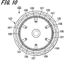
- FIGS. 9 and 10 are views showing a fourth embodiment of the storage case.
- FIG. 11 is a view showing a fourth embodiment of the injection needle unit.
- the difference between the injection needle unit 91 according to the fourth embodiment and the injection needle unit 1 according to the first embodiment is the configuration of the engaging portion and the engaged portion. Therefore, here, the engaging portion and the engaged portion will be described, and portions common to the injection needle assembly 2 and the storage case 8 are denoted by the same reference numerals, and redundant description is omitted.
- the storage case 101 of the injection needle unit 91 includes a hollow, substantially cylindrical case main body 102 that is open at one end in the axial direction and closed at the other end.
- the case main body 102 includes a substantially circular bottom surface portion 103 and a side surface portion 104 that extends substantially vertically from the bottom surface portion 103.
- a flange portion 105 that protrudes in a radially outward direction from the side surface portion 104 is provided at one end portion on the opening side of the case main body 102.
- Six first fitting receiving portions 106 indicating the engaged portions and six guide portions 107 are formed on the inner wall of the side surface portion 104.
- the six guide portions 107 are provided on the inner wall of the side surface portion 104 at intervals along the circumferential direction.
- the guide portion 107 bulges in a substantially triangular shape along the wall surface of the inner wall of the side surface portion 104. That is, the guide 107 has a tapered shape on the opening side of the case body 102.
- six first fitting receiving portions 106 are provided between the six guide portions 107.
- the first fitting receiving portion 106 is formed on the side of the bottom portion 103 in the axial direction of the case main body 102 in the guide portion 107.
- the number of the first fitting receiving units 106 and the guide units 107 is not limited to six, and may be five or less, or seven or more.
- a second fitting receiving portion 109 indicating an engaged portion is formed on the six rib pieces 108 erected at the corner portions of the bottom surface portion 103 and the side surface portion 104.
- the second fitting receiving portion 109 is provided on the end surface of the rib piece 108 opposite to the side surface portion 104.
- the needle hub 93 in the injection needle assembly 92 is provided with two first fitting portions 94 and second fitting portions 95 indicating the engaging portions.
- the two first fitting portions 94 protrude from the outer edge of the guide portion 98 in the radially outward direction.
- the number of the first fitting portions 94 is not limited to two, and only one first fitting portion 94 or three or more first fitting portions 94 may be provided.
- a second fitting portion 95 is provided on the side surface portion of the stabilizing portion 97.
- the second fitting portion 95 protrudes from the outer peripheral surface of the stabilizing portion 97 in the radially outward direction. Further, the second fitting portion 95 is formed continuously along the circumferential direction of the outer peripheral surface of the stabilizing portion 97.
- FIG. 12 and 13 are partial cross-sectional views showing a state in which the injection needle assembly 92 is stored in the storage case 101.
- FIG. 12A the stable portion 97 of the needle hub 93 is inserted into a space surrounded by six rib pieces 108 provided on the case main body 102. Then, as shown in FIG. 12 (b), the second fitting portion 95 provided on the outer peripheral surface of the stabilizing portion 97 is fitted to the second fitting receiving portion 109 provided on the rib piece 108.
- the first fitting portion 94 provided in the guide portion 98 in the needle hub 93 is first along the end surface 107 a of the guide portion 107 provided in the side surface portion 104 in the case main body 102. To the fitting receiving portion 106. Then, as shown in FIG. 13B, the first fitting portion 94 is fitted with the first fitting receiving portion 106. Accordingly, in the injection needle assembly 92, the first fitting portion 94 and the second fitting portion 95 are fitted with the first fitting receiving portion 106 and the second fitting receiving portion 109, respectively. Thus, the movement of the needle tube 5 in the axial direction is restricted.
- the first fitting portion 94 is disposed between the two guide portions 107 and comes into contact with the end surface 107 a of the guide portion 107. Thereby, the rotation of the needle tube 5 in the injection needle assembly 92 around the axial direction, that is, in the circumferential direction is restricted.
- the first fitting portion 94 is disengaged from the guide portion 107 and the first fitting receiving portion 106 when a predetermined load is applied in the circumferential direction, and gets over the end face 107a of the guide portion 107.
- the force (engagement force) when the first fitting portion 94 gets over the end surface 107a of the guide portion 107 is larger than the fastening force required when the syringe and the needle hub 93 are connected, and the screw portion of the syringe and the needle hub. It is set smaller than the load at which the thread portion and the thread groove are broken when the thread groove 93 is tightened.
- This engagement force is set to, for example, 5 to 50 cN ⁇ m, preferably 20 to 40 cN ⁇ m.
- the embodiments of the injection needle assembly, the storage case, the injection needle unit, and the drug injection device according to the present invention have been described above including the effects thereof.
- the injection needle assembly, the storage case, the injection needle unit, and the medicine injection device of the present invention are not limited to the above-described embodiments, and do not depart from the gist of the invention described in the claims. Various modifications are possible.
- the injection needle assembly may be configured without providing the elastic member.
- the second member and the elastic member may be integrally formed.
- the protrusions and / or knurls constituting the engaging portion and the engaged portion are formed in a right triangle shape, and the engaging portion and the engaged portion are disengaged by rotation in only one direction. May be. That is, the engagement portion and the engaged portion are disengaged only when a torque of a predetermined load or more is applied in the rotational direction in which the screw portion and the screw groove are tightened, and the engagement is not disengaged with the torque in the reverse direction. Like that. As a result, when the syringe needle assembly after drug administration is stored in the storage case, the syringe needle assembly does not rotate in the direction in which the screw portion and the screw groove are unfastened. Can be removed.
Landscapes
- Health & Medical Sciences (AREA)
- Vascular Medicine (AREA)
- Engineering & Computer Science (AREA)
- Anesthesiology (AREA)
- Biomedical Technology (AREA)
- Heart & Thoracic Surgery (AREA)
- Hematology (AREA)
- Life Sciences & Earth Sciences (AREA)
- Animal Behavior & Ethology (AREA)
- General Health & Medical Sciences (AREA)
- Public Health (AREA)
- Veterinary Medicine (AREA)
- Diabetes (AREA)
- Infusion, Injection, And Reservoir Apparatuses (AREA)
Abstract
La présente invention concerne une unité d'aiguille d'injection (4) qui comprend un canal d'aiguille (5), un pavillon d'aiguille (6), une partie de prise (25) et un étui de stockage (8). Le pavillon d'aiguille (8) renferme le canal d'aiguille (5) et a un sillon fileté (35) dans lequel se visse la partie vis (53) d'une seringue (3). La partie de prise (25) est dotée d'une partie avant latérale du pavillon d'aiguille (6). L'étui de stockage (8) comprend un corps principal d'étui tubulaire (61) qui accueille le pavillon d'aiguille (6) et une partie en prise (67) qui est fournie à l'intérieur du corps principal d'étui (61) et se met en prise avec la partie de prise (25). La partie de prise (25) et la partie en prise (67) sont libérées l'une de l'autre lorsqu'une charge prédéterminée est appliquée dans la direction axiale.
Applications Claiming Priority (2)
| Application Number | Priority Date | Filing Date | Title |
|---|---|---|---|
| JP2011-073178 | 2011-03-29 | ||
| JP2011073178 | 2011-03-29 |
Publications (1)
| Publication Number | Publication Date |
|---|---|
| WO2012132761A1 true WO2012132761A1 (fr) | 2012-10-04 |
Family
ID=46930508
Family Applications (1)
| Application Number | Title | Priority Date | Filing Date |
|---|---|---|---|
| PCT/JP2012/055362 Ceased WO2012132761A1 (fr) | 2011-03-29 | 2012-03-02 | Unité d'aiguille d'injection, étui de stockage, ensemble d'aiguille d'injection et dispositif d'injection de médicament |
Country Status (1)
| Country | Link |
|---|---|
| WO (1) | WO2012132761A1 (fr) |
Cited By (1)
| Publication number | Priority date | Publication date | Assignee | Title |
|---|---|---|---|---|
| WO2015075091A1 (fr) * | 2013-11-21 | 2015-05-28 | Sanofi-Aventis Deutschland Gmbh | Emballage de raccord de cartouche |
Citations (3)
| Publication number | Priority date | Publication date | Assignee | Title |
|---|---|---|---|---|
| JP2004532677A (ja) * | 2001-04-13 | 2004-10-28 | ベクトン・ディキンソン・アンド・カンパニー | 皮内針 |
| JP2009101140A (ja) * | 2007-09-07 | 2009-05-14 | Becton Dickinson & Co | ペン用針を過小におよび過大に回転させることを防止するためのペン型針アセンブリ |
| JP2010172603A (ja) * | 2009-01-30 | 2010-08-12 | Terumo Corp | 注射針組立体および薬剤注射装置 |
-
2012
- 2012-03-02 WO PCT/JP2012/055362 patent/WO2012132761A1/fr not_active Ceased
Patent Citations (3)
| Publication number | Priority date | Publication date | Assignee | Title |
|---|---|---|---|---|
| JP2004532677A (ja) * | 2001-04-13 | 2004-10-28 | ベクトン・ディキンソン・アンド・カンパニー | 皮内針 |
| JP2009101140A (ja) * | 2007-09-07 | 2009-05-14 | Becton Dickinson & Co | ペン用針を過小におよび過大に回転させることを防止するためのペン型針アセンブリ |
| JP2010172603A (ja) * | 2009-01-30 | 2010-08-12 | Terumo Corp | 注射針組立体および薬剤注射装置 |
Cited By (1)
| Publication number | Priority date | Publication date | Assignee | Title |
|---|---|---|---|---|
| WO2015075091A1 (fr) * | 2013-11-21 | 2015-05-28 | Sanofi-Aventis Deutschland Gmbh | Emballage de raccord de cartouche |
Similar Documents
| Publication | Publication Date | Title |
|---|---|---|
| JP5604438B2 (ja) | 注射針組立体および薬剤注射装置 | |
| JP6284595B2 (ja) | 注射針組立体及び薬剤注射装置 | |
| JP6636503B2 (ja) | 注射針組立体および薬剤注射装置 | |
| JP5726741B2 (ja) | 注射針組立体および薬剤注射装置 | |
| JP5719522B2 (ja) | 薬剤投与器具及び薬剤注射装置 | |
| JP5667571B2 (ja) | 注射針組立体及び薬剤注射装置 | |
| JP5756793B2 (ja) | 注射針組立体及び薬剤注射装置 | |
| JP5894582B2 (ja) | 注射針組立体及び薬剤注射装置 | |
| JP6605585B2 (ja) | 薬剤注射装置 | |
| JP5955838B2 (ja) | 注射針組立体及び薬剤注射装置 | |
| CN107427647A (zh) | 注射针组装体及药剂注射装置 | |
| WO2011040222A1 (fr) | Ensemble aiguille hypodermique et dispositif d'injection de médicament | |
| WO2012160852A1 (fr) | Ensemble aiguille d'injection et dispositif d'injection de médicament | |
| WO2012132761A1 (fr) | Unité d'aiguille d'injection, étui de stockage, ensemble d'aiguille d'injection et dispositif d'injection de médicament | |
| JP5432272B2 (ja) | 注射補助具及び薬剤注射装置 | |
| WO2012157313A1 (fr) | Unité aiguille d'injection | |
| WO2012157318A1 (fr) | Ensemble d'aiguille d'injection et dispositif d'injection de médicament | |
| WO2012157312A1 (fr) | Unité aiguille d'injection | |
| JP5270424B2 (ja) | 薬剤注射装置および注射針組立体 | |
| JP6681331B2 (ja) | 注射針組立体、薬剤注射装置 | |
| CN107427648A (zh) | 注射针组装体及药剂注射装置 |
Legal Events
| Date | Code | Title | Description |
|---|---|---|---|
| 121 | Ep: the epo has been informed by wipo that ep was designated in this application |
Ref document number: 12764163 Country of ref document: EP Kind code of ref document: A1 |
|
| NENP | Non-entry into the national phase |
Ref country code: DE |
|
| 122 | Ep: pct application non-entry in european phase |
Ref document number: 12764163 Country of ref document: EP Kind code of ref document: A1 |
|
| NENP | Non-entry into the national phase |
Ref country code: JP |