WO2012132929A1 - Dispositif récepteur d'énergie comportant un panneau tactile et système de transmission d'énergie destiné à alimenter en énergie un dispositif récepteur d'énergie - Google Patents
Dispositif récepteur d'énergie comportant un panneau tactile et système de transmission d'énergie destiné à alimenter en énergie un dispositif récepteur d'énergie Download PDFInfo
- Publication number
- WO2012132929A1 WO2012132929A1 PCT/JP2012/056692 JP2012056692W WO2012132929A1 WO 2012132929 A1 WO2012132929 A1 WO 2012132929A1 JP 2012056692 W JP2012056692 W JP 2012056692W WO 2012132929 A1 WO2012132929 A1 WO 2012132929A1
- Authority
- WO
- WIPO (PCT)
- Prior art keywords
- power
- power receiving
- receiving device
- electrode
- power transmission
- Prior art date
- Legal status (The legal status is an assumption and is not a legal conclusion. Google has not performed a legal analysis and makes no representation as to the accuracy of the status listed.)
- Ceased
Links
Images





Classifications
-
- H—ELECTRICITY
- H02—GENERATION; CONVERSION OR DISTRIBUTION OF ELECTRIC POWER
- H02J—ELECTRIC POWER NETWORKS; CIRCUIT ARRANGEMENTS OR SYSTEMS FOR SUPPLYING OR DISTRIBUTING ELECTRIC POWER; SYSTEMS FOR STORING ELECTRIC ENERGY
- H02J50/00—Circuit arrangements or systems for wireless supply or distribution of electric power
- H02J50/05—Circuit arrangements or systems for wireless supply or distribution of electric power using capacitive coupling
-
- G—PHYSICS
- G06—COMPUTING OR CALCULATING; COUNTING
- G06F—ELECTRIC DIGITAL DATA PROCESSING
- G06F1/00—Details not covered by groups G06F3/00 - G06F13/00 and G06F21/00
- G06F1/16—Constructional details or arrangements
- G06F1/1613—Constructional details or arrangements for portable computers
- G06F1/1626—Constructional details or arrangements for portable computers with a single-body enclosure integrating a flat display, e.g. Personal Digital Assistants [PDAs]
-
- G—PHYSICS
- G06—COMPUTING OR CALCULATING; COUNTING
- G06F—ELECTRIC DIGITAL DATA PROCESSING
- G06F1/00—Details not covered by groups G06F3/00 - G06F13/00 and G06F21/00
- G06F1/16—Constructional details or arrangements
- G06F1/1613—Constructional details or arrangements for portable computers
- G06F1/1632—External expansion units, e.g. docking stations
-
- G—PHYSICS
- G06—COMPUTING OR CALCULATING; COUNTING
- G06F—ELECTRIC DIGITAL DATA PROCESSING
- G06F1/00—Details not covered by groups G06F3/00 - G06F13/00 and G06F21/00
- G06F1/16—Constructional details or arrangements
- G06F1/1613—Constructional details or arrangements for portable computers
- G06F1/1633—Constructional details or arrangements of portable computers not specific to the type of enclosures covered by groups G06F1/1615 - G06F1/1626
- G06F1/1637—Details related to the display arrangement, including those related to the mounting of the display in the housing
- G06F1/1643—Details related to the display arrangement, including those related to the mounting of the display in the housing the display being associated to a digitizer, e.g. laptops that can be used as penpads
-
- G—PHYSICS
- G06—COMPUTING OR CALCULATING; COUNTING
- G06F—ELECTRIC DIGITAL DATA PROCESSING
- G06F1/00—Details not covered by groups G06F3/00 - G06F13/00 and G06F21/00
- G06F1/26—Power supply means, e.g. regulation thereof
-
- H—ELECTRICITY
- H02—GENERATION; CONVERSION OR DISTRIBUTION OF ELECTRIC POWER
- H02J—ELECTRIC POWER NETWORKS; CIRCUIT ARRANGEMENTS OR SYSTEMS FOR SUPPLYING OR DISTRIBUTING ELECTRIC POWER; SYSTEMS FOR STORING ELECTRIC ENERGY
- H02J50/00—Circuit arrangements or systems for wireless supply or distribution of electric power
- H02J50/90—Circuit arrangements or systems for wireless supply or distribution of electric power involving detection or optimisation of position, e.g. alignment
-
- H—ELECTRICITY
- H04—ELECTRIC COMMUNICATION TECHNIQUE
- H04B—TRANSMISSION
- H04B5/00—Near-field transmission systems, e.g. inductive or capacitive transmission systems
- H04B5/20—Near-field transmission systems, e.g. inductive or capacitive transmission systems characterised by the transmission technique; characterised by the transmission medium
- H04B5/22—Capacitive coupling
-
- H—ELECTRICITY
- H04—ELECTRIC COMMUNICATION TECHNIQUE
- H04M—TELEPHONIC COMMUNICATION
- H04M1/00—Substation equipment, e.g. for use by subscribers
- H04M1/02—Constructional features of telephone sets
-
- H—ELECTRICITY
- H02—GENERATION; CONVERSION OR DISTRIBUTION OF ELECTRIC POWER
- H02J—ELECTRIC POWER NETWORKS; CIRCUIT ARRANGEMENTS OR SYSTEMS FOR SUPPLYING OR DISTRIBUTING ELECTRIC POWER; SYSTEMS FOR STORING ELECTRIC ENERGY
- H02J7/00—Circuit arrangements for charging or discharging batteries or for supplying loads from batteries
- H02J7/70—Circuit arrangements for charging or discharging batteries or for supplying loads from batteries characterised by the mechanical construction
-
- H—ELECTRICITY
- H04—ELECTRIC COMMUNICATION TECHNIQUE
- H04M—TELEPHONIC COMMUNICATION
- H04M2250/00—Details of telephonic subscriber devices
- H04M2250/22—Details of telephonic subscriber devices including a touch pad, a touch sensor or a touch detector
Definitions
- the present invention relates to a power receiving device having a touch panel and a power transmission system that supplies power to the power receiving device, and more particularly to a wireless power transmission system that supplies power to the power receiving device in a contactless manner.
- a power receiving device having a conventional touch panel there are various electronic devices, and there are many various electronic devices such as a mobile phone, a portable game machine, a digital camera, a personal digital assistant (PDA), a digital audio device, and a digital information device. Used in the direction.
- a touch panel provided with a touch sensor made of a transparent electrode film on a display such as a liquid crystal display panel has been adopted in many electronic devices (see Patent Document 1). Since these power receiving devices are portable, they hold a secondary battery that is a storage battery and are driven by electric power output from the secondary battery.
- the electric field coupling method is a method of transmitting electric power from the power supply circuit on the power transmission side to the secondary battery circuit on the power reception side in a state where the electrodes on the power transmission side and the power reception side are close to each other and are electric field coupled (capacitive coupling).
- a portable power receiving device having a touch panel as described above it is an important issue to supply power efficiently and in a short time to a secondary battery as a storage battery. Is also an important issue to be solved. Furthermore, in recent years, portable power receiving devices have been further reduced in size, weight, and thickness, and this trend is thought to further accelerate. As a result, the arrangement space of each component in the power receiving device is limited, and it is necessary to miniaturize each component, and simplification of the configuration of the power receiving device is an important issue to be solved. Furthermore, it is an important problem to be solved together with providing the power receiving device as described above to construct a power transmission system for easily and efficiently supplying power to such a power receiving device.
- the power receiving device is provided on a display panel, and the movable transparent electrode film and the fixed transparent electrode film are opposed to each other.
- a touch panel that functions as a resistive touch sensor,
- a position detection circuit for detecting an indicated position (operation position) on the touch panel;
- a power receiving circuit that supplies electric power received by the movable transparent electrode to a secondary battery as a power receiving antenna of an electric field coupling method, and control for selectively switching and controlling to drive one of the power receiving circuit and the position detection circuit Part.
- the movable transparent electrode film in the touch sensor having a large area that is substantially exposed as an appearance is used as a power receiving antenna (power receiving electrode) of an electric field coupling method. Therefore, power reception efficiency is high, and power can be supplied in a short time.
- the movable transparent electrode film in the touch sensor is used as a part of the power receiving mechanism and the movable transparent electrode film has a dual structure, the number of parts can be reduced, and the apparatus can be reduced in weight and thickness.
- the power receiving device switches from the position detection circuit to the power receiving circuit when the control unit according to the first aspect is in a power transferable state in the movable transparent electrode film. It is configured to control and supply power to the secondary battery via the movable transparent electrode.
- the power receiving device of the second aspect configured as described above can execute the power feeding operation by a simple operation.
- the power receiving device is configured such that the movable transparent electrode film according to the first aspect functions as a passive electrode in an electric field coupling method.
- the power receiving device of the third aspect configured as described above can be reduced in size, weight, and thickness, and can perform a highly efficient power feeding operation.
- the touch panel according to the first aspect is divided into at least two parts, and the movable transparent electrode film constituting the touch panel is used as a passive electrode and an active electrode in an electric field coupling method. Configured to work.
- the power receiving device of the fourth aspect configured as described above can be reduced in size, weight, and thickness, and can perform a power feeding operation with high efficiency.
- the movable transparent electrode film in the first aspect functions as a passive electrode in the electric field coupling method, and the active electrode in the electric field coupling method is flush with the passive electrode. It is juxtaposed above.
- the power receiving device of the fifth aspect configured as described above can be reduced in size, weight, and thickness, and can be supplied with high efficiency.
- the power receiving device of the sixth aspect according to the present invention is a surface in which the movable transparent electrode film in the first aspect functions as a passive electrode in the electric field coupling method, and the active electrode in the electric field coupling method is different from the passive electrode. Is placed on top.
- the power receiving device of the sixth aspect configured as described above has a configuration in which the degree of freedom in design increases and power can be supplied efficiently.
- the touch panel according to the first aspect includes a plurality of touch panel constituent parts, and the movable transparent electrode constituent part in at least one touch panel constituent part is passive in an electric field coupling method.
- the control unit performs switching control from the position detection circuit to the power receiving circuit, and the second unit through the movable transparent electrode constituent unit. It is configured to supply power to the secondary battery.
- the power receiving device according to the seventh aspect configured as described above can execute the power feeding operation with a simple operation.
- the power receiving device is the power receiving device according to the seventh aspect, wherein the control unit switches to the power receiving circuit and is in a power feeding state with respect to the secondary battery. It is configured to function as a touch sensor for a touch panel.
- the power receiving device of the eighth aspect configured as described above can perform a power feeding operation with a simple operation, and can use a touch sensor even in a power feeding state, and has excellent operability. This makes it a convenient power receiving device.
- a power transmission system includes a secondary battery, and a movable transparent electrode film and a fixed transparent electrode film are disposed on the display panel so as to function as a resistive film type touch sensor.
- a power receiving device with a touch panel And a power transmission device having a power transmission electrode on which the power reception device is mounted and transmitting electric power by an electric field coupling method using the movable transparent electrode film as a power reception electrode.
- the power transmission system according to the ninth aspect configured as described above can easily and efficiently supply power from the power transmitting device to the power receiving device.
- the movable transparent electrode film of the power receiving device functions as a passive electrode in an electric field coupling method
- the movable transparent electrode film is the power transmission system. Power transmission is performed when at least a part of the device faces a passive electrode as a power transmission electrode of the device.
- the power transmission system according to the tenth aspect configured as described above can perform the power transmission / reception operation with a simple operation.
- the touch panel of the power receiving device is divided into at least two parts, and the movable transparent electrode film constituting the touch panel is an electric field coupling method. It functions as a passive electrode and an active electrode, and the movable transparent electrode film is configured to execute power transmission when at least a part of each of the movable electrode and the passive electrode as the power transmission electrode of the power transmission device faces each other. .
- the power transmission system according to the eleventh aspect thus configured can be reduced in size, weight, and thickness in the power receiving device, and a highly efficient wireless power transmission system can be constructed.
- a power transmission system is the power receiving device according to the ninth aspect, wherein the movable transparent electrode film functions as a passive electrode in an electric field coupling method, Passive electrodes are juxtaposed on the same surface, In the power transmission device, the active electrode and the passive electrode in the electric field coupling method are arranged side by side on the same plane, In a power feeding state by an electric field coupling method from the power transmitting device to the power receiving device, at least a part of each active electrode and passive electrode is arranged to face each other.
- the power transmission system according to the twelfth aspect thus configured can be reduced in size, weight and thickness in the power receiving device, and a highly efficient wireless power transmission system can be constructed.
- the movable transparent electrode film functions as a passive electrode in the electric field coupling method, Passive electrodes are placed on different surfaces, In the power transmission device, the active electrode and the passive electrode in the electric field coupling method are arranged on different planes, In a power feeding state by an electric field coupling method from the power transmitting device to the power receiving device, at least a part of each active electrode and passive electrode is arranged to face each other.
- the power transmission system according to the thirteenth aspect configured as described above has a configuration in which the degree of freedom in design of the power receiving device increases and power can be supplied with high efficiency.
- a power transmission system is the power receiving device according to the ninth aspect, wherein the touch panel has a plurality of touch panel components, and the movable transparent electrode component in at least one touch panel component. Functions as a passive electrode in the electric field coupling method, In the power transmission device, a passive electrode as a power transmission electrode that is movable to a position facing the passive electrode of the power receiving device is provided.
- the power transmission system according to the fourteenth aspect configured as described above can perform the power transmission / reception operation with a simple operation.
- the power transmission device sandwiches the power reception device such that the passive electrode of the power transmission device of the fourteenth aspect faces the passive electrode of the power reception device. It is configured.
- the power transmission system according to the fifteenth aspect configured as described above can reliably perform the power transmission / reception operation with a simple operation.
- the power transmission system according to the sixteenth aspect of the present invention is configured such that at least one movable transparent electrode component functions as a touch sensor of a touch panel in the power feeding state of the fourteenth power receiving device.
- the power transmission system according to the sixteenth aspect configured as described above can perform the power transmission / reception operation with a simple operation and can use the function of the touch sensor in the power supply state.
- the present invention it is possible to provide a power receiving device having high power receiving efficiency and capable of supplying power in a short time, and the power receiving device can be reduced in size, weight and thickness, and can perform power transmission and reception operations. It is possible to provide a power transmission system that can be efficiently performed with a simple operation.
- FIG. 1 The top view which shows the power receiving device and power transmission device which are used for the power transmission system of Embodiment 1 which concerns on this invention.
- Sectional drawing which shows the touchscreen on the liquid crystal display panel of the power receiving device in Embodiment 1 Schematic diagram illustrating a power transmission system according to Embodiment 1
- the top view which showed the electric power feeding state which mounted the power receiving device on the power transmission device in the power transmission system of Embodiment 1.
- the top view which showed the electric power feeding state which mounted the power receiving device on the power transmission device The side view which shows the state which mounted the power receiving device on the power transmission device in the power transmission system of Embodiment 3.
- Configuration diagram for explaining a power transmission system according to a third embodiment
- the perspective view which shows the modification of the shape of the touchscreen of the power receiving device used for the power transmission system of this invention.
- the perspective view which shows another modification of the shape of the touchscreen of the power receiving device used for the power transmission system of this invention.
- a PDA Personal Data Assistant
- a mobile phone function as a portable power receiving device having a touch panel and a power transmission system for supplying power to the PDA
- the invention is not limited to the configuration specifically described in the following embodiment, and is configured based on the technical idea similar to the technical idea described in the embodiment and the common general technical knowledge in this technical field.
- the present invention is applied to various electronic devices and a power transmission system that supplies power to these electronic devices. Note that, in the power transmission system according to the present invention, a form in which power is supplied to the power receiving device by an electric field coupling (capacitive coupling) method is used.
- FIG. 1 is a plan view showing a power receiving device 1 used in the power transmission system according to the first embodiment of the present invention and a power transmitting device 2 that feeds (charges) power to the power receiving device 1.
- a power receiving device 1 is a PDA having a mobile phone function, and a touch panel 3 serving as an operation surface is provided on a substantially entire surface.
- the power receiving device 1 is a device to be charged and has a secondary battery (not shown).
- a power transmission device 2 that wirelessly feeds power (wireless power transmission) to the secondary battery of the power receiving device 1 is provided.
- the power receiving device 1 is placed on the power transmitting device 2, and wireless power transmission to the power receiving device 1 is performed by an electric field coupling method.
- the electrode provided in the power receiving device 1 and the electrode provided in the power transmission device 2 need to be arranged in close proximity to each other to be in a capacitive coupling state. .
- the touch panel 3 is provided on the surface of the power receiving device 1, the transparent electrode of the touch panel 3 is used as a power receiving antenna for wireless power transmission.
- Embodiment 1 the use of the transparent electrode of the touch panel 3 as a power receiving antenna, that is, a power receiving electrode will be described.
- a power receiving configuration in the power receiving device 1 that is a device to be charged in the power transmission system of the first embodiment will be described.
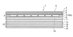
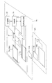
- FIG. 2 is a cross-sectional view showing the touch panel 3 on the liquid crystal display panel in the power receiving device 1.
- the touch panel 3 includes a hard coat layer 4, a movable side film 5, a shrinkable resin film 6, a movable transparent electrode film 7, a fixed transparent electrode film 10, and a fixed side support in order from the surface side (upper side in FIG. 2). 11 is provided, and a spacer 9 is disposed between the movable transparent electrode film 7 and the fixed transparent electrode film 10.
- the movable film 5, the movable transparent electrode film 7, the fixed transparent electrode film 10, and the fixed support 11 are bonded and bonded together at the peripheral portion by the peripheral adhesive layer 8.
- the movable transparent electrode film 7 is made of metal such as gold, silver, copper, tin, nickel, and palladium, or metal oxide such as tin oxide, indium oxide, antimony oxide, zinc oxide, cadmium oxide, and indium tin oxide (ITO).
- the transparent conductive film is used.
- a vacuum deposition method, a sputtering method, an ion plating method, a CVD method, or the like is used as a method for forming the movable transparent electrode film 7, a vacuum deposition method, a sputtering method, an ion plating method, a CVD method, or the like is used.
- the fixed transparent electrode film 10 is formed on the upper surface of the fixed side support 11 made of a transparent film or transparent glass, and a transparent conductive film such as ITO is used in the same manner as the movable transparent electrode film 7 described above.
- the spacer 9 is used to maintain a gap between the movable transparent electrode film 7 and the fixed transparent electrode film 10, and a plurality of fine dots are formed by a photo process using a transparent resin such as photosensitive acrylic or photosensitive polyester. Configured. As the spacer 9, a plurality of fine dots formed by a printing method may be used.
- a display panel 12 is provided under the touch panel 3 configured as described above via a gap.
- the display panel 12 in the first embodiment is a liquid crystal display panel, and includes a deflection plate 13, a color filter substrate 14, a TFT substrate 15, and a deflection plate 16.
- the control unit 20 when the user performs a contact operation (instruction operation) on the display surface of the touch panel 3 that is the operation surface of the power receiving device 1, a voltage signal corresponding to the contact position is generated.
- the position detection signal is output to the control unit 20 (described later).
- the movable transparent electrode film 7 of the touch panel 3 functions as an electric field coupling type power receiving antenna (power receiving electrode).
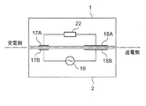
- FIG. 3 is a schematic diagram illustrating the power transmission system according to the first embodiment.
- the power receiving device 1 is provided with a power receiving side active electrode 17A and a power receiving side passive electrode 18A.
- the power transmission device 2 is provided with a power transmission side active electrode 17B and a power transmission side passive electrode 18B.
- the power receiving side active electrode 17A and the power transmitting side active electrode 17B, and the power receiving side passive electrode 18A and the power transmitting side passive electrode 18B are arranged to face each other. And is in a capacitively coupled state.
- the movable transparent electrode film 7 of the power receiving device 1 according to the first embodiment is used as the power receiving side passive electrode 18A. Since the power receiving device 1 in the first embodiment is configured so that the touch panel 3 is exposed, the touch panel 3 can be disposed at a position close to the power transmitting device 2.
- FIG. 4A is a plan view showing a state where the power receiving device 1 (one-dot chain line) is placed on the power transmitting device 2 (solid line), and shows a power feeding state.
- FIG. 4B is a side view showing a power feeding state in which the power receiving device 1 is placed on the power transmitting device 2. As shown in FIG. 4A and FIG. 4B, in the power feeding state, the active electrode 17A (the two-dot chain line in FIG. 4A) and the passive electrode 18A (the two-dot chain line in FIG.
- the passive electrode 18A of the power receiving device 1 that is, as the power receiving antenna, the possible transparent electrode film 7 of the touch panel 3 functioning as a touch sensor (position sensor) is used.
- the power receiving device 1 includes an active electrode 17A and a passive electrode 18A arranged in parallel on the same plane. Further, also in the power transmission device 2, the active electrode 17B and the passive electrode 18B are arranged in parallel on the same plane.
- the active electrodes 17A and 17B and the passive electrodes 18A and 18B in the power receiving device 1 and the power transmitting device 2 have been described as a configuration example having a planar shape, but the present invention is limited to this configuration example. It is not a thing.
- at least a part of the active electrode and the passive electrode may have a curved surface shape, as long as at least a part of each of the active electrode and the passive electrode is opposed to each other and can transmit power.
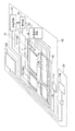
- FIG. 5 is a configuration diagram illustrating the power transmission system according to the first embodiment.
- FIG. 5 only the movable transparent electrode film 7 and the fixed transparent electrode film 10 of the touch panel 3 in the power receiving device 1 are illustrated as elements of the touch sensor.
- a control unit 20 including a switching unit 21, a power receiving circuit 22, and a position detection circuit 23 are provided as components related to the power transmission system.
- other elements necessary for the function of the power receiving device 1 for example, various elements necessary for the function of the liquid crystal display panel and the PDA are omitted.
- the control unit 20 of the power receiving device 1 detects that the power receiving device 1 is placed on the power transmitting device 2 and is in a power transferable state, the control unit 20 By performing this switching operation, the movable transparent electrode film 7 of the touch panel 3 is switched to the power receiving side passive electrode 18A so as to function as a power receiving antenna. As a result, the power receiving device 1 is supplied with power from the power transmitting device 2 by the electric field coupling method, and the secondary battery of the power receiving circuit 22 is charged.
- control unit 20 is in a power transferable state when at least a part of each active electrode and passive electrode is opposed to each other in a state where the power receiving device 1 is placed on the power transmission device 2 (power feeding state).
- the power supply operation is performed by performing the switching operation.
- the control unit 20 detects the state, and the switching unit 21 Thus, the movable transparent electrode film 7 is switched so as to function as a touch sensor (position sensor).
- Embodiment 1 the example in which the passive electrode 18A of the power receiving device 1 is configured by the movable transparent electrode film 7 of the touch panel 3 has been described.
- the present invention is not limited to the configuration as described above. It is also possible to divide the touch panel into a plurality of parts so that both the passive electrode and the active electrode function by two movable transparent electrode films.
- the power receiving device 1 of the first embodiment configured as described above is substantially exposed as an appearance, and the movable transparent electrode film 7 of the touch sensor having a large area is used as a power receiving antenna of an electric field coupling method. For this reason, by using the power transmission system of the first embodiment, the power receiving device 1 can supply power in a short time with high power receiving efficiency, and the movable transparent electrode film 7 of the touch sensor is also used as a power receiving antenna. Therefore, it is possible to reduce the number of parts and reduce the weight and thickness of the device.
- power can be efficiently supplied in a short time to the power receiving device 1 that is a device to be charged, and a simple operation can be performed. It can comprise so that it may be in an electric power feeding state by operation. Further, according to the configuration of the first embodiment, it is possible to easily achieve downsizing, weight reduction, and thickness reduction, which are important issues in a portable power receiving device.
- Embodiment 2 a PDA as a portable power receiving device according to a second embodiment of the present invention and a power transmission system for supplying power to the power receiving device will be described with reference to the accompanying drawings. Also in the power transmission system of the second embodiment, power is supplied from the power transmitting device to the power receiving device by the electric field coupling method.
- the difference from the configuration of the first embodiment described above is the arrangement of the active electrode and the passive electrode serving as the power receiving antenna and the power transmitting antenna, and the position of the touch panel of the power receiving device,
- the display panel under the touch panel is made of an electromagnetically permeable material.
- Other configurations of the power receiving device and the power transmission system of the second embodiment are the same as those of the first embodiment. Therefore, in Embodiment 2, the same code
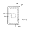
- FIG. 6A is a plan view showing a state where the power receiving device 1A (one-dot chain line) is placed on the power transmitting device 2A (solid line), and shows a power feeding state.
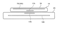
- FIG. 6B is a side view showing a power feeding state in which the power receiving device 1A is placed on the power transmitting device 2A.
- the power receiving device 2 in the power supply state in which the power receiving device 1A of Embodiment 2 is placed on the power transmitting device 2A, the touch panel 3A of the power receiving device 1A is exposed upward so that it can be seen. Arranged to do. Therefore, the power receiving device 2 according to the second embodiment has a configuration in which the image display on the display panel can be confirmed even in the power supply state.
- the power receiving device 1A When power is supplied from the power transmitting device 2A to the power receiving device 1A in the power transmission system of the second embodiment, the power receiving device 1A is placed on the power transmitting device 2A, and the active electrode 17A of the power receiving device 1A (two-dot chain line in FIG. 6A). Is disposed in opposition to and close to the active electrode 17B of the power transmission device 2A (substantially square electrode indicated by a broken line in FIG. 6A). In this power supply state, the touch panel 3A of the power receiving device 1A is in an exposed state, but the movable transparent electrode film 7A of the touch panel 3A that is the passive electrode 18A of the power receiving device 1A (a substantially rectangular electrode indicated by a two-dot chain line in FIG. 6A). Is disposed at a position facing the passive electrode 18B of the power transmission device 2A (a substantially rectangular electrode indicated by a broken line in FIG. 6A).
- the active electrode 17A and the passive electrode 18A are formed to overlap each other, and the respective electrodes 17A and 18A are disposed in the central region of the power receiving device 1A.
- the active electrode 17B and the passive electrode 18B of the power transmission device 2A are formed to overlap each other, and the respective electrodes 17B and 18B are disposed in the central region of the power transmission device 2A.
- the active electrode 17A and the passive electrode 18A are arranged on different planes as shown in FIG. 6B. Also in the power transmission device 2A, the active electrode 17B and the passive electrode 18B are arranged on different planes.
- the active electrodes 17A and 17B and the passive electrodes 18A and 18B in the power receiving device 1A and the power transmitting device 2A will be described as a configuration example having a planar shape, but the present invention is limited to this configuration example. It is not a thing.
- at least a part of the active electrode and the passive electrode may have a curved surface shape, as long as at least a part of each of the active electrode and the passive electrode is opposed to each other and can transmit power.
- FIG. 7 is a configuration diagram illustrating the power transmission system according to the second embodiment.
- FIG. 7 only the movable transparent electrode film 7A and the fixed transparent electrode film 10 of the touch panel 3A in the power receiving device 1A are illustrated as elements of the touch sensor.
- the basic configuration of the power receiving device 1A and the power transmitting device 2A is the same as that of the power receiving device 1 and the power transmitting device 2 of the first embodiment shown in FIG.
- a control unit 20 including a switching unit 21, a power receiving circuit 22, and a position detection circuit 23 are provided, and have the same configuration as in the first embodiment. The same applies to the operations in power transmission and position detection.
- the control unit 20 of the power receiving device 1 ⁇ / b> A detects that the power receiving device 1 ⁇ / b> A is placed on the power transmission device 2 ⁇ / b> A and enters the power transmission state, the control unit 20 performs the switching operation of the switching unit 21.
- the movable transparent electrode film 7A of the touch panel 3A is switched so as to function as a power receiving antenna. That is, the movable transparent electrode film 7A is switched to the power receiving side passive electrode 18A.
- the power receiving device 1A is efficiently supplied with the power from the power transmitting device 2A by the electric field coupling method, and the secondary battery of the power receiving circuit 22 is charged.
- the control unit 20 detects the state, and the switching unit 21 Thus, the movable transparent electrode film 7A is switched to function as a touch sensor (position sensor).
- the power receiving device 1A of the second embodiment configured as described above is substantially exposed as an appearance, and the movable transparent electrode film 7A in a touch sensor having a large area is used as a power receiving antenna of an electric field coupling method. For this reason, according to the power transmission system of the second embodiment, the power receiving device 1A can supply power in a short time with high power receiving efficiency. Further, according to the configuration of the second embodiment, since the movable transparent electrode film 7A of the touch sensor is also used as a power receiving antenna, the number of parts can be reduced, and the weight and thickness of the device can be reduced.
- the active electrodes 17A and 17B and the passive electrodes 18A and 18B of the power receiving device 1A and the power transmitting device 2A are respectively disposed in the central region. For this reason, in the second embodiment, if the central regions of the power receiving device 1A and the power transmitting device 2A are opposed to each other, the power transmission is possible. Can be powered.
- Embodiment 3 a PDA as a portable power receiving device according to a third embodiment of the present invention and a power transmission system for supplying power to the power receiving device will be described with reference to the accompanying drawings. Also in the power transmission system of the third embodiment, power is supplied from the power transmitting device to the power receiving device by the electric field coupling method.
- the difference between the power receiving device and the power transmission system of Embodiment 3 and the configuration in Embodiment 1 described above is the arrangement of the active electrode and the passive electrode serving as the power receiving antenna and the power transmitting antenna, and the position of the touch panel of the power receiving device and It is a configuration. Since other configurations of the power receiving device and the power transmission system of the third embodiment are the same as those of the first embodiment, the same reference numerals are given to the components having the same functions and operations as those of the first embodiment in the third embodiment. Then, those descriptions use the description in Embodiment 1.
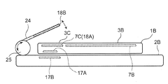
- FIG. 8A is a plan view showing a state where the power receiving device 1B (one-dot chain line) is placed on the power transmitting device 2B (solid line), and shows a power feeding state.
- FIG. 8B is a side view showing a state where the power receiving device 1B is placed on the power transmitting device 2B.
- the touch panel of the power receiving device 1B includes two touch panel components 3B and 3C.
- the first touch panel 3B is configured to function as a touch sensor (position sensor) in both the power supply state and the non-power supply state.
- the second touch panel component 3C functions as a power receiving antenna in the power supply state, functions as a touch sensor in the non-power supply state, and is configured to use both the power receiving antenna and the touch sensor.
- the first touch panel component 3B and the second touch panel component 3C in the third embodiment have the same configuration as the touch panel 3 described in the first embodiment, and have the same function. Accordingly, the first touch panel component 3B and the second touch panel component 3C have a predetermined gap between the movable transparent electrode component, which is a movable transparent electrode film, and the fixed transparent electrode component, which is a fixed transparent electrode film, respectively. And have a function as a touch sensor.
- each fixed transparent electrode constituent part in the first touch panel constituent part 3B and the second touch panel constituent part 3C is shown in the configuration example divided into two, but it is integrally formed as one constituent. Also good.
- the movable transparent electrode component in the second touch panel component 3C functions as a power receiving antenna (passive electrode) in addition to functioning as a touch sensor.
- the movable transparent electrode component 7C (18A) of the second touch panel component 3C is arranged so as to cover the component 3C and is configured to function as a passive electrode (power receiving antenna) on the power receiving side. Therefore, in the power receiving device 1B sandwiched by the power transmission unit 24 of the power transmission device 2B, the second touch panel configuration unit 3C and the passive electrode 18B of the power transmission unit 24 are disposed so as to face each other in close proximity (power transmission possible state) ).
- the power receiving device 1B according to the third embodiment in the power transmission enabled state, the first touch panel component 3B of the power receiving device 1B is arranged to face upward. Therefore, the power receiving device 1B according to the third embodiment has a configuration in which the first touch panel constituent unit 3B of the power receiving device 1B can be used as a touch sensor even in a power transfer enabled state.
- the passive electrode 18B of the power transmission unit 24 provided in the power transmission device 2B may be configured with a transparent electrode, and the power transmission unit 24 may be configured with a transparent body.
- the power transmission part 24 and the passive electrode 18B With a transparent material, it becomes a structure which can confirm the display image in 3 C of 2nd touchscreen structure parts also in an electric power feeding state.
- FIG. 9 is a configuration diagram illustrating the power transmission system according to the third embodiment.
- the movable transparent electrode components 7B and 7C and the fixed transparent electrode components 10B and 10C of the two touch panels 3B and 3C in the power receiving device 1B are illustrated as elements of the touch sensor.
- the fixed transparent electrode constituent portions 10B and 10C have been described as being divided. However, an integrated configuration may be used.
- the basic configuration of power receiving device 1B and power transmitting device 2B is the same as power receiving device 1 and power transmitting device 2 of the first embodiment shown in FIG.
- a control unit 20 including a switching unit 21, a power receiving circuit 22, and a position detection circuit 23 are provided, which are the same as those in the first embodiment. Each operation in position detection is the same.
- the movable transparent electrode constituent part 7C of the second touch panel constituent part 3C is used by switching the function as a touch sensor and the function as a power receiving antenna (passive electrode).
- the control unit 20 of the power receiving device 1B detects that the power receiving device 1B is placed on the power transmitting device 2B and is sandwiched by the power transmitting unit 24 and is in a power transferable state, the control is performed.
- the unit 20 performs a switching operation of the switching unit 21 and switches the movable transparent electrode configuration unit 7C of the second touch panel configuration unit 3C to function as a power receiving antenna. That is, the movable transparent electrode constituent part 7C of the second touch panel constituent part 3C is switched to the power receiving side passive electrode 18A.
- the power receiving device 1B reliably supplies the power from the power transmitting device 2B with high efficiency by the electric field coupling method, and the secondary battery of the power receiving circuit 22 is charged.
- the control unit 20 detects the state, and the switching unit 21
- the movable transparent electrode constituting unit 7C is switched to function as a touch sensor (position sensor).
- the movable transparent electrode constituent part 7C in the touch sensor substantially exposed as an appearance is used as a power receiving antenna of an electric field coupling method.
- the device 1B can easily supply power with high power receiving efficiency.
- the movable transparent electrode constituting unit 7C of the touch sensor also functions as the power receiving antenna, it is possible to reduce the number of parts and reduce the weight and thickness of the device. it can.
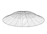
- FIG. 10A is perspective views showing two modifications as examples of the shape of the touch panel of the power receiving device used in the power transmission system of the present invention.
- the touch panel shown in FIG. 10A has a shape having a dome-shaped curved surface
- the touch panel shown in FIG. 10B has a shape in which both end regions are curved surfaces having a large curvature.
- a power transmission device including a touch panel having a curved surface as described above is used as a power transmission system, a power transmission device having a shape corresponding to the curved shape of the touch panel is provided, and the power transmission is possible in a state of facing each other. It is preferable to do.
- a touch panel having a curved surface shape the degree of freedom in the external design of the power receiving device is dramatically increased, and the design according to the user's request becomes possible.
- the present invention uses a touch panel used in various electronic devices such as a mobile phone, a portable game machine, a digital camera, a personal digital assistant (PDA), a digital audio device, and a digital information device as a power receiving antenna for wireless power transmission. It is used, has high versatility, and is useful in many portable electronic devices.
- PDA personal digital assistant
Landscapes
- Engineering & Computer Science (AREA)
- Theoretical Computer Science (AREA)
- Physics & Mathematics (AREA)
- General Engineering & Computer Science (AREA)
- General Physics & Mathematics (AREA)
- Computer Hardware Design (AREA)
- Human Computer Interaction (AREA)
- Computer Networks & Wireless Communication (AREA)
- Power Engineering (AREA)
- Signal Processing (AREA)
- Charge And Discharge Circuits For Batteries Or The Like (AREA)
- Position Input By Displaying (AREA)
Abstract
Priority Applications (3)
| Application Number | Priority Date | Filing Date | Title |
|---|---|---|---|
| KR1020137022880A KR20140036154A (ko) | 2011-03-30 | 2012-03-15 | 터치패널을 가진 수전 디바이스 및 수전 디바이스에 급전하는 전력 전송 시스템 |
| CN201280016716.XA CN103503276B (zh) | 2011-03-30 | 2012-03-15 | 具有触摸面板的受电设备及对受电设备供电的电力输送系统 |
| US14/007,503 US20140015337A1 (en) | 2011-03-30 | 2012-03-15 | Power receiving device having touch panel and power transmission system for feeding power to power receiving device |
Applications Claiming Priority (2)
| Application Number | Priority Date | Filing Date | Title |
|---|---|---|---|
| JP2011076323A JP5118226B2 (ja) | 2011-03-30 | 2011-03-30 | タッチパネルを有する受電デバイスおよび受電デバイスに給電する電力伝送システム |
| JP2011-076323 | 2011-03-30 |
Publications (1)
| Publication Number | Publication Date |
|---|---|
| WO2012132929A1 true WO2012132929A1 (fr) | 2012-10-04 |
Family
ID=46930664
Family Applications (1)
| Application Number | Title | Priority Date | Filing Date |
|---|---|---|---|
| PCT/JP2012/056692 Ceased WO2012132929A1 (fr) | 2011-03-30 | 2012-03-15 | Dispositif récepteur d'énergie comportant un panneau tactile et système de transmission d'énergie destiné à alimenter en énergie un dispositif récepteur d'énergie |
Country Status (5)
| Country | Link |
|---|---|
| US (1) | US20140015337A1 (fr) |
| JP (1) | JP5118226B2 (fr) |
| KR (1) | KR20140036154A (fr) |
| CN (1) | CN103503276B (fr) |
| WO (1) | WO2012132929A1 (fr) |
Cited By (3)
| Publication number | Priority date | Publication date | Assignee | Title |
|---|---|---|---|---|
| WO2014057798A1 (fr) * | 2012-10-12 | 2014-04-17 | 株式会社 東芝 | Réfrigérateur |
| CN103997075A (zh) * | 2013-02-15 | 2014-08-20 | 三星电子株式会社 | 显示设备和包括该显示设备的无线充电系统 |
| GB2522562A (en) * | 2012-10-17 | 2015-07-29 | Murata Manufacturing Co | Wireless power reception device, wireless power transmission device and wireless power transmission/reception device |
Families Citing this family (21)
| Publication number | Priority date | Publication date | Assignee | Title |
|---|---|---|---|---|
| WO2013051501A1 (fr) * | 2011-10-03 | 2013-04-11 | 株式会社村田製作所 | Système de transmission de puissance et dispositif transmetteur de puissance |
| WO2013168307A1 (fr) * | 2012-05-09 | 2013-11-14 | 株式会社村田製作所 | Système de transmission d'énergie sans fil |
| WO2014064975A1 (fr) * | 2012-10-26 | 2014-05-01 | 株式会社村田製作所 | Dispositif de réception de puissance sans fil, dispositif de transmission de puissance sans fil, et système de transmission de puissance sans fil |
| JP2014204348A (ja) * | 2013-04-05 | 2014-10-27 | 帝人株式会社 | アンテナ装置 |
| JP2014220889A (ja) * | 2013-05-07 | 2014-11-20 | 昭和電工株式会社 | ワイヤレス給電方法及びワイヤレス給電システム |
| CN105278724A (zh) * | 2014-07-25 | 2016-01-27 | 南京瀚宇彩欣科技有限责任公司 | 无挡触控的手持式电子装置、触控外盖及计算机执行的方法 |
| CN105320325A (zh) * | 2014-07-25 | 2016-02-10 | 南京瀚宇彩欣科技有限责任公司 | 无挡触控的手持式电子装置、触控外盖及计算机执行的方法 |
| CN105278723A (zh) * | 2014-07-25 | 2016-01-27 | 南京瀚宇彩欣科技有限责任公司 | 无挡触控的手持式电子装置、触控外盖及计算机执行方法 |
| CN105278851A (zh) * | 2014-07-25 | 2016-01-27 | 南京瀚宇彩欣科技有限责任公司 | 手持式电子装置、触控外盖及计算机执行的方法 |
| CN105302385A (zh) * | 2014-07-25 | 2016-02-03 | 南京瀚宇彩欣科技有限责任公司 | 无挡触控的手持式电子装置及其触控外盖 |
| CN104199576B (zh) | 2014-09-24 | 2018-03-27 | 联想(北京)有限公司 | 一种触摸屏、电子设备及无线充电方法 |
| TWI649689B (zh) * | 2015-02-13 | 2019-02-01 | 新益先創科技股份有限公司 | 電容影像感測系統 |
| EP3259675A4 (fr) * | 2015-02-19 | 2018-11-14 | Ossia Inc. | Antennes intégrées ou déposées en surface destinées à des installations énergétiques sans fil intégrées |
| KR101985127B1 (ko) | 2015-03-27 | 2019-05-31 | 후지필름 가부시키가이샤 | 터치 센서 및 터치 패널 |
| US10825417B2 (en) | 2015-04-10 | 2020-11-03 | Ossia Inc. | Wirelessly powered electronic display apparatuses |
| CN105656134B (zh) * | 2016-02-22 | 2019-06-07 | 京东方科技集团股份有限公司 | 屏幕以及包括该屏幕的设备 |
| AU2017318955B2 (en) | 2016-08-29 | 2020-06-25 | 3M Innovative Properties Company | Electronic hearing protector with switchable electrical contacts |
| KR102158204B1 (ko) | 2017-08-24 | 2020-09-22 | 동우 화인켐 주식회사 | 필름 안테나 및 이를 포함하는 디스플레이 장치 |
| TWI682638B (zh) * | 2017-09-29 | 2020-01-11 | 巨擘科技股份有限公司 | 腕錶及適用於腕錶之短距離通信信號強度的控制方法 |
| US20220224159A1 (en) * | 2019-04-26 | 2022-07-14 | Panasonic Intellectual Property Management Co., Ltd. | Wireless power and data transmission apparatus and transmission module |
| CN111245055B (zh) * | 2020-02-27 | 2022-05-20 | 维沃移动通信有限公司 | 一种电路控制装置及方法 |
Citations (3)
| Publication number | Priority date | Publication date | Assignee | Title |
|---|---|---|---|---|
| JPH11307376A (ja) * | 1998-04-20 | 1999-11-05 | Canon Inc | 非接触インターフェースおよびその電源供給方法 |
| JP2009148151A (ja) * | 2007-12-12 | 2009-07-02 | Lg Electronics Inc | 無線充電用メニュー提供機能を有する移動端末機及びその無線充電方法 |
| JP2010520741A (ja) * | 2007-03-05 | 2010-06-10 | ランダル ミッチ | 電子機器のための電気装置及び該電子機器への電力供給方法 |
-
2011
- 2011-03-30 JP JP2011076323A patent/JP5118226B2/ja not_active Expired - Fee Related
-
2012
- 2012-03-15 KR KR1020137022880A patent/KR20140036154A/ko not_active Withdrawn
- 2012-03-15 CN CN201280016716.XA patent/CN103503276B/zh not_active Expired - Fee Related
- 2012-03-15 US US14/007,503 patent/US20140015337A1/en not_active Abandoned
- 2012-03-15 WO PCT/JP2012/056692 patent/WO2012132929A1/fr not_active Ceased
Patent Citations (3)
| Publication number | Priority date | Publication date | Assignee | Title |
|---|---|---|---|---|
| JPH11307376A (ja) * | 1998-04-20 | 1999-11-05 | Canon Inc | 非接触インターフェースおよびその電源供給方法 |
| JP2010520741A (ja) * | 2007-03-05 | 2010-06-10 | ランダル ミッチ | 電子機器のための電気装置及び該電子機器への電力供給方法 |
| JP2009148151A (ja) * | 2007-12-12 | 2009-07-02 | Lg Electronics Inc | 無線充電用メニュー提供機能を有する移動端末機及びその無線充電方法 |
Cited By (11)
| Publication number | Priority date | Publication date | Assignee | Title |
|---|---|---|---|---|
| WO2014057798A1 (fr) * | 2012-10-12 | 2014-04-17 | 株式会社 東芝 | Réfrigérateur |
| JP2014199173A (ja) * | 2012-10-12 | 2014-10-23 | 株式会社東芝 | 冷蔵庫 |
| US10830524B2 (en) | 2012-10-12 | 2020-11-10 | Toshiba Lifestyle Products & Services Corporation | Refrigerator configured for interaction with portable information terminal |
| GB2522562A (en) * | 2012-10-17 | 2015-07-29 | Murata Manufacturing Co | Wireless power reception device, wireless power transmission device and wireless power transmission/reception device |
| US10033217B2 (en) | 2012-10-17 | 2018-07-24 | Murata Manufacturing Co., Ltd. | Wireless power receiver device, wireless power transmitter device, and wireless power transceiver device |
| CN103997075A (zh) * | 2013-02-15 | 2014-08-20 | 三星电子株式会社 | 显示设备和包括该显示设备的无线充电系统 |
| EP2767972A1 (fr) * | 2013-02-15 | 2014-08-20 | Samsung Electronics Co., Ltd | Dispositifs d'affichage, système de charge sans fil comprenant des dispositifs d'affichage et procédés permettant de faire fonctionner lesdits dispositifs |
| KR20140102987A (ko) * | 2013-02-15 | 2014-08-25 | 삼성전자주식회사 | 디스플레이 장치 및 이를 포함한 무선 충전 시스템 |
| US9711992B2 (en) | 2013-02-15 | 2017-07-18 | Samsung Electronics Co., Ltd. | Display devices, wireless charging system including display devices, and methods of operating the display devices |
| CN103997075B (zh) * | 2013-02-15 | 2018-03-13 | 三星电子株式会社 | 显示设备和包括该显示设备的无线充电系统 |
| KR102113258B1 (ko) * | 2013-02-15 | 2020-05-20 | 삼성전자주식회사 | 디스플레이 장치 및 이를 포함한 무선 충전 시스템 |
Also Published As
| Publication number | Publication date |
|---|---|
| US20140015337A1 (en) | 2014-01-16 |
| CN103503276B (zh) | 2014-12-17 |
| JP5118226B2 (ja) | 2013-01-16 |
| JP2012213251A (ja) | 2012-11-01 |
| KR20140036154A (ko) | 2014-03-25 |
| CN103503276A (zh) | 2014-01-08 |
Similar Documents
| Publication | Publication Date | Title |
|---|---|---|
| JP5118226B2 (ja) | タッチパネルを有する受電デバイスおよび受電デバイスに給電する電力伝送システム | |
| KR102262991B1 (ko) | 슬라이드 아웃 디스플레이를 포함하는 전자 장치 | |
| CN110851009B (zh) | 显示装置 | |
| EP2673944B1 (fr) | Dispositifs électroniques ayant des dispositifs d'affichage souples | |
| US9888599B2 (en) | Protecting cover for electronic device | |
| US20230395054A1 (en) | Vibration generating device and display apparatus including the same | |
| JP5352009B2 (ja) | 入力装置、表示装置、および機器 | |
| US9246213B2 (en) | Electronic device | |
| EP4645595A2 (fr) | Dispositif électronique comprenant un couvercle de protection pour protéger un affichage flexible | |
| US20110205173A1 (en) | Input device and electronic apparatus | |
| KR20100035059A (ko) | 이동 단말기 | |
| CN110851008A (zh) | 显示装置和制造该显示装置的方法 | |
| CN110837310A (zh) | 显示装置 | |
| US20150018045A1 (en) | Cover device and portable terminal having the same | |
| CN119781618A (zh) | 力传感器和包括该力传感器的显示装置 | |
| CN112987912A (zh) | 显示设备 | |
| KR101095128B1 (ko) | 터치스크린 장치 | |
| CN116301449A (zh) | 电子设备及其控制方法 | |
| KR101822938B1 (ko) | 이동 단말기 | |
| KR20160069692A (ko) | 터치입력장치용 센서-액츄에이터 및 이를 이용하는 단말장치 | |
| KR20140046947A (ko) | 터치 패널, 이를 포함하는 디스플레이 장치 및 이의 무선 충전 방법 | |
| KR101771453B1 (ko) | 이동 단말기 | |
| US12360601B2 (en) | Vibration apparatus and display apparatus including the same | |
| CA2730678C (fr) | Segment de recouvrement capacitif sensible au toucher, y compris un capteur tactile, et dispositif electronique connexe | |
| CN117991927A (zh) | 触控显示设备、触控显示方法及保护壳 |
Legal Events
| Date | Code | Title | Description |
|---|---|---|---|
| 121 | Ep: the epo has been informed by wipo that ep was designated in this application |
Ref document number: 12764219 Country of ref document: EP Kind code of ref document: A1 |
|
| ENP | Entry into the national phase |
Ref document number: 20137022880 Country of ref document: KR Kind code of ref document: A |
|
| WWE | Wipo information: entry into national phase |
Ref document number: 14007503 Country of ref document: US |
|
| NENP | Non-entry into the national phase |
Ref country code: DE |
|
| 122 | Ep: pct application non-entry in european phase |
Ref document number: 12764219 Country of ref document: EP Kind code of ref document: A1 |