WO2012133019A1 - Dispositif médical pour la régénération des nerfs - Google Patents
Dispositif médical pour la régénération des nerfs Download PDFInfo
- Publication number
- WO2012133019A1 WO2012133019A1 PCT/JP2012/057111 JP2012057111W WO2012133019A1 WO 2012133019 A1 WO2012133019 A1 WO 2012133019A1 JP 2012057111 W JP2012057111 W JP 2012057111W WO 2012133019 A1 WO2012133019 A1 WO 2012133019A1
- Authority
- WO
- WIPO (PCT)
- Prior art keywords
- nerve
- medical device
- tube body
- contact member
- nerve regeneration
- Prior art date
- Legal status (The legal status is an assumption and is not a legal conclusion. Google has not performed a legal analysis and makes no representation as to the accuracy of the status listed.)
- Ceased
Links
Images






Classifications
-
- A—HUMAN NECESSITIES
- A61—MEDICAL OR VETERINARY SCIENCE; HYGIENE
- A61B—DIAGNOSIS; SURGERY; IDENTIFICATION
- A61B17/00—Surgical instruments, devices or methods
- A61B17/11—Surgical instruments, devices or methods for performing anastomosis; Buttons for anastomosis
- A61B17/1128—Surgical instruments, devices or methods for performing anastomosis; Buttons for anastomosis of nerves
Definitions
- the present invention relates to a nerve regeneration medical device.
- a peripheral nerve regeneration treatment using a nerve regeneration tube is performed for traumatic or iatrogenic damage in the peripheral nerve (see Patent Document 1).
- the nerve and the nerve regeneration tube are joined together by sewing with sutures at a plurality of locations.
- the operator In the procedure of suturing the nerve and the nerve regeneration tube, the operator must suture the nerve and the nerve regeneration tube at the epithelium while observing with a microscope. If a nerve bundle deeper than the supraneuronal membrane is obscured at the time of suturing, a disorder such as hypersensitivity occurs. Further, skill is required for the technique of suturing the nerve and the nerve regeneration tube, and the operation time requires a relatively long time.
- An object of the present invention is to provide a medical device for nerve regeneration that does not require a suturing operation when joining with a nerve, and can easily and quickly establish a joint with a nerve without requiring a high degree of skill. .
- a medical device for nerve regeneration for achieving the above object has a hollow tube body and connection portions for connecting nerves to both ends of the tube body.
- the connection part includes a contact member that can contact the outer periphery of the nerve, and a pressing member that applies a force to the contact member to press the contact member inward in the radial direction of the nerve.
- the pressing member applies a force to the contact member to press the contact member inward in the radial direction of the nerve, and the nerve is connected to each of both ends of the tube body. Therefore, it is possible to easily and quickly establish the connection with the nerve without requiring a stitching operation when joining with the nerve and without requiring a high degree of skill.
- the contact member includes a main body portion to which the pressing force from the pressing member is transmitted, a contact portion that contacts the outer periphery of the nerve, and a holding mechanism that holds the contact portion so as to be swingable with respect to the main body portion. It is preferable. In this case, the force with which the contact member presses the nerve inward in the radial direction can be evenly distributed along the longitudinal direction of the nerve to prevent local concentration.
- the contact member has a microprojection formed on a surface facing the outer periphery of the nerve. In this case, the contact member can be prevented from sliding with respect to the outer periphery of the nerve, and the bonded state between the nerve regeneration medical device and the nerve can be stably maintained.
- the protrusion dimension of the microprojection is a dimension that does not exceed the thickness of the neural epithelium. In this case, the nerve bundle can be prevented from crushing.
- the contact member is preferably composed of a sleeve body that wraps around the outer periphery of the nerve end portion
- the pressing member is preferably composed of a tightening body that wraps around the outer periphery of the sleeve body and fastens the sleeve body.
- the junction with the nerve can be established easily and quickly with a simple structure.
- the sleeve body includes an arm piece divided into a plurality of pieces through a slit extending from the end, and the arm piece moves from a position separated from the outer periphery of the nerve to the outer periphery of the nerve with tightening by the tightening body. It is preferable to displace to the contact position. In this case, the end of the nerve can be wrapped and held firmly.
- the tightening body is wound around the sleeve body at a position overlapping the arm piece.
- the force for pressing the nerve inward in the radial direction can be evenly distributed through the arm pieces, thereby preventing local concentration.
- the fastening body is preferably held by the tube body so as to be slidable.
- the joint with the nerve can be established more easily and quickly.
- the pressing member is composed of a plurality of clamping block bodies that sandwich the outer periphery of the contact member from the radially outer side of the nerve, and at least one of the plurality of clamping block bodies is fixed to the tube body, and at least one It is preferable that the other clamping block bodies can be fitted together with respect to one clamping block body. In this case, since the sandwiching block body can be freely fitted, the junction with the nerve can be established easily and quickly with a simple structure.
- the plurality of sandwiching block bodies have fitting portions whose distances can be adjusted, and press the contact members toward the inner radial direction of the nerve by approaching or separating from each other via the fitting portions. It is preferable that the force can be increased or decreased. In this case, the force for pressing the contact member toward the inside in the radial direction of the nerve can be increased or decreased.
- the tube body is preferably composed of a divided tube body provided integrally with each of the plurality of sandwiching block bodies. In this case, it is possible to fix the contact member and the nerve by an aspect or operation that sandwiches the contact member and nerve.
- the clamping block body preferably has an engagement groove that engages with the outer peripheral portion of the contact member on a part of the inner peripheral surface.
- the contact member can be prevented from slipping with respect to the inner peripheral surface of the sandwiching block body, and the joined state between the nerve regeneration medical device and the nerve can be stably maintained.
- the contact member is preferably made of an elastic material that is reduced in diameter and extended in the axial direction by applying a pressing force toward the inner radial direction of the nerve. In this case, the contact member increases the contact area with the outer peripheral surface of the nerve and can hold the nerve firmly.
- the tube body includes a screw portion formed at least at an end portion, and the connection portion includes a screw portion that is formed on the pressing member and can be screwed into the screw portion of the tube body, and the screw portion of the tube body and the pressing member It is preferable that the pressing member applies a pressing force to the contact member by screwing the screw portion. In this case, it is possible to adjust the force for pressing the nerve inward in the radial direction simply by adjusting the screwing amounts of both screw portions.
- the medical device for nerve regeneration includes a first engagement portion provided on the contact member, and a second engagement portion provided on the pressing member and freely engageable with the first engagement portion. It is preferable that the pressing member applies a pressing force to the contact member by engaging the first engaging portion with the second engaging portion of the pressing member. In this case, compared with the form in which the tightening body is wound around the tube body, the joint with the nerve can be established more easily and quickly.
- first engaging portions are provided. In this case, only by changing the combination of the second engagement portion and the first engagement portion, it is possible to adjust the force for pressing the nerve inward in the radial direction.
- the tube body has a space portion into which the nerve end portion is inserted. In this case, it is possible to secure a space for nerve regeneration by dividing it from the surroundings.
- the tube body is preferably formed of a biodegradable material or a bioabsorbable material. In this case, it is not necessary to take out the medical device for nerve regeneration from the body after nerve cells are regenerated and extended and the central nerve edge is connected to the peripheral nerve edge.
- the tube body has a guide groove that is formed to extend in the axial direction on at least a part of the inner peripheral surface and guides nerve extension. In this case, it is possible to shorten the time at which the central nerve edge and the peripheral nerve edge are joined by giving the extending direction to the nerve fibers to be regenerated and various related cells.
- the tube body preferably has a filler containing a material that is housed in the internal space and promotes nerve elongation. In this case, adhesion and elongation of nerve axons can be promoted, and regeneration of nerve axons can be promoted.
- FIG. 1 is a front view showing a medical device for nerve regeneration according to the first embodiment.
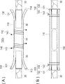
- 2A is a cross-sectional view showing a main part of the medical device for nerve regeneration in FIG. 1
- FIG. 2B is an enlarged cross-sectional view showing a 2B part surrounded by a two-dot chain line in FIG.
- FIG. 3 is a front view showing a tube body and a sleeve body constituting the contact member.
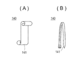
- 4 (A) and 4 (B) are front views showing a tightening body constituting the pressing member.
- FIGS. 5A and 5B are conceptual diagrams used to describe a contact member that is configured to freely swing a portion that contacts the outer periphery of a nerve.
- FIGS. 6 (A) and 6 (B) are front views used for explaining a procedure for using the medical device for nerve regeneration.
- FIG. 7 is a front view used for explaining a procedure for using the medical device for nerve regeneration.
- FIGS. 8A and 8B are front views used for explaining a procedure for using the medical device for nerve regeneration of the second embodiment.
- FIGS. 9A and 9B are front views used for explaining the use procedure of the medical device for nerve regeneration of the modified example of the second embodiment.
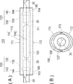
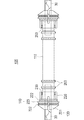
- FIGS. 10A and 10B are a front view and a left side view showing the medical device for nerve regeneration of the third embodiment.
- 11A is a cross-sectional view showing a main part of the medical device for nerve regeneration in FIG. 10, and FIG.
- FIG. 11B is an enlarged cross-sectional view showing a part 11B surrounded by a two-dot chain line in FIG.
- FIG. 12 is a perspective view showing the divided tube and the retaining ring.
- FIG. 13 is a front view showing the divided tube and the retaining ring.
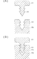
- FIGS. 14A and 14B are perspective views used for explaining the fitting portion of the sandwiching block body.
- FIGS. 15A and 15B are cross-sectional views used for explaining the fitting portion of the sandwiching block body.
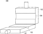
- FIG. 16 is a perspective view showing a jig used when fitting the holding block bodies together.
- FIG. 17 is a front view illustrating a medical device for nerve regeneration according to a fourth embodiment.
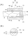
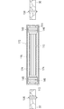
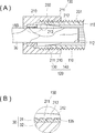
- FIG. 18A is a cross-sectional view illustrating a main part of the medical device for nerve regeneration in FIG. 17, and FIG. 18B is an enlarged cross-sectional view illustrating a part 18B surrounded by a two-dot chain line in FIG.
- FIG. 19 is a front view showing a medical device for nerve regeneration according to a fifth embodiment.
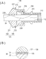
- 20A is a cross-sectional view showing a main part of the medical device for nerve regeneration in FIG. 19, and
- FIG. 20B is an enlarged cross-sectional view showing a part 20B surrounded by a two-dot chain line in FIG. FIG.
- the medical device 101 for nerve regeneration generally has a hollow tube body 110 and a connection portion 120 that connects the nerve 30 to each of both ends of the tube body 110. is doing.
- the connection unit 120 includes a contact member 130 that can freely contact the outer periphery of the nerve 30, and a pressing member 140 that applies a force to the contact member 130 to press the contact member 130 inward in the radial direction of the nerve 30. Yes.
- the contact member 130 extends in the longitudinal direction of the nerve 30. Details will be described below.
- the tube body 110 includes a space 111 into which the end of the nerve 30 is inserted.
- a space for the nerve 30 to regenerate can be secured by partitioning from surrounding tissue.
- the cross-sectional shape of the tube body 110 is not particularly limited, and various shapes can be selected according to the nerve tissue to be regenerated, such as an elliptical shape or a polygonal shape, in addition to a circular shape.
- the tube body 110 is preferably formed from a biodegradable material or a bioabsorbable material.
- the biodegradable material and the bioabsorbable material include polylactic acid, polyglycolic acid, polycaprolactone, polydioxanone, or a copolymer thereof, or polyamino acid and a copolymer thereof.
- the tube body 110 is preferably a porous body in which micropores penetrating from the outer surface side in the longitudinal direction to the inner surface side are formed from the viewpoint of allowing material exchange inside and outside the tube body.
- the present invention is not limited thereto, and the micropores do not necessarily have to be formed.
- the tube body 110 has a guide groove 112 that is formed to extend in the axial direction on at least a part of the inner peripheral surface and guides the extension of the nerve 30 (see FIGS. 2 and 3). This is because it is possible to shorten the time at which the central nerve edge and the peripheral nerve edge are joined by giving the extending direction to the regenerating nerve fibers and various related cells.
- the tube body 110 is preferably a filler 150 that is accommodated in a hollow internal space, and includes a filler 150 that includes a material that promotes the extension of the nerve 30 (see FIGS. 1 and 2). .
- a filler 150 that includes a material that promotes the extension of the nerve 30 (see FIGS. 1 and 2).
- the filler 150 include a cell adhesion factor / molecule, a nerve cell growth factor, a fibroblast growth factor, a nerve action factor, an immunoreactive factor, and an extracellular matrix (Extracellular Matrix).
- the tube body 110 and the contact member 130 are integrally formed, and the pressing member 140 is formed separately from the tube body 110.
- the contact member 130 includes a sleeve body 131 that wraps around the outer periphery of the end of the nerve 30, and the pressing member 140 includes a tightening body 141 that wraps around the outer periphery of the sleeve body 131 and fastens the sleeve body 131.
- the sleeve body 131 includes an arm piece 133 that is divided into a plurality of pieces through a slit 132 extending from an end portion. As the arm piece 133 is tightened by the tightening body 141, the arm piece 133 comes into contact with the outer periphery of the nerve 30 from a position separated from the outer periphery of the nerve 30 (see FIGS. 3, 6A, and 6B). (See FIGS. 1 and 2). In the initial state, the arm piece 133 of the sleeve body 131 is elastically flared, and the end openings 113 and 114 are wide open.
- the sleeve body 131 can form a center hole 134 having an inner diameter dimension adapted to the small-diameter nerve 30 so that the nerves 30 having different outer diameter dimensions can be held.
- the sleeve body 131 applies a resilient force that presses the nerve 30 inward in the radial direction. The nerve 30 is compressed.
- the tightening body 141 is wound around the sleeve body 131 at a position that does not exceed the sleeve body 131 along the longitudinal direction, that is, a position that overlaps the arm piece 133.
- the tightening body 141 applies a force to the sleeve body 131 to press the sleeve body 131 inward in the radial direction of the nerve 30, an appropriate form can be adopted.
- a seal tape see FIG. 4A
- a tie band see FIG. 4B
- the sleeve body 131 and the tightening body 141 are preferably formed from a biodegradable material or a bioabsorbable material, similarly to the tube body 110.
- the contact member 130 preferably includes a microprojection 135 formed on a surface facing the outer periphery of the nerve 30. This is because the contact member 130 can be prevented from slipping with respect to the outer periphery of the nerve 30 and the joint state between the nerve regeneration medical device 101 and the nerve 30 can be stably maintained.
- the minute protrusion 135 is formed on the arm piece 133 of the sleeve body 131 as the contact member 130.
- the projecting dimension of the microprojection 135 is a dimension that does not exceed the thickness of the epithelial membrane 31 of the nerve 30.
- the thickness of the epithelial membrane 31 varies depending on the site and the thickness of the nerve, but is generally in the range of 20 ⁇ m to 200 ⁇ m. Therefore, the projection dimension of the microprotrusion 135 should be selected within the range not exceeding the range of 20 ⁇ m to 200 ⁇ m, which is the thickness of the epithelial membrane 31, depending on the site and the thickness of the nerve. By doing so, it is possible to prevent the nerve bundle 32 from being crushed.
- the shape of the microprojection 135 is not particularly limited as long as the nerve 30 is difficult to be removed. However, it is preferable that the cross-sectional structure in the long axis direction is asymmetric and the nerve 30 is more difficult to escape.
- the contact member 130 includes a main body portion 130 a to which the pressing force from the pressing member 140 is transmitted, a contact portion 130 b that contacts the outer periphery of the nerve 30, and It is preferable to include a holding mechanism 160 that holds the contact portion 130b so as to be swingable with respect to the main body portion 130a. Even when the main body 130a of the contact member 130 is inclined in a direction intersecting the longitudinal direction of the nerve 30 (see FIG. 5B), the holding mechanism 160 swings the contact 130b, This is because the force by which the contact portion 130b presses the nerve 30 toward the inside in the radial direction can be evenly distributed along the longitudinal direction of the nerve 30 to prevent local concentration.
- the arm piece 133 in the sleeve body 131 as the contact member 130 is attached to the outer periphery of the nerve 30 and the main body 130 a to which the pressing force from the tightening body 141 as the pressing member 140 is transmitted. What is necessary is just to comprise from the contact part 130b which contacts, and the holding mechanism 160 which hold
- the holding mechanism 160 is preferably formed of a biodegradable material or a bioabsorbable material, as with the tube body 110.
- Nerve 30 Outer diameter 0.5-8mm
- Tube body 110 outer diameter 1 to 12 mm : Inner diameter 0.8 ⁇ 10mm : Length 10-100mm
- Sleeve body 131 Length of arm piece 133 1 to 10 mm It is.
- the arm piece 133 of the sleeve body 131 is elastically spread in a flare shape.
- the nerve end on the central side is inserted into the center hole 134 of the sleeve body 131 shown on the left side in FIGS. 6A and 6B, and the nerve end on the distal side is inserted into the center hole 134 of the sleeve body 131 shown on the right side in the figure. Insert (see FIGS. 6A and 6B).
- the elastic force that presses the nerve 30 inward in the radial direction is urged by the sleeve body 131, and the nerve 30 is compressed.
- a seal tape as the tightening body 141 is wound at a position overlapping the arm piece 133 of the sleeve body 131.
- the arm piece 133 is displaced from a position away from the outer periphery of the nerve 30 (see FIG. 7) to a position in contact with the outer periphery of the nerve 30 (see FIGS. 1 and 2). .
- a force for pressing the nerve 30 inward in the radial direction is applied to the sleeve body 131 (see FIGS. 1 and 2).
- the force for pressing the nerve 30 inward in the radial direction is evenly distributed through the arm pieces 133, and can be prevented from being concentrated locally.
- the joining of the nerve regeneration medical device 101 and the nerve 30 is completed.
- the minute projections 135 of the arm piece 133 bite into the epithelial membrane 31 of the nerve 30 to prevent the sleeve body 131 from sliding relative to the outer periphery of the nerve 30.
- the joint state between the nerve regeneration medical device 101 and the nerve 30 can be stably maintained.
- the connecting portion 120 that connects the nerve 30 to each of both ends of the tube body 110 is a contact that can freely contact the outer periphery of the nerve 30. Since it includes the member 130 and the pressing member 140 that applies a force to the contact member 130 to press the contact member 130 toward the inner side in the radial direction of the nerve 30, a suturing operation is required when joining the nerve 30. However, it is possible to easily and quickly establish the connection with the nerve 30 without requiring a high degree of skill.
- the contact member 130 has a main body part 130a to which the pressing force from the pressing member 140 is transmitted, a contact part 130b that comes into contact with the outer periphery of the nerve 30, and a holder that holds the contact part 130b in a swingable manner with respect to the main body part 130a. And the mechanism 160, the contact member 130 uniformly distributes the force pressing the nerve 30 inward in the radial direction along the longitudinal direction of the nerve 30 to prevent local concentration. it can.
- the contact member 130 includes the microprojections 135 formed on the surface facing the outer periphery of the nerve 30, the contact member 130 is prevented from sliding with respect to the outer periphery of the nerve 30, and the nerve regeneration medical device 101 and the nerve 30. Can be stably maintained.
- the protrusion dimension of the microprotrusion 135 is a dimension that does not exceed the thickness of the epithelial membrane 31 of the nerve 30, it is possible to prevent the nerve bundle 32 from being squashed.
- the contact member 130 is composed of a sleeve body 131, and the pressing member 140 is composed of a tightening body 141. With a simple structure, the contact with the nerve 30 can be established easily and quickly.
- the arm piece 133 of the sleeve body 131 is displaced from a position away from the outer periphery of the nerve 30 to a position in contact with the outer periphery of the nerve 30 as it is tightened by the tightening body 141, so that the end of the nerve 30 is wrapped. Can be held firmly.
- the tightening body 141 is wound around the sleeve body 131 at a position overlapping the arm piece 133, the force for pressing the nerve 30 toward the radially inner side is evenly distributed via the arm piece 133, Can be avoided.
- the tube body 110 includes a space portion 111 into which an end portion of the nerve 30 is inserted, and a space to be regenerated by the nerve 30 can be partitioned and secured from the periphery.
- the nerve regeneration medical device 101 by forming the nerve regeneration medical device 101 entirely from a biodegradable material or a bioabsorbable material, nerve cells regenerate and extend, and after the central nerve edge is connected to the peripheral nerve edge, the nerve regeneration medicine There is no need to remove the device 101 from the body.
- the tube body 110 has the guide groove 112 that guides the extension of the nerve 30, the direction of extension to the nerve fiber to be regenerated and various related cells is given, and the central nerve end and the peripheral nerve end are connected.
- the joining time can be shortened.
- the tube body 110 has the filler 150 containing the material accommodated in the internal space and promoting the extension of the nerve 30, it promotes the adhesion and extension of the nerve axon and promotes the regeneration of the nerve axon. it can.
- the sleeve body 131 can also be formed separately from the tube body 110.
- the sleeve body as the contact member 130 is configured to wrap around the outer periphery of the end of the nerve 30 and be inserted into the end opening of the tube body.
- the tightening body as the pressing member 140 may be configured to wind around the outer periphery of the tube body and tighten the sleeve body via the tube body.
- the medical device 102 for nerve regeneration of the second embodiment is different from that of the first embodiment in that a tightening body 142 as a pressing member 140 is slidably held in the tube body 110 in advance. Since other points are common to the first embodiment, description thereof is omitted.
- the tightening body 142 has a cylindrical shape or a C-ring shape, and is held by the tube body 110 so as to be slidable along the longitudinal direction of the tube body 110.
- the fastening body 142 is held in advance in the tube body 110 so as to be slidable. Therefore, the seal tape is attached to the tube body 110 as in the first embodiment. Compared with the winding form, the junction with the nerve 30 can be established more easily and quickly.
- the modified example of the second embodiment is different from the second embodiment in that a linear member such as a string is used as the tightening body 143.
- the fastening body 143 When a linear member such as a string is used as the fastening body 143, the fastening body 143 is slid from the central portion of the tube body 110 to both ends and fastened (see FIGS. 9A and 9B). A force for pressing the arm piece 133 toward the radially inner side of the nerve 30 can be applied to the sleeve body 131.
- a linear member such as a string
- the linear member that is the tightening body 143 is held in the tube body 110 in a slidable manner in advance, so that the seal tape is attached to the tube body 110 as in the first embodiment.
- the junction with the nerve 30 can be established more easily and quickly.
- a nerve regeneration medical device 103 according to a third embodiment will be described with reference to FIGS.
- symbol is attached
- the medical device 103 for nerve regeneration has a connection portion 120 that connects the nerve 30 to each of both ends of the tube body 110 on the outer periphery of the nerve 30.
- a contact member 130 that is freely contactable, and a pressing member 140 that applies a force to the contact member 130 to press the contact member 130 inward in the radial direction of the nerve 30 are included.
- the tube body 110 and the contact member 130 are formed separately, and the pressing member 140 is formed integrally with the tube body 110, so that the first and second embodiments are implemented. It is different from the form.
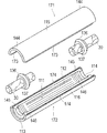
- the tube body 110 includes first and second divided tube bodies 115 and 116 that are divided into two parts in the vertical direction (see FIGS. 10A, 11A, and 12).
- the holding ring 136 as the contact member 130 is formed with a central hole 137 for inserting the nerve 30.
- the outer peripheral ring portion of the holding ring 136 has a triangular cross section.
- the pressing member 140 includes a plurality of (first and second two in the illustrated example) sandwiching block bodies 144 and 145 that sandwich the outer periphery of the contact member 130 from the radially outer side of the nerve 30.
- the first clamping block body 144 and the second clamping block body 145 can be fitted together.
- the first divided tube body 115 is integrally provided on the first holding block body 144
- the second divided tube body 116 is integrally provided on the second holding block body 145 (FIGS. 12 and 12). 13).
- the first sandwiching block body 144 and the first divided tube body 115 that are integrally formed are referred to as a first half-breaking body 171
- the second sandwiching block body 145 that is integrally formed are also referred to as a second half-broken body 172.
- the first and second half-broken bodies 171 and 172 include fitting portions 173 and 174 whose distances can be adjusted (see FIGS. 14 and 15).
- the fitting parts 173 and 174 include a convex fitting part 173 formed in the first half-cracked body 171 and a concave fitting part 174 formed in the second half-cracked body 172.
- the convex fitting portion 173 and the concave fitting portion 174 include a plurality of step portions, and depending on which step portion is to be engaged with each other, the first half-breaking body 171 and the second half-breaking portion are provided. The distance from the body 172 can be adjusted.
- the holding ring 136 is The pressing force toward the radially inner side of 30 decreases.
- the sandwiching block bodies 144 and 145 are preferably formed with engaging grooves 146 that engage with the outer peripheral portion of the retaining ring 136 on a part of the inner peripheral surface thereof (see FIG. 11A). This is because the holding ring 136 can be prevented from slipping with respect to the inner peripheral surfaces of the sandwiching block bodies 144 and 145, and the joined state between the nerve regeneration medical device 103 and the nerve 30 can be stably maintained. Further, it is preferable to provide a plurality of engaging grooves 146 along the axial direction. This is because the position where the retaining ring 146 is engaged can be selected according to the length of the nerve 30.
- the retaining ring 136 is preferably formed of an elastic material that is reduced in diameter and extended in the axial direction by applying a pressing force toward the radially inner side of the nerve 30. This is because the contact area with the outer peripheral surface of the nerve 30 is increased and the nerve 30 can be firmly held.
- the jig 180 includes a lower base 181 on which the second half-cracked body 172 is placed, and an upper base 182 that presses the first half-cracked body 171 superimposed on the second half-cracked body 172 from above. ing.
- the upper base 182 is connected to the lower base 181 through a hinge portion so as to be freely opened and closed.
- the lower base 181 is formed with an arc groove 183 that holds the second half cracked body 172
- the upper base 182 is formed with an arc groove 184 that holds the first half cracked body 171.
- the arc groove 184 of the upper base 182 is the arc groove 183 of the lower base 181. It is formed wider than.
- the contact member 130 preferably includes a microprojection 135 formed on a surface facing the outer periphery of the nerve 30. This is because the contact member 130 can be prevented from slipping with respect to the outer periphery of the nerve 30 and the joint state between the nerve regeneration medical device 103 and the nerve 30 can be stably maintained.
- the minute protrusion 135 is formed on the inner peripheral surface of the holding ring 136 as the contact member 130.
- the tube body 110 in the third embodiment also includes a space 111 into which the end of the nerve 30 is inserted, is formed from a biodegradable material or a bioabsorbable material, and is at least one of the inner peripheral surface.
- a guide groove 112 that extends in the axial direction and guides the extension of the nerve 30, and a filler 150 that contains a material that is housed in the internal space and promotes the extension of the nerve 30. This is the same as in the first embodiment.
- the main body 130a to which the pressing force from the clamping block bodies 144 and 145 as the pressing member 140 is transmitted to the ring-shaped portion of the holding ring 136 as the contact member 130; What is necessary is just to comprise from the contact part 130b which contacts the outer periphery of the nerve 30, and the holding mechanism 160 which hold
- the central nerve end is inserted into the central hole 137 of the holding ring 136 shown on the left side in FIG. 12, and the peripheral nerve end is inserted into the central hole 137 of the holding ring 136 shown on the right side in FIG. 12).
- the second holding block body 145 that is the second half-broken body 172 is placed on the lower base 181 of the jig 180.
- Each holding ring 136 holding the nerve end is set on the second holding block body 145.
- the outer peripheral portion of the holding ring 136 is engaged with the engagement groove 146 of the second holding block body 145.
- the first half cracked body 171 is stacked on the second half cracked body 172 from above.
- the upper base 182 is closed and the first and second half-broken bodies 171 and 172 are pressed against each other.
- the distance between the first half-cracked body 171 and the second half-cracked body 172 is determined by the position where the convex fitting part 173 and the concave fitting part 174 are fitted, and the nerve 30 is radially inward.
- a pressing force is applied to the retaining ring 136 (see FIG. 11).
- the jig 180 When the jig 180 is opened and the integrated first half-cracked body 171 and second half-cracked body 172 are taken out, joining of the nerve regeneration medical device 103 and the nerve 30 is completed.
- the microprotrusions 135 of the holding ring 136 bite into the epithelial membrane 31 of the nerve 30 to prevent the holding ring 136 from sliding relative to the outer periphery of the nerve 30. Further, the outer peripheral portion of the holding ring 136 is engaged with the engaging groove 146 of the holding block bodies 144 and 145, and the holding ring 136 is prevented from sliding with respect to the inner peripheral surface of the holding block bodies 144 and 145. As a result, the joint state between the nerve regeneration medical device 103 and the nerve 30 can be stably maintained.
- the connecting portion that connects the nerve 30 to each of both ends of the tube body 110. 120 includes a contact member 130 that can contact the outer periphery of the nerve 30 and a pressing member 140 that applies a force to the contact member 130 to press the contact member 130 inward in the radial direction of the nerve 30. It is possible to easily and quickly establish a joint with the nerve 30 without requiring a sewing operation when joining with the nerve 30 and without requiring a high degree of skill.
- the pressing member 140 includes a plurality of sandwiching block bodies 144 and 145 that sandwich the outer periphery of the contact member 130 from the radially outer side of the nerve 30, and the sandwiching block bodies 144 and 145 can be fitted to each other easily. With a simple structure, the junction with the nerve 30 can be established easily and quickly.
- the plurality of sandwiching block bodies 144 and 145 include fitting portions 173 and 174 whose distances can be adjusted, and the sandwiching block bodies 144 and 145 approach each other via the fitting portions 173 and 174. By separating them, the force for pressing the holding ring 136 toward the inner side in the radial direction of the nerve 30 can be increased or decreased.
- the tube body 110 is composed of the divided tube bodies 115 and 116 provided integrally with each of the plurality of sandwiching block bodies 144 and 145, the holding ring 136 and the nerve 30 are fixed by a mode and operation that sandwich the tube body 110 and the nerve 30. can do.
- the engaging groove 146 with which the outer peripheral portion of the holding ring 136 is engaged is formed on the inner peripheral surface of the sandwiching block bodies 144 and 145, the retaining ring 136 slides with respect to the inner peripheral surface of the sandwiching block bodies 144 and 145. Can be prevented, and the joint state between the nerve regeneration medical device 103 and the nerve 30 can be stably maintained.
- the holding ring 136 is formed of an elastic material that is reduced in diameter and extended in the axial direction by applying a pressing force toward the radially inward direction of the nerve 30.
- the contact area increases and the nerve 30 can be firmly held.
- the tube body 110 was comprised from the 1st and 2nd division
- segmentation tube bodies 115 and 116 was illustrated, the tube body which is not divided
- one clamping block body 144 (145) of the plurality of clamping block bodies 144 and 145 is fixed to the tube body 110, and the other clamping block body is connected to the clamping block body 144 (145).
- 145 (144) may be freely fitted.
- the holding ring 136 is exemplified as the contact member 130
- a coil spring that penetrates the nerve 30 may be used.
- An elastic material such as a coil spring is also suitable for application to the contact member 130 because it is reduced in diameter and extended in the axial direction by applying a pressing force toward the radially inward direction of the nerve 30. It will be a thing.
- a nerve regeneration medical device 104 according to the fourth embodiment will be described with reference to FIGS. 17 and 18. Note that members that are the same as those in the first to third embodiments are denoted by the same reference numerals, and description thereof is partially omitted.
- the nerve regeneration medical device 104 has connection portions 120 that connect the nerves 30 to both ends of the tube body 110 on the outer periphery of the nerve 30.
- a contact member 130 that is freely contactable, and a pressing member 140 that applies a force to the contact member 130 to press the contact member 130 inward in the radial direction of the nerve 30 are included.
- the tube body 110 includes a screw portion 201 formed at least at an end portion, and the connection portion 120 is formed on the pressing member 140 and is screwed onto the screw portion 201 of the tube body 110.
- the pressing member 140 applies a pressing force to the contact member 130 by screwing the screw portion 201 of the tube body 110 and the screw portion 202 of the pressing member 140 including the screw portion 202 that can be freely inserted.
- the tube body 110 has a threaded portion 201 formed of a male screw on the outer peripheral surface thereof.
- the screw part 201 is formed over the entire length in the longitudinal direction of the tube body.
- the pressing member 140 includes a cap 210 connected to the end of the tube body 110.
- a screw portion 202 that is screwed into the screw portion 201 of the tube body 110 is formed on the inner peripheral surface of the cap 210.
- the tube body 110 is configured to be cut freely.
- the threaded portion 201 of the tube body 110 has a length longer than the length of the threaded portion 202 of the pressing member 140, is severable, and the contact member 130 is not integrated with the tube body 110. It exists as a member. Thereby, the pressing force for pressing the nerve 30 inward in the radial direction is evenly distributed along the longitudinal direction of the nerve 30, and the length of the tube body 110 is reduced while preventing local concentration. The length corresponding to the gap dimension between the nerves 30 can be easily adjusted.
- a sleeve 211 as a contact member 130 is accommodated in the cap 210.
- the sleeve 211 includes an elastic tongue 213 formed with a tapered surface 212.
- the inner peripheral surface of the elastic tongue 213 is in contact with the outer peripheral surface of the nerve 30.
- the elastic tongue 213 is displaced inward in the radial direction when the end of the tube body 110 abuts against the tapered surface 212. As a result, a force that presses the inner side of the nerve 30 in the radial direction is applied to the sleeve 211.
- the screwing amount of the cap 210 When the screwing amount of the cap 210 is increased, the amount by which the elastic tongue portion 213 of the sleeve 211 is displaced radially inward increases, and the force for pressing the nerve 30 radially inward increases. On the other hand, when the screwing amount of the cap 210 is reduced, the amount by which the elastic tongue 213 of the sleeve 211 is displaced radially inward is reduced, and the force for pressing the nerve 30 radially inward is reduced.
- the cap 210 and the sleeve 211 are preferably formed of a biodegradable material or a bioabsorbable material, like the tube body 110.
- the contact member 130 preferably includes a microprojection 135 formed on a surface facing the outer periphery of the nerve 30. This is because the contact member 130 can be prevented from sliding with respect to the outer periphery of the nerve 30 and the joint state between the nerve regeneration medical device 104 and the nerve 30 can be stably maintained.
- the minute protrusions 135 are formed on the inner peripheral surface of the elastic tongue 213 of the sleeve 211 as the contact member 130.
- the tube body 110 in the fourth embodiment also includes a space 111 into which the end of the nerve 30 is inserted, is formed from a biodegradable material or a bioabsorbable material, and is at least one of the inner peripheral surface.
- a guide groove 112 that extends in the axial direction and guides the extension of the nerve 30, and a filler 150 that contains a material that is housed in the internal space and promotes the extension of the nerve 30. This is the same as in the first to third embodiments.
- the elastic tongue 213 in the sleeve 211 as the contact member 130, the cap 210 as the pressing member 140 and the main body 130 a to which the pressing force from the tube body 110 is transmitted What is necessary is just to comprise from the contact part 130b which contacts the outer periphery of the nerve 30, and the holding mechanism 160 which hold
- the nerve end on the central side is inserted into the cap 210 shown on the left side in FIG. 17 and the sleeve 211 inside thereof, and the nerve end on the distal side is inserted into the cap 210 shown on the right side in FIG. .
- the screwing amount of the cap 210 is adjusted to adjust the amount by which the elastic tongue 213 is displaced radially inward. That is, when it is desired to increase the pressing force, the screwing amount of the cap 210 is increased, and the amount by which the elastic tongue 213 is displaced radially inward is increased. On the other hand, when it is desired to reduce the pressing force, the screwing amount of the cap 210 may be reduced to reduce the amount by which the elastic tongue 213 is displaced radially inward.
- the joining of the nerve regeneration medical device 104 and the nerve 30 is completed.
- the microprotrusions 135 of the elastic tongue 213 bite into the epithelial membrane 31 of the nerve 30 to prevent the sleeve 211 from sliding relative to the outer periphery of the nerve 30.
- the joint state between the nerve regeneration medical device 104 and the nerve 30 can be stably maintained.
- the connection unit 120 that connects the nerve 30 to each of both ends of the tube body 110 includes the nerve 30. Since the contact member 130 includes a contact member 130 that can contact the outer periphery and a pressing member 140 that applies a force to the contact member 130 to press the contact member 130 inward in the radial direction of the nerve 30. Sometimes, a stitching operation is not required, and the connection with the nerve 30 can be established easily and quickly without requiring a high degree of skill.
- a nerve regeneration medical device 105 according to a fifth embodiment will be described with reference to FIGS. 19 and 20. Note that members that are the same as those in the first to fourth embodiments are denoted by the same reference numerals, and description thereof is partially omitted.
- the nerve regeneration medical device 105 includes a connection portion 120 that connects the nerve 30 to each of both ends of the tube body 110.
- a contact member 130 that is freely contactable, and a pressing member 140 that applies a force to the contact member 130 to press the contact member 130 inward in the radial direction of the nerve 30 are included.
- the pressing member 140 applies a pressing force to the contact member 130 by engaging the first engaging portion of the contact member 130 and the second engaging portion of the pressing member 140.
- the contact member 130 includes a sleeve portion 221 formed integrally with the cap portion 220, and the first engagement portion includes a ring groove 222 formed on the outer surface of the sleeve portion 221. Is done. Referring to FIG. 20A, a plurality of ring grooves 222 may be provided on the tapered outer surface of sleeve portion 221, preferably three or more.
- the pressing member 140 includes a stopper ring 223, and the stopper ring 223 functions as a second engagement portion that engages with the first engagement portion, that is, fits into the ring groove 222.
- the stopper ring 223 as the pressing member 140 is fitted into the ring groove 222 on the outer peripheral surface of the sleeve portion 221.
- the sleeve portion 221 is displaced inward in the radial direction when the stopper ring 223 is fitted into the ring groove 222.
- a force pressing toward the inner side in the radial direction of the nerve 30 is applied to the sleeve portion 221.
- the cap 220 and the stopper ring 223 are preferably formed of a biodegradable material or a bioabsorbable material, similarly to the tube body 110.
- An engagement ring portion 203 is formed on the outer peripheral surface of the tube body 110.
- an engagement claw 204 that engages with the engagement ring portion 203 of the tube body 110 is formed on the inner peripheral surface of the cap 220 connected to the end of the tube body 110.
- the length of the tube body 110 can be adjusted by providing a plurality of engagement ring portions 203. That is, the tube body 110 has a plurality of engagement ring portions 203, and the contact member 130 is not integrated with the tube body 110 and exists as a single member. It is possible to select one engagement ring portion 203 that engages. Thereby, the pressing force for pressing the nerve 30 inward in the radial direction is evenly distributed along the longitudinal direction of the nerve 30, and the length of the tube body 110 is reduced while preventing local concentration. The length corresponding to the gap dimension between the nerves 30 can be easily adjusted.
- the contact member 130 includes a microprojection 135 formed on a surface facing the outer periphery of the nerve 30. This is because the contact member 130 can be prevented from slipping with respect to the outer periphery of the nerve 30 and the joint state between the nerve regeneration medical device 105 and the nerve 30 can be stably maintained.
- the fine protrusion 135 is formed on the inner peripheral surface of the sleeve portion 221 as the contact member 130.
- the tube body 110 in the fifth embodiment also includes a space 111 into which the end of the nerve 30 is inserted, is formed from a biodegradable material or a bioabsorbable material, and is at least one of the inner peripheral surface.
- a guide groove 112 that extends in the axial direction and guides the extension of the nerve 30, and a filler 150 that contains a material that is housed in the internal space and promotes the extension of the nerve 30.
- the holding mechanism 160 is applied, the sleeve portion 221 as the contact member 130 is brought into contact with the outer periphery of the nerve 30 and the main body portion 130 a to which the pressing force from the stopper ring 223 as the pressing member 140 is transmitted. What is necessary is just to comprise from the contact part 130b and the holding mechanism 160 which hold
- the nerve end on the central side is inserted into the sleeve portion 221 of the cap 220 shown on the left side in FIG. 19, and the nerve end on the distal side is inserted into the sleeve portion 221 of the cap 220 shown on the right side in FIG.
- the stopper ring 223 is slid to the outer peripheral surface of the sleeve portion 221.
- the stopper ring 223 is fitted into the ring groove 222, and the sleeve portion 221 is displaced inward in the radial direction.
- a pressing force that presses the nerve 30 inward in the radial direction is applied to the elastic sleeve portion 221 (see FIG. 20A).
- the combination of the ring groove 222 and the stopper ring 223 is changed. That is, when it is desired to increase the pressing force, the position where the stopper ring 223 is fitted is changed from the center ring groove 222 shown in FIG. 20A to the left ring groove 222, and the sleeve portion 221 is moved radially inward. Increase the amount of displacement. Conversely, when it is desired to reduce the pressing force, the position where the stopper ring 223 is fitted is changed from the central ring groove 222 to the right ring groove 222, and the amount by which the elastic sleeve portion 221 is displaced radially inward is changed. You can reduce it.
- the cap 220 After engaging the ring groove 222 and the stopper ring 223 and attaching the cap 220 to the nerve 30, the cap 220 is inserted into the end of the tube body 110.
- the engaging claw 204 of the cap 220 is engaged with the engaging ring portion 203 of the tube body 110, and the cap 220 is connected to the tube body 110.
- the connection between the nerve regeneration medical device 105 and the nerve 30 is completed.
- the microprotrusions 135 of the elastic tongue 213 bite into the epithelial membrane 31 of the nerve 30 to prevent the sleeve portion 221 from sliding relative to the outer periphery of the nerve 30.
- the joint state between the nerve regeneration medical device 105 and the nerve 30 can be stably maintained.
- the connection portion 120 that connects the nerve 30 to each of both ends of the tube body 110 includes the nerve 30.
- the contact member 130 includes a contact member 130 that can contact the outer periphery and a pressing member 140 that applies a force to the contact member 130 to press the contact member 130 inward in the radial direction of the nerve 30.
- a stitching operation is not required, and the connection with the nerve 30 can be established easily and quickly without requiring a high degree of skill.
- the force for pressing the nerve 30 radially inward can be adjusted only by changing the position of the ring groove 222 into which the stopper ring 223 is fitted.
- the nerve regeneration medical devices 101 to 105 have been described with respect to the illustrated embodiment and modifications. However, the present invention is not limited to this, and constitutes the nerve regeneration medical devices 101 to 105. Each part can be replaced with any component that can exhibit the same function. Moreover, arbitrary components may be added.
- Nerve regeneration medical device 110 tube body, 111 space, 112 guide groove, 113, 114 end opening, 115 a first divided tube body; 116 second divided tube body; 120 connections, 130 contact member, 130a body part, 130b contact part, 131 sleeve body, 132 slits, 133 arm pieces, 135 microprotrusions, 136 retaining ring, 140 pressing member, 141, 142, 143 tightening body, 144
Landscapes
- Health & Medical Sciences (AREA)
- Surgery (AREA)
- Life Sciences & Earth Sciences (AREA)
- Medical Informatics (AREA)
- Nuclear Medicine, Radiotherapy & Molecular Imaging (AREA)
- Engineering & Computer Science (AREA)
- Biomedical Technology (AREA)
- Heart & Thoracic Surgery (AREA)
- Neurology (AREA)
- Molecular Biology (AREA)
- Animal Behavior & Ethology (AREA)
- General Health & Medical Sciences (AREA)
- Public Health (AREA)
- Veterinary Medicine (AREA)
- Prostheses (AREA)
- Surgical Instruments (AREA)
Abstract
Le problème à résoudre dans le cadre de la présente invention consiste à fournir un dispositif médical pour la régénération des nerfs qui ne nécessite aucun travail de suture lorsqu'il est raccordé à un nerf, et qui est apte à établir facilement et rapidement un raccordement avec un nerf sans nécessiter de compétences de pointe. La solution proposée est un dispositif médical pour la régénération des nerfs (101) comprenant un corps de tube creux (110), et des parties de raccordement (120) destinées à raccorder un nerf (30) aux deux extrémités du corps de tube. Les parties de raccordement comprennent un élément de contact (130) qui vient librement en contact avec la périphérie externe du nerf, et un élément de pression (140) appliquant une force audit élément de contact, qui appuie sur l'élément de contact en direction de l'intérieur du nerf dans la direction radiale.
Applications Claiming Priority (2)
| Application Number | Priority Date | Filing Date | Title |
|---|---|---|---|
| JP2011076731A JP2014113170A (ja) | 2011-03-30 | 2011-03-30 | 神経再生用医療デバイス |
| JP2011-076731 | 2011-03-30 |
Publications (1)
| Publication Number | Publication Date |
|---|---|
| WO2012133019A1 true WO2012133019A1 (fr) | 2012-10-04 |
Family
ID=46930750
Family Applications (1)
| Application Number | Title | Priority Date | Filing Date |
|---|---|---|---|
| PCT/JP2012/057111 Ceased WO2012133019A1 (fr) | 2011-03-30 | 2012-03-21 | Dispositif médical pour la régénération des nerfs |
Country Status (2)
| Country | Link |
|---|---|
| JP (1) | JP2014113170A (fr) |
| WO (1) | WO2012133019A1 (fr) |
Cited By (7)
| Publication number | Priority date | Publication date | Assignee | Title |
|---|---|---|---|---|
| WO2017079726A1 (fr) | 2015-11-06 | 2017-05-11 | Axogen Corporation | Connecteur et enveloppe pour coaptation de nerf du bout vers le côté |
| WO2022221465A1 (fr) * | 2021-04-13 | 2022-10-20 | The General Hospital Corporation | Pince de liaison tissulaire photochimique et chambre d'irradiation et procédé d'utilisation associé |
| EP4082448A1 (fr) * | 2021-04-26 | 2022-11-02 | Tissium SA | Conduit nerveux |
| US11633188B2 (en) | 2017-07-26 | 2023-04-25 | Neuraptive Therapeutics, Inc. | Device and method of creating a fluid containment field for administering therapeutics to a nerve |
| AU2018258064B2 (en) * | 2017-04-25 | 2024-03-14 | Axogen Corporation | Materials and methods for protecting against neuromas |
| WO2024079229A1 (fr) * | 2022-10-12 | 2024-04-18 | Tissium S.A. | Conduit de nerf |
| WO2024141431A1 (fr) | 2022-12-27 | 2024-07-04 | Tissium S.A. | Système de conduits nerveux |
Families Citing this family (2)
| Publication number | Priority date | Publication date | Assignee | Title |
|---|---|---|---|---|
| KR101608618B1 (ko) * | 2015-05-11 | 2016-04-01 | 주식회사 제네웰 | 신경재생도관 및 그 제조방법 |
| KR102082726B1 (ko) * | 2017-08-03 | 2020-02-28 | 고려대학교산학협력단 | 신경문합용 인공도관 |
Citations (4)
| Publication number | Priority date | Publication date | Assignee | Title |
|---|---|---|---|---|
| US4870966A (en) * | 1988-02-01 | 1989-10-03 | American Cyanamid Company | Bioabsorbable surgical device for treating nerve defects |
| WO2002047557A1 (fr) * | 2000-12-15 | 2002-06-20 | The University Of Nottingham | Regeneration de nerf |
| US20030204197A1 (en) * | 2002-04-26 | 2003-10-30 | Medtronic, Inc. | Sintered titanium tube for the management of spinal cord injury |
| CN1986006A (zh) * | 2005-12-20 | 2007-06-27 | 广州知光生物科技有限公司 | 生物型神经导管 |
-
2011
- 2011-03-30 JP JP2011076731A patent/JP2014113170A/ja not_active Withdrawn
-
2012
- 2012-03-21 WO PCT/JP2012/057111 patent/WO2012133019A1/fr not_active Ceased
Patent Citations (4)
| Publication number | Priority date | Publication date | Assignee | Title |
|---|---|---|---|---|
| US4870966A (en) * | 1988-02-01 | 1989-10-03 | American Cyanamid Company | Bioabsorbable surgical device for treating nerve defects |
| WO2002047557A1 (fr) * | 2000-12-15 | 2002-06-20 | The University Of Nottingham | Regeneration de nerf |
| US20030204197A1 (en) * | 2002-04-26 | 2003-10-30 | Medtronic, Inc. | Sintered titanium tube for the management of spinal cord injury |
| CN1986006A (zh) * | 2005-12-20 | 2007-06-27 | 广州知光生物科技有限公司 | 生物型神经导管 |
Cited By (23)
| Publication number | Priority date | Publication date | Assignee | Title |
|---|---|---|---|---|
| JP7377248B2 (ja) | 2015-11-06 | 2023-11-09 | アクソジェン コーポレイション | 神経端側吻合のためのコネクタおよびラップ |
| JP7372963B2 (ja) | 2015-11-06 | 2023-11-01 | アクソジェン コーポレイション | 神経端側吻合のためのコネクタおよびラップ |
| JP2018535806A (ja) * | 2015-11-06 | 2018-12-06 | アクソジェン コーポレイション | 神経端側吻合のためのコネクタおよびラップ |
| EP3370624A4 (fr) * | 2015-11-06 | 2019-07-31 | Axogen Corporation | Connecteur et enveloppe pour coaptation de nerf du bout vers le côté |
| US10835253B2 (en) * | 2015-11-06 | 2020-11-17 | Axogen Corporation | Connector and wrap for end-to-side nerve coaptation |
| AU2016349525B2 (en) * | 2015-11-06 | 2021-10-07 | Axogen Corporation | Connector and wrap for end-to-side nerve coaptation |
| JP2022016607A (ja) * | 2015-11-06 | 2022-01-21 | アクソジェン コーポレイション | 神経端側吻合のためのコネクタおよびラップ |
| IL259114B2 (en) * | 2015-11-06 | 2023-04-01 | Axogen Corp | connector and sheath for end-to-side nerve connection (es) |
| IL259114B (en) * | 2015-11-06 | 2022-12-01 | Axogen Corp | Connector and wrap for end-to-side nerve coaptation |
| US12232733B2 (en) | 2015-11-06 | 2025-02-25 | Axogen Corporation | Connector and wrap for end-to-side nerve coaptation |
| US20170128073A1 (en) * | 2015-11-06 | 2017-05-11 | Axogen Corporation | Connector and Wrap for End-to-Side Nerve Coaptation |
| WO2017079726A1 (fr) | 2015-11-06 | 2017-05-11 | Axogen Corporation | Connecteur et enveloppe pour coaptation de nerf du bout vers le côté |
| JP2022024135A (ja) * | 2015-11-06 | 2022-02-08 | アクソジェン コーポレイション | 神経端側吻合のためのコネクタおよびラップ |
| AU2018258064B2 (en) * | 2017-04-25 | 2024-03-14 | Axogen Corporation | Materials and methods for protecting against neuromas |
| US11633188B2 (en) | 2017-07-26 | 2023-04-25 | Neuraptive Therapeutics, Inc. | Device and method of creating a fluid containment field for administering therapeutics to a nerve |
| US12383273B2 (en) | 2017-07-26 | 2025-08-12 | Neuraptive Therapeutics, Inc. | Device and method of creating a fluid containment field for administering therapeutics to a nerve |
| WO2022221465A1 (fr) * | 2021-04-13 | 2022-10-20 | The General Hospital Corporation | Pince de liaison tissulaire photochimique et chambre d'irradiation et procédé d'utilisation associé |
| WO2022229207A1 (fr) | 2021-04-26 | 2022-11-03 | Tissium S.A. | Conduit de nerf |
| EP4082448A1 (fr) * | 2021-04-26 | 2022-11-02 | Tissium SA | Conduit nerveux |
| WO2024079229A1 (fr) * | 2022-10-12 | 2024-04-18 | Tissium S.A. | Conduit de nerf |
| WO2024078716A1 (fr) * | 2022-10-12 | 2024-04-18 | Tissium S.A. | Conduit nerveux |
| WO2024141431A1 (fr) | 2022-12-27 | 2024-07-04 | Tissium S.A. | Système de conduits nerveux |
| WO2024141155A1 (fr) * | 2022-12-27 | 2024-07-04 | Tissium S.A. | Système de conduit nerveux |
Also Published As
| Publication number | Publication date |
|---|---|
| JP2014113170A (ja) | 2014-06-26 |
Similar Documents
| Publication | Publication Date | Title |
|---|---|---|
| WO2012133019A1 (fr) | Dispositif médical pour la régénération des nerfs | |
| JP4669871B2 (ja) | 隣接して配置された骨板を固定するための外科用接続要素 | |
| US8403017B2 (en) | System, method and apparatus for making tapered looped suture | |
| EP2168755A2 (fr) | Système et procédé de fabrication de suture biseautée à boucle | |
| KR101377429B1 (ko) | 외과 수술용 결찰클립 | |
| CN109730734B (zh) | 缝合锚组件 | |
| US20110046651A1 (en) | Multifunctional core for two-piece hemostasis clip | |
| US12213663B2 (en) | Suture needle devices and suture attachment methods | |
| TWI623296B (zh) | 用於脫髮治療的具有單個或多個金線的雙針組 | |
| US20200297402A1 (en) | Load Distributor For A Sternum Closure Device And Tool For Cutting The Load Distributor | |
| US20180353183A1 (en) | Connector, medical clip device and method for producing medical clip device | |
| RU2728569C2 (ru) | Шовная нить, имеющая удерживающий элемент на конце, и способ ее применения | |
| US20140288595A1 (en) | Soft tissue interference fit anchor system | |
| JP7447109B2 (ja) | 接合アセンブリ及び接合アセンブリで使用するための固定装置 | |
| JP2012210255A (ja) | 神経再生用医療デバイス | |
| KR20200016077A (ko) | 위치 수정이 가능한 멀티 필라멘트 폴리디옥사논 봉합사의 침관 결합구조 | |
| JP2025061964A (ja) | 人体組織に対して細長い可撓性要素のu字形部を支持するための方法及び装置 | |
| KR101898188B1 (ko) | 멀티 필라멘트 폴리디옥사논 봉합사 및 침관의 결합구조 | |
| JP2012210256A (ja) | 神経再生用医療デバイス | |
| WO2020250603A1 (fr) | Connecteur de type y équipé d'une valve hémostatique | |
| KR101189560B1 (ko) | 바늘이 부착된 봉합사 | |
| US20230200824A1 (en) | Medical clip and method for producing a medical clip | |
| US20210338300A1 (en) | Cable crimp cap apparatus and method | |
| JP7478384B1 (ja) | 釣り糸止め具及び釣り糸止め具セット | |
| JP6165404B1 (ja) | 糸固定具 |
Legal Events
| Date | Code | Title | Description |
|---|---|---|---|
| 121 | Ep: the epo has been informed by wipo that ep was designated in this application |
Ref document number: 12764752 Country of ref document: EP Kind code of ref document: A1 |
|
| NENP | Non-entry into the national phase |
Ref country code: DE |
|
| 122 | Ep: pct application non-entry in european phase |
Ref document number: 12764752 Country of ref document: EP Kind code of ref document: A1 |
|
| NENP | Non-entry into the national phase |
Ref country code: JP |