WO2012133228A1 - Appareil de traitement d'images et son programme - Google Patents
Appareil de traitement d'images et son programme Download PDFInfo
- Publication number
- WO2012133228A1 WO2012133228A1 PCT/JP2012/057604 JP2012057604W WO2012133228A1 WO 2012133228 A1 WO2012133228 A1 WO 2012133228A1 JP 2012057604 W JP2012057604 W JP 2012057604W WO 2012133228 A1 WO2012133228 A1 WO 2012133228A1
- Authority
- WO
- WIPO (PCT)
- Prior art keywords
- image
- foreign object
- object shadow
- processing apparatus
- captured image
- Prior art date
- Legal status (The legal status is an assumption and is not a legal conclusion. Google has not performed a legal analysis and makes no representation as to the accuracy of the status listed.)
- Ceased
Links
Images





Classifications
-
- H—ELECTRICITY
- H04—ELECTRIC COMMUNICATION TECHNIQUE
- H04N—PICTORIAL COMMUNICATION, e.g. TELEVISION
- H04N1/00—Scanning, transmission or reproduction of documents or the like, e.g. facsimile transmission; Details thereof
- H04N1/40—Picture signal circuits
- H04N1/409—Edge or detail enhancement; Noise or error suppression
- H04N1/4097—Removing errors due external factors, e.g. dust, scratches
-
- G—PHYSICS
- G06—COMPUTING OR CALCULATING; COUNTING
- G06T—IMAGE DATA PROCESSING OR GENERATION, IN GENERAL
- G06T5/00—Image enhancement or restoration
- G06T5/50—Image enhancement or restoration using two or more images, e.g. averaging or subtraction
-
- G—PHYSICS
- G06—COMPUTING OR CALCULATING; COUNTING
- G06T—IMAGE DATA PROCESSING OR GENERATION, IN GENERAL
- G06T5/00—Image enhancement or restoration
- G06T5/77—Retouching; Inpainting; Scratch removal
-
- H—ELECTRICITY
- H04—ELECTRIC COMMUNICATION TECHNIQUE
- H04N—PICTORIAL COMMUNICATION, e.g. TELEVISION
- H04N23/00—Cameras or camera modules comprising electronic image sensors; Control thereof
- H04N23/80—Camera processing pipelines; Components thereof
- H04N23/81—Camera processing pipelines; Components thereof for suppressing or minimising disturbance in the image signal generation
- H04N23/811—Camera processing pipelines; Components thereof for suppressing or minimising disturbance in the image signal generation by dust removal, e.g. from surfaces of the image sensor or processing of the image signal output by the electronic image sensor
Definitions
- the present invention relates to an image processing apparatus and an image processing program.
- Patent Document 1 a technique is known in which a foreign object is detected from a change in transmittance (change in luminance information in each pixel) due to a foreign object shadow in an image to be corrected, and correction for deleting the foreign object shadow is performed (see Patent Document 1).
- the above prior art needs to capture a reference image in which foreign matter is reflected.
- the coordinates of the foreign substance position may differ between the captured image and the reference image.
- An object of the present invention is to provide an image processing apparatus and an image processing program that can more easily detect foreign matter in a captured image.
- the position selection unit capable of selecting a specific position in the first photographed image, and a constant including the position selected by the position selection unit in the first photographed image.
- a range determining unit for determining a range; an image selecting unit for selecting a second captured image different from the first captured image; and the predetermined range of the first captured image in the second captured image
- a foreign object shadow information acquisition unit that acquires foreign object shadow information that has moved into the second captured image from a corresponding range corresponding to the image processing apparatus.
- the image selection unit may select an image shot under shooting conditions close to the shooting conditions of the first shot image as the second shot image.
- the imaging condition is that the camera body is the same as the camera body that captured the first captured image, and at least one of an aperture value, an imaging distance, a lens, a focal length, and an imaging time. May be the same.
- the foreign object shadow information acquisition unit may acquire the foreign object shadow information using luminance information.
- the image selection unit has the foreign object shadow information in the corresponding range when the second captured image has the same file type as the first captured image, and You may select the image whose brightness
- the image selection unit has the foreign object shadow information in the corresponding range when the second captured image has the same file type as the first captured image, and An image whose hue around the range is the same as or closest to the first photographed elephant image may be selected.
- the image selection unit selects, as the second captured image, an image having the foreign object shadow information in the corresponding range and having the smallest standard deviation of luminance around the corresponding range. May be.
- the image selection unit may create data for correcting the first photographed image from a brightness profile averaged over the corresponding range in the second photographed image.
- the image selection unit may select a photographed image other than the first photographed image with a different shutter speed as the second photographed image.
- the image processing apparatus may include an image correction unit.
- the second photographed image for selecting the second photographed image for acquiring the foreign object shadow information from the stored photographed image based on the photographing condition of the first photographed image to be corrected.
- the selection unit extracts a foreign object shadow candidate that may be a foreign object shadow from among the shadows reflected in the captured image, and for each captured image, coordinates of the position where the foreign object shadow candidate exists and the coordinates
- the foreign object shadow information acquisition unit that acquires the luminance reduction amount of the foreign object shadow candidate part, the coordinates of the position where the foreign object shadow candidate exists in the second captured image, and the foreign object shadow acquired by the foreign object shadow information acquisition unit
- an image processing apparatus comprising: a correction unit that corrects the first captured image based on a luminance decrease amount of a candidate portion.
- the second photographed image for selecting the second photographed image for acquiring the foreign object shadow information from the stored photographed image based on the photographing condition of the first photographed image to be corrected extracts a foreign object shadow candidate that may be a foreign object shadow from among the shadows reflected in the captured image, and for each captured image, coordinates of the position where the foreign object shadow candidate exists and the coordinates
- a foreign object shadow information acquisition unit that acquires a luminance decrease amount of a part of the foreign object shadow candidate, and adopts the foreign object shadow candidate as a foreign object shadow, and the coordinates of the foreign object shadow candidate acquired by the foreign object shadow information acquisition unit are
- An image processing apparatus comprising: a display unit configured to display a first photographed image.
- the second photographed image selection unit may select an image photographed under photographing conditions close to the photographing condition of the first photographed image as the second photographed image.
- 2nd aspect or 3rd aspect WHEREIN The said imaging conditions are the camera body same as the camera body which image
- the standard deviation of the peripheral brightness of the foreign object shadow candidate in the second photographed image is a threshold value or more, the foreign object shadow candidate is not adopted as the foreign object shadow.
- the foreign object shadow candidate when the standard deviation of a certain range including the position of coordinates corresponding to the foreign object shadow candidate in the first photographed image is equal to or smaller than a threshold value, the foreign object shadow candidate is determined as the foreign object shadow.
- the image processing apparatus is characterized in that it is not employed.
- the second photographed image selection unit there are a plurality of second photographed images selected by the second photographed image selection unit, and foreign object shadow candidates existing at the same coordinate positions are derived from the plurality of second photographed images. If selected, a certain range of hues including the foreign object shadow candidate and a certain range of hues including the portion corresponding to the position of the coordinate in the first captured image are the closest foreign object shadow candidates of the second captured image. Is used as a foreign object shadow.
- the selection unit that selects the second captured image, and the foreign object information that is information regarding the foreign object shadow from the second captured image are acquired.
- a position selection unit capable of selecting a specific position in the first photographed image, a range determination unit for determining a certain range including the position selected by the position selection unit, An image selection unit that selects a second captured image different from the one captured image, and a foreign object shadow information acquisition unit that acquires foreign object shadow information from a corresponding range corresponding to the certain range in the second captured image.
- the sixth aspect of the present invention provides an image processing program for causing a computer to execute the function of the image processing apparatus of the above aspect.
- FIG. 1 is a block diagram illustrating a personal computer and peripheral devices that constitute a camera and an image processing apparatus.
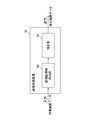
- 1 is a functional block diagram of an image processing apparatus that performs an image defect correction process according to a first embodiment.
- FIG. 3 is a functional block diagram of a defect determination unit in the image processing apparatus according to the first embodiment. It is a flowchart explaining the flow of the foreign matter shadow information detection by the image processing apparatus of 1st Embodiment, and the correction process of an image. It is an example of the 1st picked-up image displayed on the monitor in 1st Embodiment and 2nd Embodiment.
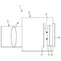
- FIG. 1 is a diagram illustrating a configuration of a lens-interchangeable camera 1.
- FIG. 2 is a block diagram showing a personal computer (PC) 30 and peripheral devices constituting the camera 1 and the image processing apparatus.
- the camera 1 is an electronic still camera that outputs image data obtained by converting a subject image into an electrical signal.
- image data captured by the camera 1 is acquired by a PC 30 functioning as an image processing apparatus, and foreign object shadow detection and correction processing described later is performed.
- the camera 1 includes a camera body 2 and an imaging lens 3 that can be attached to and detached from the camera body 2.
- the imaging lens 3 includes an imaging optical system 3L having a plurality of optical lens groups (shown as one lens in FIG. 1).
- the camera body 2 includes a shutter 11, an optical filter 12, an image sensor 13, an image processing unit 14, an operation unit 15, a display unit 16, a memory card interface (hereinafter referred to as “memory card IF”) 17, an external interface (hereinafter referred to as “memory card IF”). , “External IF”) 18, a power source (not shown), a control unit 20 and the like.
- the shutter 11 adjusts the exposure time by shielding and passing photographing light from the imaging optical system 3L toward the image sensor 13.
- the optical filter 12 is configured by an optical low-pass filter or the like that prevents generation of false colors (color moire) or the like during imaging.
- reference numeral 4 in FIG. 1 indicates foreign matters such as dust and dirt attached to the surface of the optical filter 12. If the foreign matter 4 is attached to the optical filter 12 that is on the optical path of the photographing light and transmits the photographing light, pixels that are affected by the foreign matter shadow in the image data acquired by the image sensor 13. May be included.
- the imaging element 13 is a photoelectric conversion element such as a CCD or CMOS, and has a rectangular imaging area composed of a plurality of pixels.
- the image sensor 13 converts the image formed on the image plane into an electrical signal and outputs an image signal (imaging signal) corresponding to the subject image.
- the image signal output from the image sensor 13 is A / D converted and input to the image processing unit 14 after predetermined analog signal processing.
- the image processing unit 14 performs image processing such as interpolation, gradation conversion, and edge enhancement on the image data input from the image sensor 13.
- the operation unit 15 includes a release button for inputting a signal for determining a shooting timing by the photographer, a selection button for mode switching, and the like. And the operation part 15 inputs those operation information into a control part.
- the display unit 16 is configured by an LCD or the like, and displays various setting menus in the camera 1, a reproduced image based on an image captured by the image sensor 13 and image data stored in a memory card.
- the memory card IF 17 serves as an interface with a memory card (card-like removable memory) 40.
- the external IF 18 serves as an interface with an external device such as the PC 30 via a predetermined cable or a wireless transmission path.
- the power supply supplies power to each functional unit of the camera 1.
- the control unit 20 controls each functional unit in the camera 1 in an integrated manner. That is, when a shooting instruction signal is input from the release switch in the operation unit 15, the control unit 20 controls the driving of the shutter 11 to control a shooting operation such as an exposure operation. Further, the control unit 20 stores the image data acquired by the image sensor 13 and subjected to image processing by the image processing unit 14 in a memory card 40 or the like that is detachably attached to the memory card IF 17. ,save. Further, the control unit 20 calls the image data stored in the memory card 40 or the like and causes the display unit 16 to display the image data.
- the camera 1 configured as described above is controlled by the control unit 20 at the time of shooting and operates as follows.
- the release button of the operation unit 15 is pressed by the operator, the shutter 11 is opened for a predetermined time.
- the imaging device 13 generates an image signal corresponding to the optical image formed in the imaging region by the imaging optical system 3L.
- the image signal generated by the image sensor 13 is input as image data to the image processing unit 14 and is subjected to predetermined image processing by the image processing unit 14.
- the captured image is displayed on the display unit 16 based on the image data processed by the image processing unit 14, and the image data is subjected to compression processing by JPEG, RAW, or the like as necessary, and is stored in the memory card IF 17.
- image data is sent to a PC 30 (described later) connected via the external IF 18.
- the image data stored / saved in the memory card 40 or transmitted to the PC 30 via the external IF 18 is recorded in, for example, an Exif (EXchange Image File format) file.
- Exif EXchange Image File format
- additional information such as the camera body 2 type, camera manufacturer name, imaging pixel information, aperture value (F value) and exposure conditions such as focus, shutter speed and exposure correction, shooting time, and shooting distance are recorded together. Is done.
- the personal computer (PC) 30 serves as an interface with an external device such as the camera 1 via a memory card IF, a cable, or a wireless transmission path that serves as an interface with the CPU, memory, hard disk, and memory card 40. External IF etc. are provided.
- the PC 30 is connected to a monitor 31, a printer 32, and the like as an image display unit, and the user arbitrarily selects a specific position where a foreign object such as a foreign object shadow appears in a captured image displayed on the monitor 31.
- a mouse 34 is connected as a selection unit to be indicated.
- the CD-ROM 33 connected to the PC 30 is preinstalled with an application program for detecting a foreign object such as a foreign object shadow and correcting the image based on information of the detected foreign object.
- the foreign object shadow information detection / correction processing is performed by the PC 30 on the image data after completion of image processing provided via the memory card 30 or transmitted from the external interface 18 of the camera 1.
- the foreign object shadow information detection and image correction processing application program is installed in the PC 30, and the PC 30 executes the program to perform foreign object shadow information detection and image correction processing. It functions as the device 50.
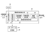
- FIG. 3 is a functional block diagram of the image processing apparatus 50 that performs foreign object shadow information detection / correction processing.
- FIG. 4 is a functional block diagram of the foreign object shadow information detection unit 60 in the image processing apparatus 50.
- the image processing apparatus 50 functioning by the PC 30 and the program is based on the foreign object shadow information detection unit 60 that detects foreign object shadow information and the foreign object shadow information detected by the foreign object shadow information detection unit 60.
- a correction unit 56 that corrects the foreign object shadow caused by the foreign object.
- the foreign object shadow information detection unit 60 includes a range determination unit 61, an image selection unit 62, and a foreign object shadow information acquisition unit 63.
- the foreign object shadow information acquisition unit 63 further includes a connected region determination unit 64, a target region extraction unit 65, and a luminance determination unit 66.
- FIG. 5 is a flowchart for explaining the flow of foreign object shadow information detection and image correction processing in the image processing apparatus 50.
- the flow of foreign object shadow information detection and image correction processing in the image processing apparatus 50 will be described with reference to the flowchart of FIG. In FIG. 5 and the following description, the step is also abbreviated as “S”.
- step S01 the PC 30 including the image processing device 50 reads data of the first captured image G1 (correction target) input via the memory card 40 or the external interface 18 of the camera 1. .
- step S02 the read first photographed image G1 is displayed on the monitor 31.
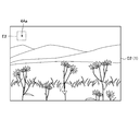
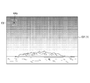
- FIG. 6 shows an example of the first captured image G1 displayed on the monitor 31.
- a foreign object shadow 4A in a portion surrounded by trees.
- Such a foreign object shadow is caused by, for example, a foreign substance (foreign substance 4) (see FIG. 1) attached to the front surface of the optical filter 12.
- the user can recognize the foreign object shadow part, but the luminance gradient of the foreign object shadow 4A and the luminance gradient of the trees overlap, and it may be difficult to detect the foreign object shadow 4A information from the luminance gradient. is there.
- step S03 when the user clicks the position of the foreign object shadow 4A of the first captured image G1 displayed on the monitor 31 with the mouse 34, the range determination unit 61 centers the click position with the mouse 34.
- a detection range E1 having a predetermined size including the foreign object shadow and its periphery is determined.
- the detection range E1 may be defined in advance, or the user may be able to set an arbitrary size by moving the mouse 34.
- step S ⁇ b> 04 the image selection unit 62 selects a second image that has the same or substantially the same image capturing condition as the first captured image G ⁇ b> 1 among the plurality of second captured images stored in the database 36 of the storage unit 35. Search and select image G2.
- the determination of the identity of the shooting conditions is performed based on shooting information represented by the Exif information of the first shot image G1 and the second shot image G2.
- the criterion is that the camera body (camera type) 2, aperture value (F value), focal length, shooting time, lens, shooting distance, etc. in the shooting information such as Exif information are the same.
- the camera body 2 is the same.
- the foreign matter attached to the optical filter 12 disposed in the camera body 2 moves to the same position as a shadow. This is because the foreign object shadow is corrected by using the.
- At least one of the other shooting conditions, in particular, the aperture values preferably match, and the shooting distance, the focal length, the shooting time, and the like are more preferably the same. More preferably, all conditions are met.
- One or more or a plurality of second captured images G2 selected by the image selection unit 62 are selected according to the selection condition. If no image is selected, a warning message such as “zero selected number” may be displayed on the monitor 31.
- 7A and 7B show a case where a plurality of second photographed images G2 are selected by the image selection unit 62, and are diagrams showing the plurality of images G2 (1) and G2 (2), respectively.
- step S05 the foreign object shadow information acquisition unit 63 specifies a corresponding range E2 corresponding to a predetermined detection range E1 in the first captured image G1 among the plurality of selected second captured images G2. .
- step S06 the connected region determination unit 64 obtains a luminance plane from the image data of each RGB pixel that forms an image in the corresponding range E2, applies inverse gamma correction to the luminance plane, and linearizes the input / output relationship. return. Then, a luminance gradient plane is generated from the luminance plane after inverse gamma correction.
- a high pixel value is shown at the peripheral part of the foreign object shadow, and a low pixel value is shown in a uniform plane such as the sky. That is, a high pixel value is shown in the edge portion, and thereby the edge portion of the foreign object shadow can be detected.
- the connected area determination unit 64 sets a predetermined threshold value and converts the luminance gradient plane into a binary image. That is, a pixel having a luminance gradient value higher than the threshold is replaced with “1”, and a pixel having a brightness gradient value lower than the threshold is replaced with “0”.
- the connected area determination unit 64 extracts an area (connected pixel area) in which “1” pixels are connected from the binary image thus obtained.
- the connected pixel region is, for example, a pixel region that is continuous (near 4) on at least one of four sides of a rectangular pixel. This connected pixel region is a region that may have a foreign object shadow.
- the target region extraction unit 65 extracts a correction candidate region from the connected pixel regions extracted by the connected region determination unit 64 based on the size (large or small) of the foreign object shadow.
- the determination of the size of the foreign object shadow in the target area extraction unit 65 is defined by the number of pixels.
- the target area extraction unit 65 uses the absolute size of the foreign object shadow as a reference when extracting the correction candidate area from the connected pixel area.
- the detection target is a size of a minimum of 100 ⁇ m ⁇ 100 ⁇ m to a maximum of 400 ⁇ m ⁇ 400 ⁇ m.
- the target area extraction unit 65 uses the area represented by the number of pixels of the foreign object shadow as a threshold, and the size (number of pixels) of the connected pixel area extracted from the binary image in the connected area determination unit 64 is the threshold. Those included are determined as foreign object shadow candidates that can be corrected, and are selected.
- the luminance determining unit 66 uses the luminance value described in the previous connected region determining unit 64 and the luminance plane corresponding to the image plane to compare the internal and external luminances in the connected pixel region.
- the dust shadow has a lower internal luminance than the peripheral luminance, and the luminance ratio (internal luminance / peripheral luminance) is much smaller than one. Therefore, a predetermined threshold value with a small luminance ratio is set, and it is determined and selected as a foreign object shadow only when the luminance ratio of the connected image region is smaller than this threshold value.
- step S11 the foreign object shadow information acquisition unit 63 acquires a gain map and foreign object position information (coordinates) in the range E2 of the second captured image G2 having a shadow determined to be a foreign object shadow.
- the standard deviation of the luminance in the range E2 in each of the plurality of second captured images G2 is calculated. Then, a photographed image in which the variance of the standard deviation of the range E2 is equal to or less than a predetermined threshold is selected from the second photographed image G2.
- the variance is equal to or less than the predetermined threshold value because the range E2 is a flat image, that is, an image with little variation in luminance, and foreign object shadows can be easily determined.
- the variance is equal to or less than a predetermined value, but it may be used that the image has few edges and the histogram is uniform.
- the gain map and foreign object position information may be obtained by averaging the gain maps of a plurality of images without narrowing down the number of images.
- an image with the closest shooting condition may be selected.
- a shutter with a different shutter speed may be selected.
- the second captured image G2 may be selected by weighting the above-described conditions (luminance, hue, standard deviation) and making a comprehensive determination.
- step S11 the correction unit 56 uses the gain map and foreign object position information (coordinates) as foreign object shadow information reflected in the second captured image G2 selected as described above. Correction is performed to correct or reduce the luminance of the foreign object shadow by correcting the captured image.
- the correction unit 56 uses the gain map acquired from the predetermined detection range E in the second captured image G2 for the predetermined detection range E in the first captured image G1, and uses the gain map acquired from the first captured image G1.
- Gain correction is performed by multiplying the luminance of the predetermined detection range E by the reciprocal of the luminance signal.
- image correction is performed to reduce or eliminate a change in luminance due to a foreign object such as a foreign object shadow appearing in a predetermined detection range E in the first captured image G1.
- the image processing apparatus 50 includes a selection unit (mouse) 34 that can arbitrarily select a specific position where a foreign object such as a foreign object is reflected in a captured image, and a fixed value including the selected position.
- a range determination unit 61 that determines a range and an image selection unit 62 that selects a second captured image different from the captured image are provided. This eliminates the troublesome trouble of shooting a reference image in which foreign objects such as a foreign object are reflected before normal shooting. For example, the first captured image to be detected displayed on the monitor 31 is displayed.
- the foreign object detection function can be executed by simply performing a simple operation of clicking (selecting) with a mouse 34 a specific position where a foreign object shadow is reflected.
- the foreign object shadow information acquisition unit 63 in the image processing device 50 includes the second captured image from the range E determined by the range determination unit 61 in the second captured image close to the imaging condition selected by the image selection unit 62. Acquire foreign object shadow information reflected inside. Thereby, the foreign object shadow information which becomes a defect in the first captured image can be detected with high accuracy. Further, it is possible to appropriately correct a defect in the captured image based on the detected foreign object shadow information.
- the foreign object shadow information in the second image selected based on the selected first captured image is acquired, and the first captured image is corrected based on the detected foreign object shadow information ( Foreign object shadow information acquisition / correction processing) is performed.
- an application program for foreign object shadow information acquisition and image correction processing is installed in the PC 30.
- the PC 30 executes foreign object shadow information acquisition and image correction processing. It functions as the image processing apparatus 150 to perform.
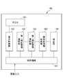
- FIG. 8 is a functional block diagram of the image processing apparatus 150 that performs foreign object shadow information acquisition / correction processing.
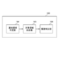
- FIG. 9 is a functional block diagram of the foreign object shadow information acquisition unit 163 in the image processing apparatus 150.
- the image processing apparatus 150 displays a storage area 151 for storing image data provided via the memory card 30 or transmitted from the external interface 18 of the camera 1, and a captured image stored in the storage area 151.
- a monitor 152 and a display control unit 153 for controlling the display are provided.
- the image processing apparatus 150 selects a foreign object shadow candidate from the captured image data stored in the storage area 151, and acquires a foreign object shadow candidate coordinate and a luminance decrease amount of the foreign object shadow candidate part. 163, a first captured image selection unit 154 that can select an image to be corrected via the mouse 34 and the like, and a second captured image is selected from the storage area 151 based on the selected first captured image. A second captured image selection unit 155, and a correction unit 156 that corrects a corresponding portion in the first captured image based on the foreign object shadow information detected by the foreign object shadow information acquisition unit 163 in the second captured image. ing.
- the foreign object shadow information acquisition unit 163 includes a connected region determination unit 164, a target region extraction unit 165, and a luminance determination unit 166.
- the foreign object shadow information acquisition unit 163 is the same as the foreign object shadow information acquisition unit 63 of the first embodiment.
- a captured image is input to the storage area 151 of the image processing apparatus 150 via the memory card 40 or the external interface 18 of the camera 1. Then, the foreign object shadow information acquisition unit 163 of the image processing apparatus 150 acquires foreign object shadow information from the captured image input to the storage area 151.
- the foreign object shadow information includes the coordinates of the position where the foreign object shadow exists, the brightness reduction amount (gain map) of the part of the foreign object shadow, and the like. This foreign object shadow information acquisition may be automatically performed when the image is transferred to the storage area, or may be started by the operation of the operator.
- FIG. 10 is a flowchart for explaining the flow of foreign object shadow information acquisition in the foreign object shadow information acquisition unit 163.
- the step is also abbreviated as “S”.
- the acquisition of foreign object shadow information in the following flowchart is the same as steps S06 to S10 in the first embodiment.
- the connected region determination unit 164 obtains a luminance plane of image data of each pixel by RGB forming an image, performs inverse gamma correction on the brightness plane, and returns the input / output relationship to linear. Then, a luminance gradient plane is generated from the luminance plane after inverse gamma correction.
- a high pixel value is shown at the peripheral part of the foreign object shadow, and a low pixel value is shown in a uniform plane such as the sky. That is, a high pixel value is shown in the edge portion, and thereby the edge portion of the foreign object shadow can be detected.
- the connected area determination unit 164 sets a predetermined threshold value and converts the luminance gradient plane into a binary image. That is, a pixel having a luminance gradient value higher than the threshold is replaced with “1”, and a pixel having a luminance gradient value lower than the threshold is replaced with “0”.
- the connected region determination unit 164 extracts a region (connected pixel region) in which the pixels “1” are connected from the binary image thus obtained.
- the connected pixel region is, for example, a pixel region that is continuous (near 4) on at least one of four sides of a rectangular pixel. This connected pixel region is a region that may have a foreign object shadow.
- step S ⁇ b> 53 the target area extraction unit 165 extracts a correction candidate area from the connected pixel areas extracted by the connected area determination unit 164 based on the size (large or small) of the foreign object shadow.
- the determination of the size of the foreign object shadow in the target area extraction unit 165 is defined by the number of pixels.
- the target area extraction unit 165 uses the absolute size of the foreign object shadow as a reference when extracting the correction candidate area from the connected pixel area.
- the detection target is a size of a minimum of 100 ⁇ m ⁇ 100 ⁇ m to a maximum of 400 ⁇ m ⁇ 400 ⁇ m.
- the target area extraction unit 165 uses the area represented by the number of pixels of the foreign object shadow as a threshold, and the size (number of pixels) of the connected pixel area extracted from the binary image by the connected area determination unit 164 is the threshold. Select what is contained within.
- the luminance determination unit 166 uses the luminance value V (Value) obtained by the HSV conversion described in the previous connected region determination unit 164 and the luminance plane corresponding to the image plane, and uses the luminance value V (Value) in the connected pixel region. Compare brightness.
- the foreign object shadow has a lower internal luminance than the peripheral luminance, and the luminance ratio (internal luminance / peripheral luminance) is much smaller than one. For this reason, a predetermined threshold value with a small luminance ratio is set, and it is determined as a foreign object shadow only when the luminance ratio of the connected image region is smaller than this threshold value.
- the standard deviation of the brightness in a certain range around the foreign object shadow is equal to or greater than the threshold, it is not adopted as the foreign object shadow. This is because when the standard deviation of the brightness around the detected foreign object shadow is large, the reliability of the actual foreign object shadow is low due to the shadow on the texture.
- step S55 the foreign object shadow information acquisition unit 163 acquires the brightness decrease amount of the foreign object shadow and the foreign object position information (coordinates), and stores them in the storage area 151 in association with each captured image.
- FIG. 11 is a flowchart showing the foreign object shadow removal operation.
- the display control unit 153 of the PC causes the monitor 152 to display the captured image stored in the storage area 151 based on the operation of the PC operation unit 34 by the operator.
- the PC control unit may display the captured image in the form of a thumbnail image reduced to display a list of a large number of images, or may sequentially select one image.
- step S ⁇ b> 62 the first image selection unit 154 selects the first captured image G ⁇ b> 1 for which the removal of the foreign object shadow is desired from the captured images displayed on the monitor 152 through the operation of the PC operation unit by the operator. select.
- FIG. 6 shows a first captured image G1 as an example of the selected image.
- a foreign object shadow 4A is present in a portion of trees.
- Such a foreign object shadow is caused by, for example, a foreign substance (foreign substance 4) (see FIG. 1) attached to the front surface of the optical filter 12.
- the brightness gradient of the foreign object shadow 4A and the brightness gradient of the trees overlap, and it is difficult to detect the foreign object shadow by the method of detecting the foreign object shadow by the brightness gradient. It has become.
- step S63 when the first photographed image G1 is selected, the second photographed image selection unit 155 has the same photographing condition as that of the first photographed image G1 among the plurality of photographed images stored in the storage area. A second photographed image G2 that is substantially the same is searched and selected.
- the determination of the identity of the imaging conditions is performed based on the Exif information of the first captured image G1 and the Exif information of the second captured image G2.
- the criterion is that the camera body (camera type) 2, aperture value (F value), focal length, shooting time, lens, shooting distance, and the like in the Exif information are the same.
- the camera body 2 is the same.
- the foreign matter attached to the optical filter 12 disposed in the camera body 2 moves to the same position as a shadow. This is because the foreign object shadow is corrected by using the.
- At least one or more other imaging conditions in particular, it is preferable that the aperture values coincide, and it is more preferable that the focal length, the imaging time, and the like are the same. More preferably, all conditions are met.
- One or more or a plurality of second photographed images G2 selected by the second photographed image selection unit 152 are selected according to the selection condition. If no sheet is selected, a warning display such as the number of selected sheets may be displayed on the monitor 152.
- FIGS. 7A and 7B show two images G2 (1) and G2 (2), respectively, when a plurality of second photographed images G2 are selected by the second photographed image selection unit 152 in the second embodiment.
- G2 (1) there is a foreign object shadow 4Aa in the empty part, and since it is far from the edge of the mountain, the detection of the foreign object shadow is easy.
- the image G2 (2) is also detectable because there is a foreign object shadow 4Ab in the sky (the color is dark but detectable).
- step S64 when the second captured image G2 is selected, the image processing apparatus 150 reads out the foreign object shadow information (the coordinates of the position of the foreign object shadow and the brightness reduction amount (gain map)) of the second captured image.
- the foreign object shadow information the coordinates of the position of the foreign object shadow and the brightness reduction amount (gain map)
- step S65 the position of the foreign object shadow detected in each of the second captured images G2 is displayed as a foreign object shadow position in the first captured image so as to overlap the monitor screen on which the first captured image is displayed. That is, the foreign object shadow A1 is detected in the first second captured image, the A2 foreign object shadow is detected in the same position in the second second captured image, and the B foreign object shadow is detected in a different position.
- the positions A, B, and C are displayed in the first image on the monitor screen.
- step S66 the operator selects a portion desired to be corrected among the positions A, B, and C displayed on the monitor screen via the operation unit.
- the selected portion is corrected.
- correction may be automatically performed from the selected second image.
- the brightness of a certain range including the foreign object shadow in each of the plurality of second captured images is represented by the coordinates in the first captured image. Compare with a certain range of brightness including the part corresponding to the position. Then, the foreign object shadow of the second captured image having the brightness closest to the brightness around the corresponding portion in the first captured image is adopted as the foreign object shadow. This is because if the brightness around the foreign object shadow is close, the amount of gain reduction caused by the foreign object shadow is considered to be equal.
- the correction unit 156 corrects the first captured image by using the gain map and the foreign object position information (coordinates) as the foreign object shadow information reflected in the second captured image G2 selected as described above, thereby correcting the foreign object shadow. Perform correction to reduce or eliminate brightness.
- the correction unit 156 performs gain correction by multiplying the luminance of the first captured image G1 by the reciprocal of the luminance signal using the gain map acquired from the second captured image G2 in the first captured image G1. .
- image correction is performed to reduce or eliminate a change in luminance due to a foreign object such as a foreign object shadow appearing in the first captured image G1.
- the foreign object shadow when a foreign object shadow can be detected in the second captured image at a position where it is difficult to specify the foreign object shadow in the first captured image, the foreign object shadow is also positioned at the same position in the first captured image. And the first captured image can be corrected based on the foreign object shadow information of the second captured image.
- the detection results of the foreign object shadows of a plurality of captured images it is possible to correct the foreign object shadows in an image in which the foreign object shadows are difficult to detect.
- the present invention is not limited to this.
- foreign object shadow information may be acquired for the selected second captured image.
- the foreign object shadow information is acquired only for the selected second photographed image, so the overall processing amount is reduced.
- the processing time after the second captured image is selected is reduced.
- the present invention is not necessarily limited to this content.
- the present invention can also be applied to image data taken by a video camera that handles moving images. It can also be applied to image data taken with a camera-equipped mobile phone. Furthermore, it can be applied to a copying machine, a scanner, and the like. That is, the present invention can be applied to any image data captured using an image sensor.
- the present invention is not limited to this content. Absent.
- the camera 1 may be provided with such a program. In that case, the defect position on the liquid crystal screen of the camera 1 may be specified by a touch panel method, a cross key provided on the back of the camera, or the like. Further, such a program may be provided in a printer, a projection device, or the like. That is, the present invention can be applied to any apparatus that handles image data.
- the program executed by the PC 30 is not limited to a recording medium such as a CD-ROM, and can be provided through a data signal such as the Internet.
- transformation form can also be used in combination suitably, detailed description is abbreviate
Landscapes
- Engineering & Computer Science (AREA)
- Physics & Mathematics (AREA)
- General Physics & Mathematics (AREA)
- Theoretical Computer Science (AREA)
- Multimedia (AREA)
- Signal Processing (AREA)
- Studio Devices (AREA)
- Image Processing (AREA)
Abstract
L'invention concerne un appareil et un programme de traitement d'images qui sont aptes à détecter plus facilement des corps étrangers dans une image photographiée.
L'appareil de traitement d'images (50), objet de la présente invention, est caractérisé en ce qu'il est doté des postes suivants : une unité de sélection de position (34), capable de sélectionner une position spécifique dans une première image photographiée (G1) ; une unité de détermination de distance (61) qui détermine une distance fixe (E1) dans cette première image photographiée (G1), ladite distance englobant aussi la position qui a été choisie par l'unité de sélection de position (34) ; une unité de sélection d'image (62), qui sélectionne une seconde image photographiée (G2) qui est différente de la première image photographiée (G1) ; et une unité de saisie d'informations d'image relatives à des corps étrangers (63), qui assure l'acquisition d'informations sur l'ombre d'un corps étranger photographiée dans la seconde image photographiée (G2), à partir d'une distance correspondante (E2) se trouvant dans la seconde image photographiée (G2), alors que ladite distance correspondante est égale à la distance fixe (E1) dans la première image photographiée (G1).
Applications Claiming Priority (4)
| Application Number | Priority Date | Filing Date | Title |
|---|---|---|---|
| JP2011078117A JP2012213075A (ja) | 2011-03-31 | 2011-03-31 | 画像処理装置及び画像処理プログラム |
| JP2011-078117 | 2011-03-31 | ||
| JP2011084573A JP2012222509A (ja) | 2011-04-06 | 2011-04-06 | 画像処理装置及び画像処理プログラム |
| JP2011-084573 | 2011-04-06 |
Publications (1)
| Publication Number | Publication Date |
|---|---|
| WO2012133228A1 true WO2012133228A1 (fr) | 2012-10-04 |
Family
ID=46930950
Family Applications (1)
| Application Number | Title | Priority Date | Filing Date |
|---|---|---|---|
| PCT/JP2012/057604 Ceased WO2012133228A1 (fr) | 2011-03-31 | 2012-03-23 | Appareil de traitement d'images et son programme |
Country Status (1)
| Country | Link |
|---|---|
| WO (1) | WO2012133228A1 (fr) |
Citations (2)
| Publication number | Priority date | Publication date | Assignee | Title |
|---|---|---|---|---|
| JP2004343519A (ja) * | 2003-05-16 | 2004-12-02 | Nikon Corp | 撮像装置および画像処理装置 |
| JP2008244867A (ja) * | 2007-03-27 | 2008-10-09 | Canon Inc | 画像処理装置及びその制御方法及びプログラム及び記憶媒体及び撮像装置 |
-
2012
- 2012-03-23 WO PCT/JP2012/057604 patent/WO2012133228A1/fr not_active Ceased
Patent Citations (2)
| Publication number | Priority date | Publication date | Assignee | Title |
|---|---|---|---|---|
| JP2004343519A (ja) * | 2003-05-16 | 2004-12-02 | Nikon Corp | 撮像装置および画像処理装置 |
| JP2008244867A (ja) * | 2007-03-27 | 2008-10-09 | Canon Inc | 画像処理装置及びその制御方法及びプログラム及び記憶媒体及び撮像装置 |
Similar Documents
| Publication | Publication Date | Title |
|---|---|---|
| JP4186699B2 (ja) | 撮像装置および画像処理装置 | |
| JP6267502B2 (ja) | 撮像装置、撮像装置の制御方法、及び、プログラム | |
| KR20110004085A (ko) | 촬영 장치 및 촬영 방법 | |
| US20110142365A1 (en) | Information processing apparatus, information processing method, program, and imaging apparatus including optical microscope | |
| JP2015072324A (ja) | 画像処理装置、撮像装置及び画像処理方法 | |
| JP4466015B2 (ja) | 画像処理装置および画像処理プログラム | |
| JP5246078B2 (ja) | 被写体位置特定用プログラム、およびカメラ | |
| CN101213828B (zh) | 将虹膜颜色结合到红眼修正中的方法和设备 | |
| CN108198189B (zh) | 图片清晰度的获取方法、装置、存储介质及电子设备 | |
| JP2007074578A (ja) | 画像処理装置、撮影装置、及びプログラム | |
| JP4349380B2 (ja) | 撮像装置、画像を取得する方法 | |
| JP6172973B2 (ja) | 画像処理装置 | |
| JP2013225779A (ja) | 画像処理装置、撮像装置および画像処理プログラム | |
| US8537266B2 (en) | Apparatus for processing digital image and method of controlling the same | |
| JP6742863B2 (ja) | 顕微鏡画像処理装置、方法およびプログラム | |
| JP4632417B2 (ja) | 撮像装置、及びその制御方法 | |
| JP2008109668A (ja) | カメラのデジタル写真のための傷修復ツール | |
| JP6099973B2 (ja) | 被写体領域追跡装置、その制御方法及びプログラム | |
| JP5750934B2 (ja) | 画像処理装置および画像処理プログラム | |
| JP2012222509A (ja) | 画像処理装置及び画像処理プログラム | |
| JP2012213075A (ja) | 画像処理装置及び画像処理プログラム | |
| JP2013012089A (ja) | 画像処理装置、カメラおよび画像処理プログラム | |
| JP2012222508A (ja) | 画像処理装置および画像処理プログラム | |
| JP4661957B2 (ja) | 画像マッチング装置、およびカメラ | |
| JP2012173943A (ja) | 画像処理装置および画像処理プログラム |
Legal Events
| Date | Code | Title | Description |
|---|---|---|---|
| 121 | Ep: the epo has been informed by wipo that ep was designated in this application |
Ref document number: 12763364 Country of ref document: EP Kind code of ref document: A1 |
|
| NENP | Non-entry into the national phase |
Ref country code: DE |
|
| 122 | Ep: pct application non-entry in european phase |
Ref document number: 12763364 Country of ref document: EP Kind code of ref document: A1 |