WO2012133531A1 - Procédé permettant d'usiner un moule, moule et élément optique pour un dispositif de lecture optique - Google Patents
Procédé permettant d'usiner un moule, moule et élément optique pour un dispositif de lecture optique Download PDFInfo
- Publication number
- WO2012133531A1 WO2012133531A1 PCT/JP2012/058143 JP2012058143W WO2012133531A1 WO 2012133531 A1 WO2012133531 A1 WO 2012133531A1 JP 2012058143 W JP2012058143 W JP 2012058143W WO 2012133531 A1 WO2012133531 A1 WO 2012133531A1
- Authority
- WO
- WIPO (PCT)
- Prior art keywords
- optical
- axis
- edge
- mold
- light
- Prior art date
- Legal status (The legal status is an assumption and is not a legal conclusion. Google has not performed a legal analysis and makes no representation as to the accuracy of the status listed.)
- Ceased
Links
Images





Classifications
-
- G—PHYSICS
- G11—INFORMATION STORAGE
- G11B—INFORMATION STORAGE BASED ON RELATIVE MOVEMENT BETWEEN RECORD CARRIER AND TRANSDUCER
- G11B7/00—Recording or reproducing by optical means, e.g. recording using a thermal beam of optical radiation by modifying optical properties or the physical structure, reproducing using an optical beam at lower power by sensing optical properties; Record carriers therefor
- G11B7/12—Heads, e.g. forming of the optical beam spot or modulation of the optical beam
- G11B7/135—Means for guiding the beam from the source to the record carrier or from the record carrier to the detector
- G11B7/1353—Diffractive elements, e.g. holograms or gratings
-
- B—PERFORMING OPERATIONS; TRANSPORTING
- B23—MACHINE TOOLS; METAL-WORKING NOT OTHERWISE PROVIDED FOR
- B23B—TURNING; BORING
- B23B1/00—Methods for turning or working essentially requiring the use of turning-machines; Use of auxiliary equipment in connection with such methods
-
- B—PERFORMING OPERATIONS; TRANSPORTING
- B23—MACHINE TOOLS; METAL-WORKING NOT OTHERWISE PROVIDED FOR
- B23B—TURNING; BORING
- B23B27/00—Tools for turning or boring machines; Tools of a similar kind in general; Accessories therefor
- B23B27/14—Cutting tools of which the bits or tips or cutting inserts are of special material
- B23B27/18—Cutting tools of which the bits or tips or cutting inserts are of special material with cutting bits or tips or cutting inserts rigidly mounted, e.g. by brazing
- B23B27/20—Cutting tools of which the bits or tips or cutting inserts are of special material with cutting bits or tips or cutting inserts rigidly mounted, e.g. by brazing with diamond bits or cutting inserts
-
- B—PERFORMING OPERATIONS; TRANSPORTING
- B23—MACHINE TOOLS; METAL-WORKING NOT OTHERWISE PROVIDED FOR
- B23B—TURNING; BORING
- B23B5/00—Turning-machines or devices specially adapted for particular work; Accessories specially adapted therefor
-
- B—PERFORMING OPERATIONS; TRANSPORTING
- B29—WORKING OF PLASTICS; WORKING OF SUBSTANCES IN A PLASTIC STATE IN GENERAL
- B29C—SHAPING OR JOINING OF PLASTICS; SHAPING OF MATERIAL IN A PLASTIC STATE, NOT OTHERWISE PROVIDED FOR; AFTER-TREATMENT OF THE SHAPED PRODUCTS, e.g. REPAIRING
- B29C33/00—Moulds or cores; Details thereof or accessories therefor
- B29C33/42—Moulds or cores; Details thereof or accessories therefor characterised by the shape of the moulding surface, e.g. ribs or grooves
-
- G—PHYSICS
- G11—INFORMATION STORAGE
- G11B—INFORMATION STORAGE BASED ON RELATIVE MOVEMENT BETWEEN RECORD CARRIER AND TRANSDUCER
- G11B7/00—Recording or reproducing by optical means, e.g. recording using a thermal beam of optical radiation by modifying optical properties or the physical structure, reproducing using an optical beam at lower power by sensing optical properties; Record carriers therefor
- G11B7/12—Heads, e.g. forming of the optical beam spot or modulation of the optical beam
- G11B7/135—Means for guiding the beam from the source to the record carrier or from the record carrier to the detector
- G11B7/1365—Separate or integrated refractive elements, e.g. wave plates
- G11B7/1367—Stepped phase plates
-
- G—PHYSICS
- G11—INFORMATION STORAGE
- G11B—INFORMATION STORAGE BASED ON RELATIVE MOVEMENT BETWEEN RECORD CARRIER AND TRANSDUCER
- G11B7/00—Recording or reproducing by optical means, e.g. recording using a thermal beam of optical radiation by modifying optical properties or the physical structure, reproducing using an optical beam at lower power by sensing optical properties; Record carriers therefor
- G11B7/12—Heads, e.g. forming of the optical beam spot or modulation of the optical beam
- G11B7/135—Means for guiding the beam from the source to the record carrier or from the record carrier to the detector
- G11B7/1372—Lenses
- G11B7/1374—Objective lenses
-
- B—PERFORMING OPERATIONS; TRANSPORTING
- B29—WORKING OF PLASTICS; WORKING OF SUBSTANCES IN A PLASTIC STATE IN GENERAL
- B29C—SHAPING OR JOINING OF PLASTICS; SHAPING OF MATERIAL IN A PLASTIC STATE, NOT OTHERWISE PROVIDED FOR; AFTER-TREATMENT OF THE SHAPED PRODUCTS, e.g. REPAIRING
- B29C33/00—Moulds or cores; Details thereof or accessories therefor
- B29C33/38—Moulds or cores; Details thereof or accessories therefor characterised by the material or the manufacturing process
- B29C33/3842—Manufacturing moulds, e.g. shaping the mould surface by machining
-
- G—PHYSICS
- G11—INFORMATION STORAGE
- G11B—INFORMATION STORAGE BASED ON RELATIVE MOVEMENT BETWEEN RECORD CARRIER AND TRANSDUCER
- G11B7/00—Recording or reproducing by optical means, e.g. recording using a thermal beam of optical radiation by modifying optical properties or the physical structure, reproducing using an optical beam at lower power by sensing optical properties; Record carriers therefor
- G11B2007/0003—Recording, reproducing or erasing systems characterised by the structure or type of the carrier
- G11B2007/0006—Recording, reproducing or erasing systems characterised by the structure or type of the carrier adapted for scanning different types of carrier, e.g. CD & DVD
Definitions
- the present invention relates to a mold processing method, a mold, and an optical element for an optical pickup device, and in particular, an optical pickup device capable of recording and / or reproducing (recording / reproducing) information in a compatible manner with different types of optical disks.
- the present invention relates to a mold suitable for molding an optical element for use, a processing method for the mold, and an optical element.
- a laser light source used as a light source for reproducing information recorded on an optical disc and recording information on the optical disc has been shortened.
- a wavelength 390 such as a blue-violet semiconductor laser is used.
- a laser light source of ⁇ 420 nm has been put into practical use.
- these blue-violet laser light sources are used, it is possible to record 15 to 20 GB of information on an optical disk having a diameter of 12 cm when an objective lens having the same numerical aperture (NA) as that of a DVD (digital versatile disk) is used.
- NA of the objective optical element is increased to 0.85, 23 to 25 GB of information can be recorded on an optical disk having a diameter of 12 cm.
- BD Blu-ray Disc
- the BD is an example of an optical disc that uses an NA 0.85 objective lens as described above. Since the coma generated due to the tilt (skew) of the optical disk increases, the BD has a thinner protective substrate (0.1 mm with respect to 0.6 mm of DVD) than the case of the DVD cage, and is caused by skew. The amount of coma is reduced.
- the optical system for BD and the optical system for DVD or CD can be shared. It is preferable to reduce the number of optical components constituting the pickup device as much as possible. And, it is most advantageous to simplify the configuration of the optical pickup device and to reduce the cost to make the objective lens arranged facing the optical disc in common.
- an optical path difference providing structure such as a diffraction structure having a wavelength dependency of spherical aberration in the objective lens. is there.
- Patent Document 1 discloses a technique of cutting a fine groove corresponding to a so-called blazed diffraction grating having a sawtooth cross section using a diamond tool.
- An object of the present invention is to solve the above-described problems, and is a mold for molding an optical element such as an objective lens compatible with three types of optical discs of BD / DVD / CD, for example, It is an object of the present invention to provide a mold processing method, a processed mold, and an optical element transferred from the mold that can suppress a decrease in efficiency of the mold as much as possible.
- a material of a mold for molding an optical element includes a first edge and a second edge extending in a direction intersecting the first edge.
- a machining method of a mold for cutting with a tool having a rake face that is at least partially contoured from The axis of the tool is rotated so that the first edge is farther from the rotation axis of the mold material than the second edge, and the tip of the rake face is separated from the rotation axis.
- Cutting with the first peripheral surface cut by the first edge and the second edge by cutting while rotating the material of the mold with the tool set to be inclined with respect to the axis. And at least a part of a concave annular zone structure having a second peripheral surface.
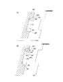
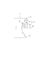
- FIG. 1 is an enlarged view of an optical surface S1 of an objective lens molded from a mold processed by a conventional technique.
- This objective lens has a diffractive structure D having a plurality of annular projections having an inner wall IW and an outer wall OW, and the inner wall IW and the outer wall OW extend in a direction facing each other. ing.
- the parallel light beam L is incident on the objective lens
- the light beam incident on the optical surface other than the inner wall IW and the outer wall OW is used for condensing the optical disk, but is incident on the inner wall IW and the outer wall OW.
- the luminous flux (indicated by hatching) is rarely used for light collection. This is called the shadow effect, and is a factor in reducing efficiency.
- the decrease in efficiency due to the shadow effect is generally negligible with DVD and CD objective lenses, but with a BD / DVD / CD compatible objective lens, etc. It can be said that it is necessary to increase the actual efficiency.
- the inventors focused on the outer wall OW. If the outer wall OW is formed parallel to the optical axis as indicated by the dotted line, it is possible to suppress the parallel light beam from entering the outer wall OW, and accordingly, it is possible to suppress the efficiency reduction of the objective lens.
- the mold is processed so that the outer wall OW is inclined.
- a mold capable of forming an objective lens close to the design state by rotating ( ⁇ ) the axis BX of the rake face of the tool BT within a plane orthogonal to the rotation axis RO.
- a tool having a rake face BT3 that is at least partially contoured from a first edge BT1 and a second edge BT2 extending in a direction intersecting the first edge BT1.
- the BT is formed so that the first edge BT1 is farther from the rotation axis RO of the mold material WK than the second edge BT2, and the tip of the rake face BT3 is separated from the rotation axis RO. Since the material WK is set while being inclined with respect to the rotation axis of the mold material WK, the first peripheral surface OW ′ cut by the first edge portion BT1 can be made substantially parallel to the rotation axis. If the optical element is transferred using such a mold, the outer OIW (see FIG. 1) of the annular groove transferred by the first peripheral surface can be made parallel to the optical axis. Thereby, the efficiency of the optical element can be increased.
- the die machining method according to the first aspect of the invention, wherein the tool axis is set to be inclined with respect to the rotation axis from the outer periphery to the center of the workpiece in the workpiece. It is characterized by cutting with. This saves the labor of setting the tool.
- the mold machining method according to claim 3 is characterized in that an inclination angle of the axis line of the tool with respect to the rotation axis line is changed during cutting of the workpiece portion of the material.
- an inclination angle of the axis line of the tool with respect to the rotation axis line is changed during cutting of the workpiece portion of the material.
- a die machining method according to the third aspect of the invention, wherein the axis of the tool is set in parallel to the rotation axis from the outer periphery to the intermediate portion of the workpiece in the workpiece. Cutting is performed in a state in which the axis of the tool is set to be inclined with respect to the rotation axis from the intermediate portion to the center.
- the effect of the present invention can be expected.
- a die processing method according to any one of the first to fourth aspects, wherein at least a part of the peripheral wall of the concave annular zone structure is at least far from the optical axis of the annular zone structure.
- the peripheral wall on the side is parallel to the optical axis. Since this structure can reduce the effect of shadows due to the outer wall of the annular groove as described above, it is preferable because the efficiency of the optical element can be increased.
- a peripheral wall near the optical axis of the annular structure is inclined with respect to the optical axis.
- the peripheral wall close to the optical axis for example, the inner wall IW in FIG. 1, even if the inner wall is made parallel to the optical axis, the effect of shadow is inevitable. Therefore, the necessity of making the inner wall IW parallel to the optical axis is lower than that of the outer wall OW. Therefore, it is preferable that the inner wall IW is kept inclined with respect to the optical axis, so that a greater degree of freedom can be secured for setting the inclination angle of the tool axis with respect to the rotation axis.
- the tilt angle of the tool axis with respect to the rotation axis is set so that the outer wall is parallel to the optical axis, and it is possible to cut all steps with the tilt angle. Operation becomes easier.
- the mold processing method according to claim 7 is the invention according to any one of claims 1 to 6, wherein the rake face of the tool includes the first edge end and the second edge end.
- a third edge portion having an arc shape connecting the first and second portions, and a radius of the third edge portion is 0.1 to 0.5 ⁇ m.
- the mold machining method according to claim 8 is the invention according to any one of claims 1 to 7, wherein an inclination angle of the axis of the tool with respect to the rotation axis is the first edge and the second. It is characterized in that it is about half the apex angle formed by the edge of each other. With this configuration, since the first edge is parallel to the rotation axis, the step cut at the first edge is easily parallel to the rotation axis.
- an apex angle formed by the first edge portion and the second edge portion is 20-30. It is characterized by °. As a result, interference with the fine shape is reduced, and processing closer to the design shape becomes possible.
- a method for machining a mold according to a tenth aspect is the invention according to the ninth aspect, wherein an inclination angle of the axis of the tool with respect to the rotation axis is 8 to 18 °.
- the mold according to claim 11 is processed by the processing method according to any one of claims 1 to 5.
- the optical element according to claim 12 emits a first light source that emits a first light beam with a first wavelength ⁇ 1 (390 nm ⁇ ⁇ 1 ⁇ 415 nm) and a second light beam with a second wavelength ⁇ 2 (630 nm ⁇ ⁇ 2 ⁇ 670 nm). And a third light source that emits a third light beam having a third wavelength ⁇ 3 (760 nm ⁇ ⁇ 3 ⁇ 820 nm), and a protective substrate having a thickness t1 using the first light beam.
- the third light beam is condensed so that the second light flux passing through the central region is condensed so that information can be recorded and / or reproduced on the information recording surface of the DVD, and the third light beam passing through the central region.
- the light beam is condensed so that information can be recorded and / or reproduced on the information recording surface of the CD, and the first light beam passing through the intermediate area is recorded and / or recorded on the information recording surface of the BD.
- the second light flux that is condensed so that it can be reproduced and passes through the intermediate area is condensed so that information can be recorded and / or reproduced on the information recording surface of the DVD, and the second light flux that passes through the intermediate area
- the third beam is recorded on the information recording surface of the CD.
- the first luminous flux that passes through the peripheral area without being condensed so that it can be reproduced is condensed so that information can be recorded and / or reproduced on the information recording surface of the BD, and the peripheral area
- the second light flux that passes through the peripheral area is not condensed so that information can be recorded and / or reproduced on the information recording surface of the DVD, and the third light flux that passes through the peripheral area is focused on the information recording surface of the CD.
- the central region includes a first optical path difference providing structure, and the first optical path difference providing structure includes a first basic structure having a blazed structure.
- the second foundation structure having a blazed structure is superimposed on each other in the opposite direction, the step of the first foundation structure is directed in the direction opposite to the optical axis, and the step of the second foundation structure is a light Facing the direction of the axis and passing through the first foundation structure
- the first order diffracted light amount of the first light beam is larger than any other order diffracted light amount
- the first order diffracted light amount of the second light beam that has passed through the first basic structure is larger than any other order diffracted light amount.
- the first-order diffracted light amount of the third light beam that has passed through the first basic structure is larger than any other order of diffracted light amount
- the second-order diffracted light amount of the first light beam that has passed through the second basic structure is larger than any other order of diffracted light amount
- the diffracted light quantity is larger than any other order diffracted light quantity
- the first order diffracted light quantity of the second light flux that has passed through the second basic structure is larger than any other order diffracted light quantity
- the first-order diffracted light amount of the third light flux that has passed through the structure is larger than any other order diffracted light amount
- the first optical path difference providing structure has peripheral walls that extend substantially in the optical axis direction and face each other. Has an annular ridge, and at least The peripheral wall on the side farther from the optical axis of the annular convex part is parallel to the optical axis, and the peripheral wall on the side close to the optical axis of the annular convex part is on the annular convex part with respect to the optical axis. It is characterized by tilting away from the optical axis toward the tip.
- the first optical path difference providing structure is a structure in which a first basic structure having a blazed structure and a second basic structure having a blazed structure are overlapped in opposite directions, and the first basic structure is The first-order diffracted light amount of the first light beam that has passed through one basic structure is made larger than any other order of diffracted light amount, and the first-order diffracted light amount of the second light beam that has passed through the first basic structure is set to any other order The first order diffracted light amount of the third light flux that has passed through the first basic structure is made larger than any other order diffracted light amount (hereinafter also referred to as “1/1/1”).
- the second basic structure has a second-order diffracted light amount of the first light beam that has passed through the second basic structure larger than any other order of diffracted light amount, and has passed through the second basic structure.
- Diffraction of any other order for the first-order diffracted light quantity of the light beam A diffractive structure that is larger than the amount of light and that makes the first-order diffracted light amount of the third light beam that has passed through the second basic structure larger than any other order diffracted light amount (hereinafter also referred to as “2/1/1”). It is.
- the first optical path difference is given.
- the step of the structure can be lowered. If the level difference of the optical path difference providing structure can be reduced, the loss of efficiency due to manufacturing errors can be reduced, so that it is possible to obtain an optical element with even higher light utilization efficiency.
- the level difference between the first basic structure having the diffraction structure of “1/1/1” is light.
- the step of the second foundation structure having the diffractive structure of “2/1/1” is directed in the direction opposite to the axis, and is directed in the direction of the optical axis.
- the step of the first basic structure having the diffraction structure of “1/1/1” is directed in the direction of the optical axis
- the step of the second basic structure having the diffraction structure of “2/1/1” is
- the number of peripheral walls on the side farther from the optical axis of the annular zone convex portion of the first optical path difference providing structure is larger than when facing in the direction opposite to the optical axis. Therefore, by making the peripheral wall far from the optical axis of the annular convex part parallel to the optical axis, the loss of efficiency due to the shadow effect is greatly reduced, and ideal light utilization efficiency close to the design value is obtained.
- the present invention becomes more useful.
- the optical element according to claim 13 is the optical element according to claim 12, wherein the annular groove has an optical path difference providing structure.
- the optical element according to claim 14 is characterized in that, in the invention according to claim 12 or 13, the optical element is an objective lens.
- the optical pickup device using the optical element according to the present invention has at least three light sources: a first light source, a second light source, and a third light source. Furthermore, the optical pickup device of the present invention condenses the first light beam on the information recording surface of the BD, condenses the second light beam on the information recording surface of the DVD, and focuses the third light beam on the information recording surface of the CD. A condensing optical system for condensing the light.
- the optical pickup device of the present invention includes a light receiving element that receives a reflected light beam from an information recording surface of a BD, DVD, or CD.
- the BD has a protective substrate having a thickness t1 and an information recording surface.
- the DVD has a protective substrate having a thickness t2 (t1 ⁇ t2) and an information recording surface.
- the CD has a protective substrate having a thickness of t3 (t2 ⁇ t3) and an information recording surface.
- the BD, DVD, or CD may be a multi-layer optical disc having a plurality of information recording surfaces.
- BD means that information is recorded / reproduced by a light beam having a wavelength of about 390 to 415 nm and an objective lens having an NA of about 0.8 to 0.9, and the thickness of the protective substrate is 0.05 to 0.00 mm.
- It is a generic term for a BD series optical disc of about 125 mm, and includes a BD having only a single information recording layer, a BD having two or more information recording layers, and the like.
- DVD is a general term for DVD series optical discs in which information is recorded / reproduced by an objective lens having an NA of about 0.60 to 0.67 and the thickness of the protective substrate is about 0.6 mm.
- CD is a general term for CD series optical discs in which information is recorded / reproduced by an objective lens having an NA of about 0.45 to 0.51 and the thickness of the protective substrate is about 1.2 mm.
- the recording density the recording density of BD is the highest, followed by the order of DVD and CD.
- the thickness of the protective substrate referred to here is the thickness of the protective substrate provided on the surface of the optical disk. That is, the thickness of the protective substrate from the optical disc surface to the information recording surface closest to the surface. 0.050 mm ⁇ t1 ⁇ 0.125 mm (1) 0.5mm ⁇ t2 ⁇ 0.7mm (2) 1.0mm ⁇ t3 ⁇ 1.3mm (3)
- a first light source for BD that emits a light beam with a first wavelength ⁇ 1
- a second light source for DVD that emits a light beam with a second wavelength ⁇ 2
- a first light source for CD that emits a light beam with a third wavelength ⁇ 3.
- the three light sources are preferably laser light sources.
- the laser light source a semiconductor laser, a silicon laser, or the like can be preferably used.
- the wavelength ⁇ 3 ( ⁇ 3> ⁇ 2) preferably satisfies the following conditional expressions (4) and (5). 1.5 ⁇ ⁇ 1 ⁇ 2 ⁇ 1.7 ⁇ ⁇ 1 (4) 1.8 ⁇ ⁇ 1 ⁇ 3 ⁇ 2.0 ⁇ ⁇ 1 (5)
- the first wavelength ⁇ 1 of the first light source is preferably 350 nm to 440 nm, more preferably 390 nm to 415 nm
- the second wavelength ⁇ 2 of the second light source is preferably 570 nm to 680 nm, more preferably.
- the third wavelength ⁇ 3 of the third light source is preferably 750 nm or more and 880 nm or less, more preferably 760 nm or more and 820 nm or less.
- the condensing optical system of the optical pickup device has an objective lens.
- the condensing optical system preferably has a coupling lens such as a collimator in addition to the objective lens.
- the coupling lens is a single lens or a lens group that is disposed between the objective lens and the light source and changes the divergence angle of the light beam.
- the collimator is a type of coupling lens, and is a lens that emits light incident on the collimator as parallel light. These are all optical elements.
- the objective lens refers to an optical system that is disposed at a position facing the optical disk in the optical pickup device and has a function of condensing the light beam emitted from the light source onto the information recording surface of the optical disk.
- the objective lens is preferably a single lens or a plurality of plastic or glass lenses.
- a convex lens is preferable.
- the objective lens preferably has a refractive surface that is aspheric.
- the base surface on which the optical path difference providing structure is provided is preferably an aspherical surface.
- a resin is used as the material of the optical element
- a cycloolefin resin is preferably used.
- ZEONEX manufactured by Nippon Zeon Co., Ltd.
- APEL manufactured by Mitsui Chemicals, Inc.
- ARTON A preferred example is ARTON.
- the Abbe number of the material constituting the objective lens is preferably 50 or more.
- At least one optical surface of the three-compatible objective lens has at least a central region, an intermediate region around the central region, and a peripheral region around the intermediate region.
- the central region is preferably a region including the optical axis of the three-compatible objective lens.
- a minute region including the optical axis is used as an unused region or a special purpose region, and the surrounding region is a central region (also referred to as a central region).
- the central region, the intermediate region, and the peripheral region are preferably provided on the same optical surface. As shown in FIG. 3, it is preferable that the central region CN, the intermediate region MD, and the peripheral region OT are provided concentrically around the optical axis on the same optical surface.
- a three-wavelength shared first optical path difference providing structure is provided in the central area of the 3-compatible objective lens, and a two-wavelength shared second optical path difference providing structure is provided in the intermediate area.
- the peripheral region may be a refracting surface, or a third optical path difference providing structure may be provided in the peripheral region.
- the central region, the intermediate region, and the peripheral region are preferably adjacent to each other, but there may be a slight gap between them.
- the central area of the 3 compatible objective lens can be said to be a preferred BD / DVD / CD shared area when used for recording / reproducing BD, DVD and CD. That is, the 3-compatible objective lens condenses the first light flux that passes through the central area so that information can be recorded / reproduced on the information recording surface of the BD, and the second light flux that passes through the central area becomes the DVD. It is preferable that the light is condensed on the information recording surface so that information can be recorded / reproduced, and the third light flux passing through the central region is condensed so that information can be recorded / reproduced on the information recording surface of the CD.
- the first optical path difference providing structure provided in the central region has the BD protective substrate thickness t1 and the DVD protective substrate thickness with respect to the first and second light fluxes passing through the first optical path difference providing structure. It is preferable to correct spherical aberration generated due to the difference in thickness t2 / spherical aberration generated due to the difference in wavelength between the first light beam and the second light beam. Further, the first optical path difference providing structure is different from the thickness t1 of the BD protective substrate and the thickness t3 of the CD protective substrate with respect to the first and third light fluxes that have passed through the first optical path difference providing structure. It is preferable to correct the spherical aberration caused by the difference in the wavelength of the first light beam and the third light beam.
- the intermediate area of the 3 compatible objective lens is used for BD and DVD recording / reproduction, and can be said to be a preferable BD / DVD common area when not used for CD recording / reproduction. That is, the 3-compatible objective lens condenses the first light flux passing through the intermediate area so that information can be recorded / reproduced on the information recording surface of the BD, and the second light flux passing through the intermediate area is converted into the DVD. It is preferable to collect light so that information can be recorded / reproduced on the information recording surface. On the other hand, it is preferable that the third light flux passing through the intermediate region is not condensed so that information can be recorded / reproduced on the information recording surface of the CD.
- the third light flux that passes through the intermediate region of the three-compatible objective lens preferably forms a flare on the information recording surface of the CD.
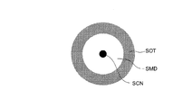
- the light amount density is changed in the order from the optical axis side (or the center of the spot) to the outside. It is preferable to have a high spot central portion SCN, a spot intermediate portion SMD whose light intensity density is lower than that of the spot central portion, and a spot peripheral portion SOT whose light intensity density is higher than that of the spot intermediate portion and lower than that of the spot central portion.
- the center portion of the spot is used for recording / reproducing information on the optical disc, and the middle portion of the spot and the peripheral portion of the spot are not used for recording / reproducing information on the optical disc.
- this spot peripheral part is called flare.
- the spot peripheral part may be called a flare. Good.
- the third light flux that has passed through the intermediate region of the three-compatible objective lens preferably forms a spot peripheral portion on the information recording surface of the CD.
- the peripheral area of the 3 compatible objective lens is used for BD recording / reproduction, and can be said to be a preferable BD-dedicated area when not used for DVD / CD recording / reproduction. That is, it is preferable that the three-compatible objective lens condenses the first light beam passing through the peripheral region so that information can be recorded / reproduced on the information recording surface of the BD. On the other hand, the second light flux that passes through the peripheral area is not condensed so that information can be recorded / reproduced on the information recording surface of the DVD, and the third light flux that passes through the peripheral area does not converge. It is preferable not to collect light so that information can be recorded / reproduced.
- the second light flux and the third light flux that pass through the peripheral area of the 3-compatible objective lens preferably form a flare on the information recording surface of DVD and CD. That is, it is preferable that the second light flux and the third light flux that have passed through the peripheral area of the three-compatible objective lens form a spot peripheral portion on the information recording surface of the DVD and CD.
- the first optical path difference providing structure is preferably provided in a region of 70% or more of the area of the central region of the three-compatible objective lens, and more preferably 90% or more. More preferably, the first optical path difference providing structure is provided on the entire surface of the central region.
- the second optical path difference providing structure is preferably provided in a region of 70% or more of the area of the intermediate region of the three-compatible objective lens, and more preferably 90% or more. More preferably, the second optical path difference providing structure is provided on the entire surface of the intermediate region.
- the third optical path difference providing structure is preferably provided in an area of 70% or more of the area of the peripheral area of the 3-compatible objective lens, and 90% or more is provided. More preferred. More preferably, the third optical path difference providing structure is provided on the entire surface of the peripheral region.
- the optical path difference providing structure referred to in this specification is a general term for a structure that adds an optical path difference to an incident light beam, and has an annular groove.
- the optical path difference providing structure also includes a phase difference providing structure for providing a phase difference.
- the phase difference providing structure includes a diffractive structure.
- the optical path difference providing structure of the present invention is preferably a diffractive structure.
- the optical path difference providing structure has a step, preferably a plurality of steps. This step adds an optical path difference and / or phase difference to the incident light flux.
- the optical path difference added by the optical path difference providing structure may be an integer multiple of the wavelength of the incident light beam or a non-integer multiple of the wavelength of the incident light beam.
- the steps may be arranged with a periodic interval in the direction perpendicular to the optical axis, or may be arranged with a non-periodic interval in the direction perpendicular to the optical axis.
- the objective lens provided with the optical path difference providing structure is a single aspherical lens
- the incident angle of the light flux to the objective lens differs depending on the height from the optical axis.
- Each will be slightly different.
- the objective lens is a single-lens aspherical convex lens, even if it is an optical path difference providing structure that provides the same optical path difference, generally the distance from the optical axis tends to increase.
- the diffractive structure referred to in this specification is a general term for structures that have a step and have a function of converging or diverging a light beam by diffraction.
- a plurality of unit shapes are arranged around the optical axis, and a light beam is incident on each unit shape, and the wavefront of the transmitted light is shifted between adjacent annular zones, resulting in new It includes a structure that converges or diverges light by forming a simple wavefront.
- the diffractive structure preferably has a plurality of steps, and the steps may be arranged with a periodic interval in the direction perpendicular to the optical axis, or may be arranged with a non-periodic interval in the direction perpendicular to the optical axis.
- the objective lens provided with the diffractive structure is a single aspherical lens
- the incident angle of the light beam to the objective lens differs depending on the height from the optical axis, so the step amount of the diffractive structure is slightly different for each annular zone. It will be.
- the objective lens is a single aspherical convex lens, even if it is a diffractive structure that generates diffracted light of the same diffraction order, generally, the distance from the optical axis tends to increase.
- the optical path difference providing structure has a plurality of concentric annular zones with the optical axis as the center.
- the optical path difference providing structure can generally have various cross-sectional shapes (cross-sectional shapes on the plane including the optical axis), and the cross-sectional shapes including the optical axis are roughly classified into a blazed structure and a staircase structure.
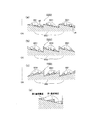
- the blaze-type structure means that the cross-sectional shape including the optical axis of the optical element having the optical path difference providing structure is a sawtooth shape.
- the upper side is the light source side and the lower side is the optical disk side, and the optical path difference providing structure is formed on a plane as a mother aspherical surface.
- the length in the direction perpendicular to the optical axis of one blaze unit is called a pitch P.
- the length of the step in the direction parallel to the optical axis of the blaze is referred to as a step amount B.
- FIG. 5A In such a single blazed structure, there are no peripheral walls facing each other.
- the staircase structure has a cross-sectional shape including an optical axis of an optical element having an optical path difference providing structure (referred to as a staircase unit). ).
- V level means a ring-shaped surface (hereinafter also referred to as a terrace surface) corresponding to (or facing) the vertical direction of the optical axis in one step unit of the step structure. In other words, it is divided by V steps and divided into V ring zones.
- a three-level or higher staircase structure has a small step and a large step.
- the optical path difference providing structure illustrated in FIG. 5C is referred to as a five-level step structure
- the optical path difference providing structure illustrated in FIG. 5D is referred to as a two-level step structure (also referred to as a binary structure). .
- the optical path difference providing structure is preferably a structure in which a certain unit shape is periodically repeated.
- the unit shape is periodically repeated here naturally includes shapes in which the same shape is repeated in the same cycle.
- the unit shape that is one unit of the cycle has regularity, and the shape in which the cycle gradually increases or decreases gradually is also included in the “unit shape is periodically repeated”.
- first optical path difference providing structure and the second optical path difference providing structure may be provided on different optical surfaces of the objective lens, but are preferably provided on the same optical surface.
- the first optical path difference providing structure, the second optical path difference providing structure, and the third optical path difference providing structure are preferably provided on the light source side surface of the objective lens rather than the surface of the objective lens on the optical disk side.
- the first optical path difference providing structure, the second optical path difference providing structure, and the third optical path difference providing structure are preferably provided on the optical surface having the smaller absolute value of the radius of curvature of the objective lens. It is also conceivable to provide the first basic structure and the second basic structure on different optical surfaces without overlapping. Similarly, the third basic structure and the fourth basic structure may be provided on different optical surfaces without overlapping.
- the optical path difference providing structure may be a structure in which a plurality of basic structures (for example, the first basic structure and the second basic structure in FIG. 6D) are overlapped.
- FIG. 6 shows the first optical path difference providing structure ODS1 as a flat plate for convenience, it may be provided on a single aspherical convex lens.
- the second-order diffracted light quantity of the first light beam that has passed through the second basic structure is made larger than any other order of diffracted light quantity, and the first-order diffracted light quantity of the second light beam that has passed through the second basic structure is set to any other order.
- the first-order diffracted light amount of the third light beam that has passed through the second basic structure is larger than any other order diffracted light amount (“2/1/1”).
- the first-order diffracted light quantity of the first light beam that has passed through the first basic structure is made larger than the diffracted light quantity of any other order in the two basic structure BS2, and the first-order diffraction of the second light beam that has passed through the first basic structure.
- the light quantity is made larger than any other order diffracted light quantity
- the first order diffracted light quantity of the third light flux that has passed through the first basic structure is made larger than any other order diffracted light quantity (“1/1/1”). )
- An example in which the first basic structure BS1 that is a diffractive structure is overlaid. . In FIG.
- the step of the second foundation structure BS2 faces the direction of the optical axis OA
- the step of the first foundation structure BS1 faces the direction opposite to the optical axis OA. Furthermore, it can be seen that the positions of all the steps of the second foundation structure BS2 are aligned with the positions of the steps of the first foundation structure BS1.
- the step of the second foundation structure BS2 faces the direction of the optical axis OA
- the step of the first foundation structure BS1 also faces the direction of the optical axis OA. Furthermore, it can be seen that the positions of all the steps of the second foundation structure BS2 are aligned with the positions of the steps of the first foundation structure BS1.
- step difference of 1st foundation structure BS1 has faced the direction opposite to optical axis OA
- step difference of 2nd foundation structure BS2 has also faced the direction opposite to optical axis OA.
- the positions of all the steps of the second foundation structure BS2 are aligned with the positions of the steps of the first foundation structure BS1.
- FIGS. 5 (c), (d) This refers to the structure shown in FIG.
- NA1 is preferably 0.75 or more and 0.9 or less, and more preferably 0.8 or more and 0.9 or less.
- NA1 is preferably 0.85.
- NA2 is preferably 0.55 or more and 0.7 or less.
- NA2 is preferably 0.60 or 0.65.
- NA3 is preferably 0.4 or more and 0.55 or less.
- NA3 is preferably 0.45 or 0.53.
- the boundary between the central region and the intermediate region of the objective lens is 0.9 ⁇ NA 3 or more and 1.2 ⁇ NA 3 or less (more preferably 0.95 ⁇ NA 3 or more, 1.15 ⁇ NA 3) when the third light beam is used. It is preferably formed in a portion corresponding to the following range. More preferably, the boundary between the central region and the intermediate region of the objective lens is formed in a portion corresponding to NA3. Further, the boundary between the intermediate region and the peripheral region of the objective lens is 0.9 ⁇ NA 2 or more and 1.2 ⁇ NA 2 or less (more preferably 0.95 ⁇ NA 2 or more, 1.15) when the second light flux is used. -It is preferably formed in a portion corresponding to the range of NA2 or less. More preferably, the boundary between the intermediate region and the peripheral region of the objective lens is formed in a portion corresponding to NA2.
- the spherical aberration has at least one discontinuous portion.
- the discontinuous portion has a range of 0.9 ⁇ NA 3 or more and 1.2 ⁇ NA 3 or less (more preferably 0.95 ⁇ NA 3 or more and 1.15 ⁇ NA 3 or less) when the third light flux is used. It is preferable that it exists in.
- the present invention is particularly suitable for an objective lens used in a thin slim type optical pickup device. Since the objective lens used in the slim type optical pickup device inevitably has a small diameter, the pitch of the annular zone is also reduced, making it difficult to process. For this reason, the effects of the present invention are more conspicuous, and the effect of the present invention with less loss of light utilization efficiency becomes more remarkable.
- the objective lens used in the slim type optical pickup device preferably has a diameter in the direction perpendicular to the optical axis of the entire objective lens including the flange and the optical surface in the range of 1.45 mm to 4.05 mm. More preferably, it is 2.95 mm or more and 4.05 mm or less. Moreover, it is preferable that the minimum value of the pitch of the optical path difference providing structure in the direction perpendicular to the optical axis is 2.5 ⁇ m or more and 10 ⁇ m or less. The maximum pitch value is preferably 110 ⁇ m or less. Furthermore, it is preferable that the total number of zones of the optical path difference providing structure in the entire objective lens is 150 or more and 250 or less.
- the tool used in the present invention includes a rake face that is at least partially contoured from a first edge and a second edge extending in a direction intersecting the first edge.
- the first edge is farther from the rotation axis of the mold material than the second edge.
- the first edge and the second edge may be directly connected with the tool axis as a boundary, or may be connected via a third edge that crosses the tool axis.
- the first edge and the second edge are each preferably straight, but a part of the first edge may be arcuate.
- a mold for molding an optical element such as an objective lens compatible with three types of optical disks of BD / DVD / CD, which can suppress a decrease in efficiency of the optical element as much as possible.
- Methods, processed molds, and optical elements transferred from the molds can be provided.
- FIG. 1 It is a figure which shows a diamond tool
- (a) is a perspective view which shows the cutting edge of the diamond tool used with the processing method of the metal mold
- (b) is an enlarged view which shows the front-end
- a BD / DVD / CD compatible objective lens is designed using optical design software such as codeV. Then, the mold is processed based on the design result.
- FIG.7 (a) is a perspective view which shows the cutting edge of the diamond tool used with the processing method of the metal mold
- FIG.7 (b) is an enlarged view which shows the front-end
- the cutting edge 3 of the diamond tool is brazed to the shank S as shown in the figure, and has a rake face 3a that faces the rotational direction of the mold to be cut.
- the tip of the rake face 3a connects the edge 3b as the first edge and the edge 3c as the second edge with the end A of the edge 3b and the end B of the edge 3c. It is contoured from the arc part 3d which is the third edge.
- the scissor angle (vertical angle) between the first edge 3b and the second edge 3c is preferably 20 to 30 ° (preferably 29 ° or less).
- the bisector of the first edge 3b and the second edge 3c is defined as the axis BX of the tool 3.
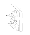
- FIG. 8 is a perspective view of an XZB-axis ultra-precision lathe used for mold machining.
- FIG. 9 is an enlarged cross-sectional view when cutting a mold using a diamond tool.
- a rotation drive mechanism 9 is provided on a Z-axis stage 5 that is movable in the Z-axis direction with respect to the surface plate 10, and the rotation drive mechanism 9 rotates the mold material 1 to be cut. It is designed to rotate around the axis AX.
- a B-axis stage 11 that can rotate about the B-axis is provided on the surface plate 10, and an X-axis stage 6 that is movable in the X direction is provided on the B-axis stage 11.
- the optical transfer surface can be processed by moving it relative to the material 1.
- the mold material 1 uses an iron-based base material, and after roughing the required shape with respect to the cutting surface, electroless nickel plating is applied as a processing layer to a thickness of about 50 ⁇ m. .
- the shape required for the optical surface (surface to be processed) 1a of the mold material 1 is the diffractive optical surface shape of the BD / DVD / CD compatible plastic objective lens.
- the mold material 1 is rotated at, for example, 1000 revolutions per minute, and the X-axis stage 6 and the Z-axis stage 5 are controlled by program control so that the tip of the diamond tool 3 is indicated by the arrow in FIG.
- the translational movement is performed from the outer peripheral side toward the central portion at a moving speed of 0.1 mm per minute so as to obtain a desired diffractive optical surface shape.
- the bisector BX (see FIG. 7B) of the apex angle of the diamond tool 3 is tilted with respect to the rotation axis AX of the mold material 1 and the outer periphery. Cutting from center to center.
- the inclination angle of the bisector BX of the apex angle with respect to the rotation axis is about half of the apex angle. In this case, the angle is 8 ° to 18 °.
- the first edge 3b (however, depending on the tilt angle, cutting may be performed at the third edge 3d, but in this case, cutting is performed on the side far from the rotation axis across the tool axis.
- the peripheral surface (first peripheral surface) closer to the optical axis in the ring-shaped convex portion 1d (first peripheral surface) (in the concave portion, the peripheral surface away from the optical axis) 1b can be formed parallel to the rotation axis AX.
- the objective lens when the objective lens is molded using a die cut by such processing, the objective lens whose peripheral wall (corresponding to the outer wall OW in FIG. 1) on the side far from the optical axis of the annular convex portion is parallel to the optical axis. Can be formed.
- the second edge 3c forms a circumferential surface (second circumferential surface) 1c far from the optical axis in the annular projection 1d (a circumferential surface closer to the optical axis in the concave portion) 1c. it can. That is, when the objective lens is formed using a die cut by such processing, the peripheral wall (corresponding to the inner wall IW in FIG. 1) on the side closer to the optical axis of the annular convex portion is annular convex with respect to the optical axis. It is possible to form an objective lens that is inclined away from the optical axis toward the tip of the part.
- the first edge 3b does not have to be strictly parallel to the rotation axis AX.
- the diamond tool 3 is closer to the optical axis by relative movement in the Z direction. This is because the peripheral surface 1b on the side can be formed parallel to the rotation axis AX.
- the bisector BX of the apex angle of the diamond tool 3 is set to the rotational axis AX of the mold material 1 from the outer periphery to the middle part of the machining surface 1a of the mold material 1. Cutting is performed in a parallel state, and then the diamond tool 3 is rotated about the B axis in FIG. 8. From the middle part to the center, the bisector BX of the apex angle of the diamond tool 3 is set as a mold. Cutting can also be performed by changing the angle to a state in which the material 1 is tilted with respect to the rotation axis AX.
- the first edge 3b can form the circumferential surface 1b on the side close to the optical axis of the ring-shaped convex portion 1d in a range from the intermediate portion to the center in parallel to the rotation axis AX. That is, when an objective lens is molded using a die cut by such processing, an objective lens in which the peripheral wall near the optical axis of the annular groove is parallel to the optical axis in the range from the intermediate portion to the center can be formed. .
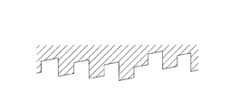
- FIGS. 10 and 11 show an enlarged cross-sectional shape of a part of a mold to be processed, and the shape of the mold is indicated by hatching.
- the inventors divided the bisector of the apex angle of the diamond tool 3 into the bisector of the apex angle of the diamond tool 3 and the comparative mold that does not incline with respect to the rotation axis AX of the mold material 1.
- Each of the molds of the example in which the line BX was inclined with respect to the rotation axis AX of the mold material 1 was manufactured, and an objective lens having a compatible diffraction structure was molded by both molds.
- diffraction efficiency of the objective lens molded from the comparative mold was measured, diffraction efficiency when using BD: 74.1%, diffraction efficiency when using DVD: 56.4%, diffraction efficiency when using CD: 52 It was 1%.
- the optical element is not limited to an objective lens.
Landscapes
- Engineering & Computer Science (AREA)
- Mechanical Engineering (AREA)
- Physics & Mathematics (AREA)
- Optics & Photonics (AREA)
- Optical Head (AREA)
- Moulds For Moulding Plastics Or The Like (AREA)
- Turning (AREA)
- Diffracting Gratings Or Hologram Optical Elements (AREA)
Abstract
La présente invention se rapporte à un procédé permettant d'usiner un moule destiné à usiner un élément optique tel qu'une lentille d'objectif avec une compatibilité pour trois types de disques optiques tels que les disques BD/DVD/CD, ledit moule pouvant réduire à un minimum la diminution de l'efficacité de l'élément optique. La présente invention se rapporte également à un moule usiné et à un élément optique transcrit à partir du moule. Par découpe d'un matériau au moyen d'un outil pourvu d'une face de découpe dont au moins une partie est entourée par un premier bord linéaire et un second bord qui s'étend dans la direction qui coupe le premier bord, le premier bord étant façonné de sorte à être incliné par rapport à un axe de rotation, une première face périphérique coupée par le premier bord est parallèle à l'axe de rotation. Par conséquent, si un élément optique est transcrit à l'aide d'un moule ainsi formé, la première face périphérique peut être rendue parallèle à l'axe optique.
Priority Applications (3)
| Application Number | Priority Date | Filing Date | Title |
|---|---|---|---|
| CN201280016313.5A CN103459114B (zh) | 2011-03-31 | 2012-03-28 | 模具的加工方法、模具以及光拾取装置用的光学元件 |
| PH1/2013/501989A PH12013501989A1 (en) | 2011-03-31 | 2012-03-28 | Method for machining mold, mold, and optical element for optical pickup device |
| JP2012540200A JPWO2012133531A1 (ja) | 2011-03-31 | 2012-03-28 | 金型の加工方法 |
Applications Claiming Priority (2)
| Application Number | Priority Date | Filing Date | Title |
|---|---|---|---|
| JP2011077110 | 2011-03-31 | ||
| JP2011-077110 | 2011-03-31 |
Publications (1)
| Publication Number | Publication Date |
|---|---|
| WO2012133531A1 true WO2012133531A1 (fr) | 2012-10-04 |
Family
ID=46931240
Family Applications (1)
| Application Number | Title | Priority Date | Filing Date |
|---|---|---|---|
| PCT/JP2012/058143 Ceased WO2012133531A1 (fr) | 2011-03-31 | 2012-03-28 | Procédé permettant d'usiner un moule, moule et élément optique pour un dispositif de lecture optique |
Country Status (4)
| Country | Link |
|---|---|
| JP (2) | JPWO2012133531A1 (fr) |
| CN (1) | CN103459114B (fr) |
| PH (1) | PH12013501989A1 (fr) |
| WO (1) | WO2012133531A1 (fr) |
Families Citing this family (1)
| Publication number | Priority date | Publication date | Assignee | Title |
|---|---|---|---|---|
| HUE038956T2 (hu) * | 2015-10-02 | 2018-12-28 | Rayner Intraocular Lenses Ltd | Multifokális lencse |
Citations (4)
| Publication number | Priority date | Publication date | Assignee | Title |
|---|---|---|---|---|
| JPS62102901A (ja) * | 1985-10-28 | 1987-05-13 | Toshiba Corp | 光学部品製作方法 |
| JPH1110401A (ja) * | 1997-04-21 | 1999-01-19 | Asahi Optical Co Ltd | 輪帯レンズ成形用金型の加工方法及びそのバイト |
| JP2001129702A (ja) * | 1999-11-05 | 2001-05-15 | Canon Inc | 成形用金型部材の加工方法、成形用金型部材の加工装置、及び、表面に微細光学機能形状を形成した光学部品、並びに、光学素子の保持部材 |
| JP2003062707A (ja) * | 2001-08-22 | 2003-03-05 | Konica Corp | ダイヤモンド工具、加工方法、光学素子成形用金型及び合成樹脂製光学素子 |
Family Cites Families (4)
| Publication number | Priority date | Publication date | Assignee | Title |
|---|---|---|---|---|
| JP3963750B2 (ja) * | 2002-03-25 | 2007-08-22 | 日本電産サンキョー株式会社 | 曲面切削加工方法 |
| JP3880474B2 (ja) * | 2002-07-11 | 2007-02-14 | キヤノン株式会社 | 金型の加工方法 |
| JP2005096064A (ja) * | 2003-09-02 | 2005-04-14 | Japan Science & Technology Agency | 軸対称回折曲面の切削加工方法及びそれによって作製される物品 |
| WO2009128313A1 (fr) * | 2008-04-18 | 2009-10-22 | コニカミノルタオプト株式会社 | Procédé pour traiter une matrice pour élément optique, matrice de moulage et élément optique |
-
2012
- 2012-03-28 WO PCT/JP2012/058143 patent/WO2012133531A1/fr not_active Ceased
- 2012-03-28 JP JP2012540200A patent/JPWO2012133531A1/ja active Pending
- 2012-03-28 PH PH1/2013/501989A patent/PH12013501989A1/en unknown
- 2012-03-28 CN CN201280016313.5A patent/CN103459114B/zh not_active Expired - Fee Related
- 2012-09-12 JP JP2012200134A patent/JP5310918B2/ja active Active
Patent Citations (4)
| Publication number | Priority date | Publication date | Assignee | Title |
|---|---|---|---|---|
| JPS62102901A (ja) * | 1985-10-28 | 1987-05-13 | Toshiba Corp | 光学部品製作方法 |
| JPH1110401A (ja) * | 1997-04-21 | 1999-01-19 | Asahi Optical Co Ltd | 輪帯レンズ成形用金型の加工方法及びそのバイト |
| JP2001129702A (ja) * | 1999-11-05 | 2001-05-15 | Canon Inc | 成形用金型部材の加工方法、成形用金型部材の加工装置、及び、表面に微細光学機能形状を形成した光学部品、並びに、光学素子の保持部材 |
| JP2003062707A (ja) * | 2001-08-22 | 2003-03-05 | Konica Corp | ダイヤモンド工具、加工方法、光学素子成形用金型及び合成樹脂製光学素子 |
Also Published As
| Publication number | Publication date |
|---|---|
| CN103459114B (zh) | 2016-09-28 |
| PH12013501989A1 (en) | 2013-11-25 |
| CN103459114A (zh) | 2013-12-18 |
| JP2013049272A (ja) | 2013-03-14 |
| JP5310918B2 (ja) | 2013-10-09 |
| JPWO2012133531A1 (ja) | 2014-07-28 |
Similar Documents
| Publication | Publication Date | Title |
|---|---|---|
| JP5370539B2 (ja) | 対物レンズ、光ピックアップ装置及び光情報記録再生装置 | |
| JP2011096350A (ja) | 光ピックアップ装置用の対物レンズ、光ピックアップ装置及び光情報記録再生装置 | |
| JP5740797B2 (ja) | 対物レンズ及び光ピックアップ装置 | |
| JP5310918B2 (ja) | 光ピックアップ装置用の光学素子 | |
| JP5602833B2 (ja) | 対物レンズ、光学ヘッド及び光ディスク装置 | |
| JP2007334952A (ja) | 光情報記録再生装置用対物レンズ | |
| JP6065347B2 (ja) | 対物レンズ及び光ピックアップ装置 | |
| JP2005310346A (ja) | 光学素子及び光ピックアップ装置 | |
| WO2011136096A1 (fr) | Lentille d'objectif pour capteur optique, capteur optique et dispositif optique d'enregistrement/lecture d'informations | |
| JPWO2011132691A1 (ja) | 光ピックアップ装置用の対物レンズ、光ピックアップ装置及び光情報記録再生装置 | |
| JP2010055732A (ja) | 対物光学素子及び光ピックアップ装置 | |
| JP5963120B2 (ja) | 対物レンズ、光ピックアップ装置及び光情報記録再生装置 | |
| WO2013005672A1 (fr) | Dispositif de tête optique | |
| JP5229657B2 (ja) | 光ピックアップ装置用の対物レンズ、光ピックアップ装置及び光情報記録再生装置 | |
| JP2013206515A (ja) | 光ピックアップ装置用の対物レンズ、光ピックアップ装置及び光情報記録再生装置 | |
| JPWO2013168692A1 (ja) | 対物レンズ及び光ピックアップ装置 | |
| JP2013206516A (ja) | 光ピックアップ装置用の対物レンズ、光ピックアップ装置及び光情報記録再生装置 | |
| JP2013157049A (ja) | 光ピックアップ装置用の対物レンズ、光ピックアップ装置及び光情報記録再生装置 | |
| WO2012090852A1 (fr) | Lentille de focalisation pour un dispositif de tête de lecture optique, dispositif de tête de lecture optique, et dispositif d'enregistrement/reproduction d'informations optiques | |
| JP2009283134A (ja) | 光学素子及び光ピックアップ装置 | |
| JP2014164791A (ja) | 光ピックアップ装置用の対物レンズ、光ピックアップ装置及び光情報記録再生装置 | |
| JP2013051002A (ja) | 光ピックアップ装置用の対物レンズ | |
| WO2013084558A1 (fr) | Lentille de focalisation pour dispositif de capteur optique, dispositif de capteur optique et dispositif d'enregistrement et de reproduction d'informations optique |
Legal Events
| Date | Code | Title | Description |
|---|---|---|---|
| ENP | Entry into the national phase |
Ref document number: 2012540200 Country of ref document: JP Kind code of ref document: A |
|
| 121 | Ep: the epo has been informed by wipo that ep was designated in this application |
Ref document number: 12765887 Country of ref document: EP Kind code of ref document: A1 |
|
| NENP | Non-entry into the national phase |
Ref country code: DE |
|
| 122 | Ep: pct application non-entry in european phase |
Ref document number: 12765887 Country of ref document: EP Kind code of ref document: A1 |