WO2012133593A1 - Dispositif de génération d'impulsions - Google Patents
Dispositif de génération d'impulsions Download PDFInfo
- Publication number
- WO2012133593A1 WO2012133593A1 PCT/JP2012/058262 JP2012058262W WO2012133593A1 WO 2012133593 A1 WO2012133593 A1 WO 2012133593A1 JP 2012058262 W JP2012058262 W JP 2012058262W WO 2012133593 A1 WO2012133593 A1 WO 2012133593A1
- Authority
- WO
- WIPO (PCT)
- Prior art keywords
- waveform
- pulse
- signal
- amplifier
- control unit
- Prior art date
- Legal status (The legal status is an assumption and is not a legal conclusion. Google has not performed a legal analysis and makes no representation as to the accuracy of the status listed.)
- Ceased
Links
Images


Classifications
-
- G—PHYSICS
- G01—MEASURING; TESTING
- G01S—RADIO DIRECTION-FINDING; RADIO NAVIGATION; DETERMINING DISTANCE OR VELOCITY BY USE OF RADIO WAVES; LOCATING OR PRESENCE-DETECTING BY USE OF THE REFLECTION OR RERADIATION OF RADIO WAVES; ANALOGOUS ARRANGEMENTS USING OTHER WAVES
- G01S7/00—Details of systems according to groups G01S13/00, G01S15/00, G01S17/00
- G01S7/02—Details of systems according to groups G01S13/00, G01S15/00, G01S17/00 of systems according to group G01S13/00
- G01S7/28—Details of pulse systems
- G01S7/282—Transmitters
-
- H—ELECTRICITY
- H03—ELECTRONIC CIRCUITRY
- H03K—PULSE TECHNIQUE
- H03K3/00—Circuits for generating electric pulses; Monostable, bistable or multistable circuits
- H03K3/01—Details
- H03K3/013—Modifications of generator to prevent operation by noise or interference
-
- H—ELECTRICITY
- H03—ELECTRONIC CIRCUITRY
- H03F—AMPLIFIERS
- H03F3/00—Amplifiers with only discharge tubes or only semiconductor devices as amplifying elements
- H03F3/72—Gated amplifiers, i.e. amplifiers which are rendered operative or inoperative by means of a control signal
-
- H—ELECTRICITY
- H03—ELECTRONIC CIRCUITRY
- H03K—PULSE TECHNIQUE
- H03K3/00—Circuits for generating electric pulses; Monostable, bistable or multistable circuits
- H03K3/64—Generators producing trains of pulses, i.e. finite sequences of pulses
- H03K3/66—Generators producing trains of pulses, i.e. finite sequences of pulses by interrupting the output of a generator
-
- H—ELECTRICITY
- H03—ELECTRONIC CIRCUITRY
- H03K—PULSE TECHNIQUE
- H03K4/00—Generating pulses having essentially a finite slope or stepped portions
- H03K4/92—Generating pulses having essentially a finite slope or stepped portions having a waveform comprising a portion of a sinusoid
-
- H—ELECTRICITY
- H03—ELECTRONIC CIRCUITRY
- H03K—PULSE TECHNIQUE
- H03K5/00—Manipulating of pulses not covered by one of the other main groups of this subclass
- H03K5/003—Changing the DC level
-
- H—ELECTRICITY
- H04—ELECTRIC COMMUNICATION TECHNIQUE
- H04B—TRANSMISSION
- H04B1/00—Details of transmission systems, not covered by a single one of groups H04B3/00 - H04B13/00; Details of transmission systems not characterised by the medium used for transmission
- H04B1/69—Spread spectrum techniques
- H04B1/7163—Spread spectrum techniques using impulse radio
- H04B1/717—Pulse-related aspects
- H04B1/7174—Pulse generation
Definitions
- the present invention relates to a pulse generator that generates a pulse signal, and more particularly to a pulse generator that can shape a pulse signal into a suitable waveform.
- UWB Ultra Wide Band
- a pulse signal having a pulse width of about 1 ns is generated and used as a transmission / reception signal.
- As a high-quality waveform of the pulse signal for example, it is required to be shaped as close to a rectangle as possible.
- UWB radar uses ultra-wideband pulse signals in the high frequency band
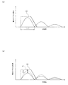
- an upper limit indicated by reference numeral 90 in FIG. 4A is imposed on the power spectrum density (dBm / MHz) as a UWB radio wave standard. Yes. In order not to exceed such an upper limit, it is required to appropriately adjust the waveform and output intensity of the pulse signal.
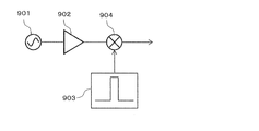
- a conventional pulse generator 900 includes a high-frequency oscillator 901 that transmits a high-frequency signal having a predetermined frequency, an amplifier 902 that amplifies the high-frequency signal output from the high-frequency oscillator 901, and a base that outputs a baseband pulse signal having a predetermined pulse width.
- a band pulse generation unit 903 and a mixer 904 that inputs and mixes the high-frequency signal amplified by the amplifier 902 and the pulse signal output from the baseband pulse generation unit 903 are provided.
- the mixer 904 up-converts the pulse signal input from the baseband pulse generator 903 with the high-frequency signal input from the amplifier 902, and outputs this as a high-frequency pulse signal.
- a high-frequency pulse signal By forming the pulse signal output from the baseband pulse generator 903 into a rectangular shape, an ultra-wideband pulse signal is output from the mixer 904.
- the high-frequency oscillator 901, the amplifier 902, and the mixer 904 are always in operation, and output an ultra-wideband high-frequency pulse signal only when a pulse signal is input from the baseband pulse generator 903.
- the mixer has at most about 20 dB as an isolation performance with respect to the leakage signal. Therefore, in the radar using this pulse generation device, as illustrated in FIG. 4B, a leakage signal of a relatively high level (indicated by reference numeral 91 in FIG. 4B) is superimposed on the received signal. . In order to keep the restriction on the power spectral density (dBm / MHz), it is necessary to reduce the power of the transmission signal as shown in FIG. As a result, there is a problem that the detectable distance is shortened.
- the present invention has been made in view of the above problems, and an object of the present invention is to provide a pulse generation device that generates a pulse signal having a suitable waveform and realizes high isolation when no pulse signal is output.
- a first aspect of the pulse generator of the present invention is a pulse generator for amplifying a high-frequency signal output from a high-frequency oscillator by an amplifier and outputting a high-frequency pulse signal, one end of which is a voltage
- a resistor connected to the power supply; a capacitor having one end connected to the input end and the other end connected to the other end of the resistor; a NOT logic type transistor having one end connected to the other end of the resistor;
- a current amplifier connected to the transistor and having the other end connected to the output end, a drive circuit for supplying driving power to the amplifier connected to the output end, and the drive power being shaped into a predetermined waveform
- a waveform control unit that outputs a control signal to the input terminal so as to be output from the drive circuit, and the transistor inputs the control signal through the capacitor, Les turns on the current amplifier when less than the predetermined threshold value, characterized in that at other times are controlled to be turned off.
- the threshold value is between a voltage bias set via the resistor from the voltage power supply and a minimum value of the control signal input from the capacitor. And it is set lower than the minimum value of the unnecessary voltage oscillation accompanying the said control signal, It is characterized by the above-mentioned.
- the waveform control unit includes timing control means for controlling the rising / falling timing of the driving power with high accuracy, and the rising speed / falling speed of the driving power. And a waveform shaping means for shaping the waveform into pulses, an amplitude control means for controlling the height of the driving power, and an intensity control means for controlling the strength of the driving power by a current. To do.
- the waveform control unit is configured using a SerDes (Serializer / Deserializer) of a PLD (Programmable Logic Device).
- the waveform control unit is configured using SerDes of FPGA (Field Programmable Gate Gate Array).
- Another aspect of the pulse generation device of the present invention is characterized in that the waveform control unit uses multi-stage pre-emphasis which the emphasis function of the FPGA has as the waveform shaping means.
- the waveform control unit selects the maximum value of the multi-stage pre-emphasis as the waveform shaping means, and the maximum value of the multi-stage current intensity as the intensity control means. It is characterized by selecting.
- the present invention it is possible to provide a pulse generation device that generates a pulse signal having a suitable waveform and realizes high isolation when no pulse signal is output.
- FIG. 1 is a block diagram illustrating a configuration of a pulse generation device according to a first embodiment of the present invention. It is a time waveform figure which shows an example of the ultra-wideband high frequency pulse signal produced
- FIG. 1 is a block diagram illustrating a configuration of a pulse generation device 100 according to the present embodiment.
- a pulse generation device 100 amplifies a high frequency signal output from a high frequency oscillator 101 by an amplifier 102 and outputs the amplified signal.
- the amplifier 102 amplifies and outputs the high frequency signal from the high frequency oscillator 101 only while the drive power is supplied from the drive circuit 110.
- the waveform control unit 120 is used to convert the waveform of the drive power supplied from the drive circuit 110 to the amplifier 102 so that the high-frequency signal amplified by the amplifier 102 becomes an ultra-wideband pulse signal. Control.
- the amplifier 102 is not limited to one stage, and may be configured to be connected in series with two or more stages.
- the drive circuit 110 includes a resistor (pull-up resistor) 111 having one end connected to the power supply of the voltage VDD, a capacitor 112 having one end connected to the input end 114 and the other end connected to the other end of the resistor 111, and a capacitor 112
- a NOT logic type transistor 113 having one end connected to the other end of the resistor 111 and a current amplifier 115 having one end connected to the transistor 113 and the other end connected to the output end 116 are provided.
- the input end 114 is connected to the waveform control unit 120 to input a predetermined control signal, and the output end 116 is connected to the amplifier 102 to supply the driving power.
- the current amplifier 115 amplifies the current output from the transistor 113 and supplies power necessary for driving the amplifier 102.
- the waveform control unit 120 is a means for shaping the waveform of the drive power output from the drive circuit 110, a timing control means 121 for controlling the rising / falling timing of the drive power with high accuracy, and a rising speed / A waveform shaping means 122 for shaping the waveform into pulses by controlling the falling speed, an amplitude control means 123 for controlling the height of the drive voltage, and an intensity control means 124 for controlling the intensity of the drive power by the current.
- a timing control means 121 for controlling the rising / falling timing of the drive power with high accuracy
- a rising speed / A waveform shaping means 122 for shaping the waveform into pulses by controlling the falling speed
- an amplitude control means 123 for controlling the height of the drive voltage
- an intensity control means 124 for controlling the intensity of the drive power by the current.
- a driving voltage of about 2 to 3 V and a driving current of about 60 mA are required.
- the drive voltage required for driving the amplifier 102 is raised or lowered at a predetermined timing at a high speed. It is necessary to control the waveform in a high frequency band.
- SerDes Serializer / Deserializer
- FPGA Field Programmable Gate Array
- the signal output from the SerDes of the FPGA has an amplitude of about 350 mV and is lower than the voltage required to drive the amplifier 102.
- the SerDes output signal also has problems such as overshoot and undershoot and ringing after signal output. Therefore, it is difficult to directly turn on / off the amplifier 102 using the FPGA. Therefore, in the pulse generation device 100 of the present embodiment, a drive circuit 110 is provided in order to supply drive power (drive voltage and drive current) having a suitable waveform to the amplifier 102.
- the drive power output from the drive circuit 110 is controlled using the waveform control unit 120.
- the SerDes of the FPGA described above can be used.
- the pulse generation device 100 of this embodiment is configured to generate and output an ultra-wideband high-frequency pulse signal as shown in FIG. 2, for example.
- the pulse height of the pulse signal 10 is Vp
- the pulse width is Tw
- the rise time and fall time are Tu and Td, respectively.
- the pulse width Tw 1 ns ⁇ 150 ps
- the rise time Tu fall time Td ⁇ 200 ps.
- the pulse width Tw is a time width at 1 ⁇ 2 of the pulse height Vp.
- the waveform controller 120 controls the drive power output from the drive circuit 110 so that the pulse signal 10 is output from the amplifier 102.
- the waveform control unit 120 can start / stop driving power output at a predetermined timing using the timing control means 121. Further, the rising speed / falling speed of the driving power can be controlled using the waveform shaping means 122, and the rising time Tu / falling time Td of the high-frequency pulse signal 10 can be set to 200 ps or less, for example.
- the pulse height Vp of the high frequency pulse signal 10 can be controlled using the amplitude control means 123.
- the intensity of the high-frequency pulse signal 10 can be controlled using the intensity control means 124.
- the intensity control unit 124 can control the intensity of the driving power output from the drive circuit 110 by controlling the current to the drive circuit 110.
- FIG. 3 shows an example of a control signal output from the waveform control unit 120 to the drive circuit 110 and a drive voltage output from the drive circuit 110 to the amplifier 102 in accordance with the control signal.
- reference numeral 21 denotes a drive voltage output to the amplifier 102
- reference numeral 22 denotes a control signal voltage output to the drive circuit 110.
- a control signal having a voltage of 120 to 300 mV and a current of about 24 mA is output from the waveform control unit 120 to the drive circuit 110.
- the current can be set to 24 mA by using the maximum setting value in the intensity control means 124.
- ringing can be reduced by using the transistor 113.
- drive power with a voltage of 2 to 3 V and a current of about 60 mA is output from the drive circuit 110 to the amplifier 102.
- the drive circuit 110 is configured to supply the drive voltage 21 as shown in FIG. 3 to the amplifier 102 in accordance with the control signal 22 output from the waveform control unit 120.
- the drive circuit 110 is configured to turn on / off the drive power of the current amplifier 115 that supplies the drive voltage 21 to the amplifier 102 by using a NOT logic type transistor 113.
- the transistor 113 operates as a comparator that compares the input signal with a predetermined threshold (Vt) and outputs a signal of “H” (High) or “L” (Low). When the output signal of the transistor 113 is “H”, driving power is supplied to the current amplifier 115.
- the transistor 113 is connected to a resistor 111 having one end connected to a power supply having a voltage VDD, and a predetermined voltage bias (DC bias VDC) is applied thereto.
- the DC bias VDC is set to about 600 mV necessary for driving the transistor 113.
- the transistor 113 In order to use the transistor 113 as the NOT logic type, an input signal is input to the inverting input side, and a signal of “H” is output from the transistor 113 when the voltage of the input signal is lower than the threshold value Vt. Therefore, the threshold value Vt is normally set lower than the DC bias VDC so that an “L” signal is output from the transistor 113.
- the control signal 22 as shown in FIG. 3 is input from the waveform control unit 120 to the drive circuit 110, the AC component of the control signal 22 is input through the capacitor 112 and added to the DC bias VDC.
- This added signal (VBE) is schematically shown in FIG.
- the signal shown in FIG. 7A is obtained by shaping the signal having a constant pulse length (duty ratio is 1: 1) as shown in FIG.
- the waveform control unit 120 the amplitude of the pulse exceeding the DC bias VDC is made as small as possible, and the waveform is shaped so that the areas of the signals oscillating up and down with respect to the DC bias VDC are equal. As a result, as illustrated in FIG.
- the waveform controller 120 outputs a signal whose voltage exceeding the DC bias VDC is significantly reduced and whose period is long and the duty ratio is significantly high.
- the duty ratio is preferably 1: 100 or more.
- a duty ratio of 1 corresponds to a downwardly convex pulse signal.
- the transistor 113 When a signal having a significantly high duty ratio as illustrated in FIG. 7A is input to the transistor 113, the amplitude of the pulse signal that protrudes below the DC bias VDC is large, and thus the threshold Vt of the transistor 113 Is easily set between the DC bias VDC and the voltage of the pulse signal projecting downward. Thus, when the pulse signal projecting downward is lower than the threshold value Vt, the transistor 113 outputs an “H” signal. When the pulse signal is again higher than the threshold value Vt, the transistor 113 outputs an “L” signal. Is output.
- the threshold value Vt of the transistor 113 can be easily set between the two.
- the drive voltage 21 supplied to the amplifier 102 is formed in a pulse shape between times T1 and T2, and the influence of ringing or the like can be sufficiently reduced. .
- the control signal 22 that rises at high speed can be output to the drive circuit 110 using the emphasis function of the FPGA.
- 16 steps of pre-emphasis can be set as the waveform shaping unit 122, and 8 steps of current intensity can be set as the strength control unit 124.
- the drive circuit 110 can output a control signal 22 as shown in FIG. 3 by setting the maximum values of the waveform shaping means 122 and the intensity control means 124.
- the waveform control unit 120 may be configured using SerDes of PLD (Programmable Logic) Device instead of the FPGA.
- the current amplifier 115 the current of the signal “H” output from the transistor 113 is amplified to about 60 mA, and the voltage is also amplified to 2 to 3V. Alternatively, the voltage may be amplified by the transistor 113.
- the waveform control unit 120 significantly increases the duty ratio of the control signal, and by inputting this to the transistor 113, the drive power supplied to the amplifier 102 is reliably input / output. It can be turned off. As a result, the isolation of the amplifier 102 when no high-frequency pulse signal is output can be greatly increased.
- the waveform control unit 120 controls the drive circuit 110, so that the amplifier 102 can output a suitable broadband high-frequency pulse signal 10. . That is, as the drive power supplied to the amplifier 102, the required pulse height and intensity can be realized by the drive circuit 110 by the control from the waveform control unit 120. According to the pulse generation device 100 of the present embodiment, it is possible to generate a high-frequency pulse signal having a suitable waveform and to achieve high isolation when no pulse signal is output.
- the description in the present embodiment shows an example of the pulse generation device according to the present invention, and the present invention is not limited to this.
- the detailed configuration and detailed operation of the pulse generation device according to the present embodiment can be changed as appropriate without departing from the spirit of the present invention.
Landscapes
- Engineering & Computer Science (AREA)
- Computer Networks & Wireless Communication (AREA)
- Physics & Mathematics (AREA)
- Power Engineering (AREA)
- Signal Processing (AREA)
- Nonlinear Science (AREA)
- General Physics & Mathematics (AREA)
- Radar, Positioning & Navigation (AREA)
- Remote Sensing (AREA)
- Amplifiers (AREA)
- Manipulation Of Pulses (AREA)
- Radar Systems Or Details Thereof (AREA)
Abstract
La présente invention concerne un dispositif de génération d'impulsions qui génère un signal d'impulsion ayant une forme d'onde appropriée et permet une forte isolation lorsqu'aucun signal d'impulsion ne sort. Au moyen d'un amplificateur (102), le dispositif de génération d'impulsions (100) amplifie un signal à haute fréquence provenant d'un oscillateur à hautes fréquences (101) et sort le résultat. L'amplificateur (102) n'amplifie et sort le signal à haute fréquence provenant de l'oscillateur à hautes fréquences (101) que lorsqu'un circuit de commande (110) délivre une puissance de commande. Une unité de commande de forme d'onde (120) sert à commander la forme d'onde de la puissance de commande délivrée par le circuit de commande (110) à l'amplificateur (102) d'une manière telle que le signal à haute fréquence amplifié par l'amplificateur (102) devient un signal d'impulsion à bande ultra-large.
Priority Applications (4)
| Application Number | Priority Date | Filing Date | Title |
|---|---|---|---|
| EP12763772.6A EP2693638A4 (fr) | 2011-03-28 | 2012-03-28 | Dispositif de génération d'impulsions |
| CN2012800133479A CN103430451A (zh) | 2011-03-28 | 2012-03-28 | 脉冲生成装置 |
| JP2013507701A JPWO2012133593A1 (ja) | 2011-03-28 | 2012-03-28 | パルス生成装置 |
| US14/039,610 US20140043083A1 (en) | 2011-03-28 | 2013-09-27 | Pulse generator |
Applications Claiming Priority (2)
| Application Number | Priority Date | Filing Date | Title |
|---|---|---|---|
| JP2011-070480 | 2011-03-28 | ||
| JP2011070480 | 2011-03-28 |
Related Child Applications (1)
| Application Number | Title | Priority Date | Filing Date |
|---|---|---|---|
| US14/039,610 Continuation US20140043083A1 (en) | 2011-03-28 | 2013-09-27 | Pulse generator |
Publications (1)
| Publication Number | Publication Date |
|---|---|
| WO2012133593A1 true WO2012133593A1 (fr) | 2012-10-04 |
Family
ID=46931300
Family Applications (1)
| Application Number | Title | Priority Date | Filing Date |
|---|---|---|---|
| PCT/JP2012/058262 Ceased WO2012133593A1 (fr) | 2011-03-28 | 2012-03-28 | Dispositif de génération d'impulsions |
Country Status (5)
| Country | Link |
|---|---|
| US (1) | US20140043083A1 (fr) |
| EP (1) | EP2693638A4 (fr) |
| JP (1) | JPWO2012133593A1 (fr) |
| CN (1) | CN103430451A (fr) |
| WO (1) | WO2012133593A1 (fr) |
Families Citing this family (5)
| Publication number | Priority date | Publication date | Assignee | Title |
|---|---|---|---|---|
| WO2014157496A1 (fr) * | 2013-03-29 | 2014-10-02 | 古河電気工業株式会社 | Dispositif de génération d'impulsion |
| JP6352963B2 (ja) * | 2016-03-09 | 2018-07-04 | 株式会社東芝 | アンテナ装置及びアレイアンテナ装置 |
| CN107329134B (zh) * | 2017-06-29 | 2021-03-30 | 电子科技大学 | 一种基于阵元馈电波形控制的波控阵超宽带雷达天线阵列 |
| CN110045372B (zh) * | 2019-03-11 | 2021-03-23 | 西安电子科技大学 | 超宽带脉冲信号发射装置及超宽带脉冲雷达系统 |
| DE202021105937U1 (de) | 2021-10-29 | 2022-02-04 | TRUMPF Hüttinger GmbH + Co. KG | Steuerschaltung für Treiber |
Citations (3)
| Publication number | Priority date | Publication date | Assignee | Title |
|---|---|---|---|---|
| JP2007174087A (ja) * | 2005-12-20 | 2007-07-05 | Matsushita Electric Ind Co Ltd | パルス発生回路 |
| JP2007174028A (ja) * | 2005-12-20 | 2007-07-05 | Samsung Electronics Co Ltd | パルスジェネレータおよびそのパルスジェネレータを用いたインパルス無線送信機 |
| JP2009222457A (ja) | 2008-03-14 | 2009-10-01 | Furukawa Electric Co Ltd:The | パルス発生方法、パルス発生装置およびレーダ装置 |
Family Cites Families (8)
| Publication number | Priority date | Publication date | Assignee | Title |
|---|---|---|---|---|
| FR2625327B1 (fr) * | 1987-12-23 | 1992-04-30 | Omera Segid Optique Meca Elect | Radar a compression d'impulsions et application a la cartographie ou a la meteorologie |
| US7209523B1 (en) * | 1997-05-16 | 2007-04-24 | Multispectral Solutions, Inc. | Ultra-wideband receiver and transmitter |
| US5990751A (en) * | 1997-10-16 | 1999-11-23 | Nikon Corporation | Method and apparatus for improving power transfer efficiency of an amplifier system |
| US7522004B2 (en) * | 2004-11-15 | 2009-04-21 | Anritsu Corporation | High-frequency electronic switch, and burst wave generating device using the same and short range radar using the same |
| US7949316B2 (en) * | 2008-01-29 | 2011-05-24 | Panasonic Corporation | High-efficiency envelope tracking systems and methods for radio frequency power amplifiers |
| CN101262239B (zh) * | 2008-03-21 | 2012-01-18 | 南京誉葆科技有限公司 | 毫米波射频收发装置 |
| JP5472119B2 (ja) * | 2008-12-25 | 2014-04-16 | 日本電気株式会社 | 電力増幅装置 |
| US7782141B2 (en) * | 2008-12-29 | 2010-08-24 | Texas Instruments Incorporated | Adaptive signal-feed-forward circuit and method for reducing amplifier power without signal distortion |
-
2012
- 2012-03-28 WO PCT/JP2012/058262 patent/WO2012133593A1/fr not_active Ceased
- 2012-03-28 JP JP2013507701A patent/JPWO2012133593A1/ja active Pending
- 2012-03-28 CN CN2012800133479A patent/CN103430451A/zh active Pending
- 2012-03-28 EP EP12763772.6A patent/EP2693638A4/fr not_active Withdrawn
-
2013
- 2013-09-27 US US14/039,610 patent/US20140043083A1/en not_active Abandoned
Patent Citations (3)
| Publication number | Priority date | Publication date | Assignee | Title |
|---|---|---|---|---|
| JP2007174087A (ja) * | 2005-12-20 | 2007-07-05 | Matsushita Electric Ind Co Ltd | パルス発生回路 |
| JP2007174028A (ja) * | 2005-12-20 | 2007-07-05 | Samsung Electronics Co Ltd | パルスジェネレータおよびそのパルスジェネレータを用いたインパルス無線送信機 |
| JP2009222457A (ja) | 2008-03-14 | 2009-10-01 | Furukawa Electric Co Ltd:The | パルス発生方法、パルス発生装置およびレーダ装置 |
Also Published As
| Publication number | Publication date |
|---|---|
| US20140043083A1 (en) | 2014-02-13 |
| EP2693638A4 (fr) | 2014-10-01 |
| JPWO2012133593A1 (ja) | 2014-07-28 |
| CN103430451A (zh) | 2013-12-04 |
| EP2693638A1 (fr) | 2014-02-05 |
Similar Documents
| Publication | Publication Date | Title |
|---|---|---|
| WO2012133593A1 (fr) | Dispositif de génération d'impulsions | |
| Xu et al. | Power-efficient switching-based CMOS UWB transmitters for UWB communications and radar systems | |
| JP6163308B2 (ja) | 短光パルス発生装置 | |
| JP2013083541A (ja) | Rfパルス信号生成用スイッチング回路、rfパルス信号生成回路、および物標探知装置 | |
| JP4685060B2 (ja) | 差動発振装置 | |
| KR20190025653A (ko) | 고주파 전원 장치 | |
| JP5356133B2 (ja) | Pwmパルス生成装置 | |
| US20130285728A1 (en) | Pulse generator | |
| JP2009531930A (ja) | 自己較正ミキサ | |
| WO2007023866A1 (fr) | Circuit à fonctionnement intermittent et dispositif de modulation | |
| US7554414B2 (en) | Fast starting circuit for crystal oscillators | |
| CN104765027A (zh) | 高频超声编码激励发射系统及脉冲产生方法 | |
| KR101646226B1 (ko) | 초광대역 임펄스 발생기 | |
| JP5027177B2 (ja) | インパルス生成装置 | |
| JP4648861B2 (ja) | パルスレーダ送信機 | |
| US7808224B2 (en) | High-frequency power supply circuit | |
| JP5140611B2 (ja) | 電力増幅器の調整方法 | |
| JP4517884B2 (ja) | 無線送信回路及び無線送信装置 | |
| KR20100111343A (ko) | 반도체 파형 발생기 | |
| KR101504987B1 (ko) | 삼각파를 이용한 저전력 발진기 | |
| JP3979345B2 (ja) | 無線送信回路 | |
| JP2008252214A (ja) | デューティ比制御高周波生成回路 | |
| JP4630794B2 (ja) | 無線送信回路 | |
| KR101502770B1 (ko) | 펄스레이저 구동제어 회로 | |
| JP2009250644A (ja) | ジッタ検出回路 |
Legal Events
| Date | Code | Title | Description |
|---|---|---|---|
| 121 | Ep: the epo has been informed by wipo that ep was designated in this application |
Ref document number: 12763772 Country of ref document: EP Kind code of ref document: A1 |
|
| ENP | Entry into the national phase |
Ref document number: 2013507701 Country of ref document: JP Kind code of ref document: A |
|
| NENP | Non-entry into the national phase |
Ref country code: DE |
|
| WWE | Wipo information: entry into national phase |
Ref document number: 2012763772 Country of ref document: EP |