WO2012133702A1 - Dispositif de station de base et procédé de fixation d'un capot - Google Patents
Dispositif de station de base et procédé de fixation d'un capot Download PDFInfo
- Publication number
- WO2012133702A1 WO2012133702A1 PCT/JP2012/058475 JP2012058475W WO2012133702A1 WO 2012133702 A1 WO2012133702 A1 WO 2012133702A1 JP 2012058475 W JP2012058475 W JP 2012058475W WO 2012133702 A1 WO2012133702 A1 WO 2012133702A1
- Authority
- WO
- WIPO (PCT)
- Prior art keywords
- lid
- state
- opening
- base station
- station apparatus
- Prior art date
- Legal status (The legal status is an assumption and is not a legal conclusion. Google has not performed a legal analysis and makes no representation as to the accuracy of the status listed.)
- Ceased
Links
Images



Classifications
-
- H—ELECTRICITY
- H04—ELECTRIC COMMUNICATION TECHNIQUE
- H04B—TRANSMISSION
- H04B1/00—Details of transmission systems, not covered by a single one of groups H04B3/00 - H04B13/00; Details of transmission systems not characterised by the medium used for transmission
- H04B1/38—Transceivers, i.e. devices in which transmitter and receiver form a structural unit and in which at least one part is used for functions of transmitting and receiving
-
- H—ELECTRICITY
- H05—ELECTRIC TECHNIQUES NOT OTHERWISE PROVIDED FOR
- H05K—PRINTED CIRCUITS; CASINGS OR CONSTRUCTIONAL DETAILS OF ELECTRIC APPARATUS; MANUFACTURE OF ASSEMBLAGES OF ELECTRICAL COMPONENTS
- H05K5/00—Casings, cabinets or drawers for electric apparatus
- H05K5/02—Details
- H05K5/03—Covers
-
- H—ELECTRICITY
- H05—ELECTRIC TECHNIQUES NOT OTHERWISE PROVIDED FOR
- H05K—PRINTED CIRCUITS; CASINGS OR CONSTRUCTIONAL DETAILS OF ELECTRIC APPARATUS; MANUFACTURE OF ASSEMBLAGES OF ELECTRICAL COMPONENTS
- H05K5/00—Casings, cabinets or drawers for electric apparatus
- H05K5/06—Hermetically-sealed casings
- H05K5/061—Hermetically-sealed casings sealed by a gasket held between a removable cover and a body, e.g. O-ring, packing
Definitions
- the present invention relates to a base station apparatus having a waterproof structure with high hermeticity and a method for attaching a lid.
- the base station equipment collects the connector terminals and power terminals required for maintenance / inspection work in one place and arranges the work area (or construction area) where these are arranged. Provided. Further, a lid is attached to the work area, and the work space can be exposed / sealed by opening and closing the lid.
- the base station apparatus is an electronic device, a waterproof structure having high hermeticity is important.
- the high sealing performance of the opening is provided. You may need a waterproof structure.
- the terminal board on which the connector terminal, the power terminal, etc. are placed is covered with a resin or the like.
- a separate member was used.
- the terminal board used in the above-described conventional technology has a waterproof function and is also equipped with connector terminals used for apparatus maintenance. For this reason, the whole must have a waterproof structure, which is very expensive and occupies much of the mechanical material cost.
- the present invention has been made in view of the above-described conventional circumstances, and an object of the present invention is to provide a base station apparatus that realizes a waterproof structure with higher sealing performance at a lower cost and a method of attaching a lid. Yes.
- a base station apparatus includes an enclosure having an opening, a lid, and an opening / closing mechanism that moves the lid between a first state in which the opening is opened and a second state in which the opening is closed.
- the casing includes a gasket around the opening, the lid includes a contact portion that contacts the gasket, and the opening / closing mechanism includes the first state of the lid and the lid
- a first movable mechanism that reversibly moves between a second state and a third state that is a predetermined distance in a direction perpendicular to the opening surface of the opening; and the second state of the lid;
- a second movable mechanism that reversibly moves between the third states of the lid, and when the lid is in the second state, a force is applied to the lid in a direction perpendicular to the opening surface;
- a fixing member for fixing the lid.
- the housing has a first protrusion and a second protrusion extending around and parallel to the opening, and the gasket is interposed between the first protrusion and the second protrusion. May be installed.
- the contact portion is a protrusion provided on the lid, and may contact the gasket in the second state.
- the housing includes a vertical guide extending perpendicularly to the opening surface, and an oblique guide connected to the vertical guide and extending from the vertical guide at a predetermined angle, and the lid includes the vertical guide.
- You may have an engaging member which can move along the said diagonal guide.
- the oblique guide and the engaging member may constitute the first movable mechanism
- the vertical guide and the engaging member may constitute the second movable mechanism.
- the opening may be provided on a side surface of the housing.
- the housing may have a circuit board including a connector terminal, and the connector terminal may be exposed in the opening.
- a base station apparatus includes a housing having a work area on one surface, a lid, a first state in which the work area is opened, and a second state in which the work area is closed.
- a base station device comprising an opening / closing mechanism for moving the lid and a notification unit for reporting an alarm, wherein the housing is disposed so as to surround the work area, and the work area.
- a switch having a movable portion that transitions from the first switch state to the second switch state by being pushed down in a direction perpendicular to the work area installation surface, and the lid is attached to the gasket.
- the opening / closing mechanism includes a state between the first state of the lid and a third state where the lid is at a predetermined distance in a direction perpendicular to the work area installation surface from the second state.
- a first movable mechanism that reversibly moves, a second movable mechanism that reversibly moves the lid between the second state and the third state of the lid, and the lid A fixing member that fixes the lid by applying a force to the lid in a direction perpendicular to the work area installation surface in the second state, and the notification unit has the switch in the first switch state. An alarm is announced at the time of.
- a plurality of work areas are provided for a set of one lid and an opening / closing mechanism for the lid, and the notification unit is configured such that any one of the plurality of switches is the first switch. You may alert
- the casing has parallel first protrusions and second protrusions surrounding the work area, and the gasket is between the first protrusions and the second protrusions. May be installed.
- the first movable mechanism may include a slide mechanism that slides the lid in one direction.
- the first movable mechanism may include a rotation mechanism that rotates the lid in one direction.
- the first movable mechanism is configured by a guide portion provided in parallel to the work area installation surface and an engaging member provided on the lid, and the engaging member is provided in the guide portion.
- the lid may move between the first state and the third state by moving along.
- the second movable mechanism is configured by a guide portion provided perpendicular to the work area installation surface and an engaging member provided on the lid, and the engaging member is provided in the guide portion. By moving along, the lid may move between the second state and the third state.
- the first movable mechanism is configured by a guide opening provided adjacent to the work area and an engaging member provided on the lid, and the engaging member is rotated by the guide opening.
- the lid may move between the first state and the third state by being movably inserted and the engaging member rotating in the guide.
- the second movable mechanism is configured by a guide portion provided perpendicular to the work area installation surface and an engaging member provided on the lid, and the engaging member is provided in the guide portion. By moving along, the lid may move between the second state and the third state.
- the fixing member may be a screw.
- the surface on which the work area is installed may be a side surface of the housing.
- a lid mounting method includes an opening and a housing having a gasket around the opening, a lid, a first state in which the opening is opened, and a second state in which the opening is closed.
- the base station apparatus comprising an opening / closing mechanism for moving the lid between the lids, the lid is attached from the first state by the opening / closing mechanism, and the lid is removed from the second state.
- the lid is moved to a third state at a predetermined distance in a direction perpendicular to the opening surface of the opening, the lid is moved from the third state to the second state by the opening / closing mechanism, and the second of the lid is moved. In this state, a force is applied to the lid in a direction perpendicular to the opening surface to fix the lid.
- the base station apparatus and the lid attachment method since the lid moves from the third state to the second state where the lid is closed, the gasket is compressed. The variation in the amount can be suppressed, and as a result, a waterproof structure having higher sealing performance at a lower cost can be realized.
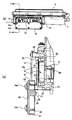
- FIG.1 (a) is a whole side view in the state which the cover opened
- FIG.1 (b) is a partial cross section figure.
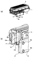
- Fig.2 (a) is a whole perspective view of the state which the cover opened
- FIG.2 (b) is a partial perspective view.
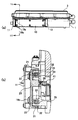
- Fig.3 (a) is a whole side view of the state which the cover closed
- FIG.3 (b) is a partial cross section figure.
- FIG.4 (a) is a whole perspective view of the state which the cover closed
- FIG.4 (b) is a partial perspective view.
- Fig.8 (a) is a whole perspective view in the state with the lid closed
- FIG.8 (b) is a partial perspective view.
- Fig.9 (a) is the whole perspective view of the state which the cover opened
- FIG.9 (b) is a partial perspective view.
- FIG. 1 (a) is an overall side view of the state in which the lid is open (first state)
- FIG. 1 (b) is a view taken along the plane IB-IB in FIG. 1 (a). It is sectional drawing to which the part was expanded.
- FIG. 2A is an overall perspective view with the lid open
- FIG. 2B is an enlarged perspective view of the front corner portion in FIG. 3 (a) is an overall side view of the state in which the lid is closed (second state)
- FIG. 1 (a) is an overall side view of the state in which the lid is closed (second state)
- FIG. 1 (a) is an overall side view of the state in which the lid is closed (second state)
- FIG. 3 (b) is a partial view taken along the line IIIB-IIIB in FIG. 3 (a).
- FIG. 4A is an overall perspective view in a state where the lid is closed
- FIG. 4B is an enlarged perspective view of the front corner portion in FIG. 4A.
- reference numeral 1 denotes a base station device casing
- 3 denotes fins installed on the upper surface of the base station device.
- the housing 1 has a work area (construction area) 8 that is installed on one side surface parallel to the longitudinal direction of the base station apparatus and on which a maintenance worker or a construction worker works.
- reference numeral 10 denotes a lid of the work area 8, and the opening / closing mechanism of the lid 10 is in a state where the work area 8 is opened (first state) and a state where the work area 8 is closed (second state). ) To move the lid 10.
- two work areas are provided for a set of one lid 10 and an opening / closing mechanism for the lid 10.
- one or three or more work areas may be provided for one lid 10 and a set of opening / closing mechanisms of the lid 10. Further, the surface on which the work area is installed may be provided on any surface of the housing 1 depending on the orientation when the base station device is attached outdoors.
- the housing 1 includes a first projection 32 and a second projection 33 on the housing side that run parallel to surround the work area 8, and a first projection 32 and a second projection. 33 has a gasket 35 installed in the groove 31 formed by 33.
- the housing 1 is mounted with various connector terminals, power supply terminals, and the like in the work area 8 (not identified in the figure).
- Various circuit boards are arranged on the inner side of the apparatus with respect to the bottom surface 9 of the work area 8 of the housing 1, and a microswitch 41 is installed on one of the boards 40.
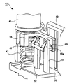
- FIG. 5 shows a perspective view of the micro switch 41 used in the present embodiment.
- the micro switch 41 serves as an open / close sensor for the lid 10 that detects whether or not the lid 10 is fixed to the housing 1 and is completely closed.
- An elastic force by the elastic member 47 is acting on the movable portion 45 at the upper part of the micro switch 41.
- the clip-shaped contact portions 48a and 48b are located between the first terminal 51 and the second terminal 52 as shown in FIG.
- the micro switch 41 is in the off state (first switch state) without conducting the.
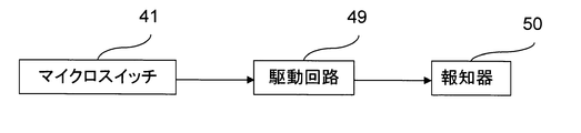
- the first terminal 51 and the second terminal 52 are connected to the drive circuit 49 of the alarm as shown in FIG.
- the drive circuit 49 drives the alarm 50 when the micro switch 41 is in the on state (second switch state), and drives the alarm 50 when the micro switch 41 is in the off state (first switch state).
- a warning sound is emitted from.
- the microswitch 41 is installed in each of the two work areas, and any one of the two microswitches 41 is in an off state (first state). An alarm is notified at the time of switch state.
- the movable portion 45 of the micro switch 41 is installed at a position exposed to the work area 8 through a hole opened in the bottom surface 9 of the work area 8 as shown in FIG. That is, the second protrusion 26 of the lid 10 contacts the upper surface of the movable portion 45 of the microswitch 41 through this hole, and pushes the movable portion 45 downward when the lid 10 is fixed to the housing 1. .
- the lid 10 is disposed so as to face the gasket 35, and faces the first projecting portion (contact portion) 22 that contacts the gasket 35 and the movable portion 45 of the microswitch 41 when the lid 10 is closed.
- the second protrusion 26 is in contact with the movable portion 45, the reinforcing portion 25 reinforces the strength of the second protrusion 26, and the outer peripheral portion 21.
- the outer peripheral portion 21 is not essential as a constituent requirement of the present embodiment, but deformation such as warpage of the lid 10 can be suppressed by adopting a structure including the outer peripheral portion 21.
- the double structure of the outer peripheral portion 21 and the first protruding portion 22 can further improve the sealing performance, and further functions as a guide for guiding the first protruding portion 22 to the groove portion 31 on the working area 8 side.
- the reinforcing portion 25 is appropriately provided when the second projecting portion 26 needs to be reinforced.
- the base station apparatus includes a first movable mechanism, a second movable mechanism, and a fixed member as an opening / closing mechanism for the lid 10.
- the first movable mechanism is embodied by the first guide member 11, the portion 13 a of the second guide member 13 arranged in parallel with the first guide member 11, and the engaging member 15 of the lid 10. Is done.
- the first movable mechanism is a state in which the lid 10 is opened by moving the engaging member 15 of the lid 10 in the vertical direction in FIG. 2B in the space formed by the first guide member 11 and the second guide member 13a.
- the third state that is a predetermined distance in the direction perpendicular to the installation surface of the work area 8 from the state in which the lid 10 is closed can be reversibly moved.
- the first guide member 11 is fixed to the housing 1 via an attachment member, and the predetermined distance in the third state is determined by the attachment height of the first guide member 11. It will be.
- the second movable mechanism is embodied by a portion 13 b of the second guide member 13 that is arranged perpendicular to the first guide member 11 and the engaging member 15 of the lid 10.
- the engagement member 15 of the lid 10 moves along the second guide member 13b in a space formed by the second guide member 13b and the portion of the housing 1, so that the lid 10 is closed.
- the lid 10 can be reversibly moved between the third state and the third state.
- the first guide member 11 and the second guide member portion 13a are arranged perpendicular to the second guide member 13 portion 13b, but the first guide member 11 and the second guide member portion 13a. Is not limited to being vertical as long as it is disposed obliquely with an angle with respect to the portion 13 b of the second guide member 13. It is designed appropriately depending on the direction in which the lid 10 opens.
- the fixing member includes mounting screws 19a, 19b... On the upper surface of the lid 10.
- the lid 10 can be fixed by applying a force to the lid 10 in a direction perpendicular to the installation surface of the work area 8 when the lid 10 is closed.
- the lid 10 may be temporarily fixed with a stopper or the like. By doing so, it is possible to prevent the lid 10 from being dropped or displaced.
- the lid 10 is fixed and completely closed (see FIGS. 3 and 3) from the state in which the lid 10 is opened (see FIGS. 1 and 2).
- the fixing member that fixes the lid 10 is not limited to the mounting screws 19a and 19b.
- the lid 10 may be fixed to the casing 1 by providing the casing 1 with an engaging portion that engages with the lid 10 in a state where the lid 10 is completely closed.
- the work area 8 is installed on one surface of the housing 1 of the base station apparatus, and the work area 8 is opened by the opening / closing mechanism of the lid 10.
- the base station apparatus moves the lid 10 between the closed state and the casing 1, and the housing 1 includes a gasket 35 installed so as to surround the work area 8, and the lid 10 faces the gasket 35.
- the lid 10 is in a closed state, the first projection 22 is in contact with the gasket 35. Further, as an opening / closing mechanism of the lid 10, the lid 10 is opened and the lid 10 is closed.
- a first movable mechanism for reversibly moving between a third state at a predetermined distance in a direction perpendicular to the area 8 installation surface, a state in which the lid 10 is closed, and a third state of the lid 10 A second movable mechanism that reversibly moves between the states of In a state where the lid is closed, by applying a force in a direction perpendicular to the working area 8 installation surface on the cover 10, a fixing member for fixing the lid 10 (the mounting screw 19a, 19b, ...) and, a configuration having a.
- the second movable mechanism moves from the third state of the lid 10 to the closed state of the lid 10 along the direction perpendicular to the installation surface of the work area 8, and is fixed by the fixing member.
- the gasket 35 is compressed by applying a vertical force to the gasket 35. For this reason, the variation in the compression amount of the gasket 35 can be suppressed, and as a result, a waterproof structure having higher sealing performance at a lower cost can be realized.
- the chassis 1 is installed at a predetermined position in the work area 8, and is turned off when the movable portion 45 is pushed down in a direction perpendicular to the work area 8 installation surface (first switch state).
- the microswitch 41 is switched from ON to the second switch state (the second switch state), and the lid 10 is disposed to face the movable portion 45 of the microswitch 41.
- the lid 10 contacts the movable portion 45.
- Two protrusions 26 are provided.
- the opening / closing judgment of the lid 10 by the micro switch 41 will be considered.
- the mounting screw 19 is turned with a specified torque, and the gasket 35 is compressed on the first protrusion 22 by applying a force in a direction perpendicular to the work area 8 installation surface.
- the micro switch 41 transitions from the off state to the on state. Therefore, in the process of fastening the mounting screw 19, the micro switch 41 to be used is the same as the micro switch 41 to be used in a state in which the first protrusion 22 compresses the gasket 35 to ensure the sealing property. It is necessary to transition from the off state to the on state.
- the variation in the ON state is smaller than that of other switches, but has a tolerance that cannot be ignored.
- the tolerance of other members since the tolerance of other members, the tolerance of the members themselves, and assembly errors are added to this, the position where the microswitch 41 is turned on greatly fluctuates.
- the gasket 35 itself also varies in compression amount due to tolerances of other members, tolerances of the members themselves, assembly errors, and the like.
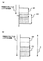
- the compression amount R of the gasket 35 in consideration of the variation P of the position where the microswitch 41 is turned on and the variation Q of the gasket 35. If the above-mentioned points are not taken into account, for example, as shown in FIG. 7A, when the position where a certain microswitch 41 is turned on is the S point, it is influenced by the variation in the compression amount of the gasket 35. In some cases, the movable portion 45 cannot be pushed down to the point S. In this case, even if the lid 10 is closed and has a sealing property, the microswitch 41 does not transition from the off state to the on state, and the microswitch 41 does not correctly determine whether the lid 10 is opened or closed.
- the compression amount in the gasket 35 to be used is determined from the variation P in the position where the microswitch 41 is turned on and the variation amount Q in the compression amount in the gasket 35.
- P is a value calculated from a stacking tolerance calculated by averaging each tolerance generated by a tolerance of other members, a tolerance of the member itself, an assembly error, and the like, and a variation based on processing accuracy.
- Q is a value calculated from a stacking tolerance calculated by averaging each tolerance generated by a tolerance of another member, a tolerance of the member itself, an assembly error, and the like, and a variation based on processing accuracy.
- the minimum value of the maximum width that the movable part 45 can push down in the direction perpendicular to the installation surface of the work area 8 is set to be equal to or greater than the width Z of the compression amount of the gasket 35 described above.
- the movable part 45 is installed in the work area 8.
- the lid 10 can be opened and closed more accurately in this way, if the maintenance worker forgets to close the lid 10 or forgets to fasten the mounting screws 19a, 19b. Even if it gradually loosens, an alarm can be issued when the designed waterproof line is exceeded.
- the lid 10 is moved along the guide by the first movable mechanism and the second movable mechanism, so that it is not possible for the operator to close the lid 10 by force during the operation of closing the lid 10. As a result, breakage of the lid 10 can be prevented.
- the first movable mechanism and the second movable mechanism are provided on both sides of the lid 10, but by changing the hinge cross-sectional shape of both the lid 10, the work area 8 is installed from a fixed position. It is possible to make the structure closed in a direction perpendicular to the surface.
- FIG.8 and FIG.9 is a block diagram of the base station apparatus which concerns on 2nd Embodiment of this invention.
- FIG. 8A is an overall perspective view in a state where the lid is opened (first state)
- FIG. 8B is an enlarged perspective view of the upper left corner portion in FIG. 8A
- FIG. 9A is an overall perspective view in a state where the lid is closed (second state)
- FIG. 9B is an enlarged perspective view of the upper left corner portion in FIG. 9A.
- reference numeral 101 denotes a base station apparatus casing.
- work areas where maintenance workers or construction workers work are installed on the upper and lower surfaces parallel to the longitudinal direction of the base station apparatus.
- reference numerals 102 and 103 each denote a lid structure.
- the lid structure 103 the working area is opened (first state) and the working area is closed (first state) by the opening / closing mechanism of the lid 110 ( Second state).
- Second state the opening / closing mechanism of the lid 110
- This embodiment is different from the first embodiment in that the first movable mechanism of the lid opening / closing mechanism is the slide method in the first embodiment, whereas the rotation method is used in the present embodiment. is there.
- the other lid opening / closing mechanism is the same as that of the first embodiment, and the structure of the back side of the lid and the structure of the work area are the same as those of the first embodiment except for the shape.
- the first movable mechanism of the present embodiment includes a first guide member 112 (112a and 112b), a second guide member 113 (113a, 113b and 113c), and an engaging member 115 of the lid 110.
- the engaging member 115 of the lid 110 is moved in the space (guide opening) formed by the first guide member 112 and the second guide member 113, and the lid 110 is rotated about the short side direction of the housing 101 as an axis.
- the lid 10 can be moved to the opened state, the third state, and the closed state with a simple structure.
- the lid 110 moves from the third state to the closed state along the direction perpendicular to the work area installation surface. For this reason, variation in the compression amount of the gasket can be suppressed, and as a result, a waterproof structure having higher sealing performance at a lower cost can be realized. In addition, since the variation in the compression amount of the gasket is suppressed, the opening / closing judgment of the lid 110 by the microswitch can be performed more accurately.
- the lid 10 is provided for the work area 8 of the base station apparatus.
- the base station apparatus has an opening, and a waterproof structure in which the opening is sealed with the lid. You may need it.
- the waterproof structure of the above embodiment can be applied not only to the work area 8 but also to the opening of such a base station apparatus.
- the lid 110 is rotated about the short side direction of the housing 101 by the first movable mechanism, but may be configured to rotate about the long side direction of the housing 101. .
- the present invention is suitably used for a base station apparatus that requires a waterproof structure.
Landscapes
- Engineering & Computer Science (AREA)
- Microelectronics & Electronic Packaging (AREA)
- Computer Networks & Wireless Communication (AREA)
- Signal Processing (AREA)
- Casings For Electric Apparatus (AREA)
Abstract
L'invention concerne un dispositif de station de base comprenant une armoire (1) présentant une ouverture, un capot (10) et un mécanisme d'ouverture/fermeture destiné à faire passer ledit capot entre un premier état dans lequel ladite ouverture est ouverte et un deuxième état dans lequel ladite ouverture est fermée, ladite armoire présentant un joint d'étanchéité sur le pourtour de ladite ouverture, ledit capot présentant une partie de contact établissant un contact avec ledit joint d'étanchéité et ledit mécanisme d'ouverture/fermeture comportant un premier mécanisme mobile (11, 13a, 15) destiné à déplacer de manière réversible le capot entre ledit premier état du capot et un troisième état du capot dans lequel le capot se trouve à une distance donnée dudit deuxième état du capot, dans une direction orthogonale à la surface d'ouverture de ladite ouverture, un deuxième mécanisme mobile (13b, 15) destiné à déplacer de manière réversible le capot entre le deuxième état et le troisième état du capot, et un organe de fixation (19a, 19b) destiné à appliquer une force au capot dans une direction orthogonale à la surface d'ouverture correspondant audit deuxième état du capot, pour ainsi fixer le capot.
Priority Applications (1)
| Application Number | Priority Date | Filing Date | Title |
|---|---|---|---|
| JP2013507749A JP5640144B2 (ja) | 2011-03-29 | 2012-03-29 | 基地局装置および蓋の取り付け方法 |
Applications Claiming Priority (2)
| Application Number | Priority Date | Filing Date | Title |
|---|---|---|---|
| JP2011071469 | 2011-03-29 | ||
| JP2011-071469 | 2011-03-29 |
Publications (1)
| Publication Number | Publication Date |
|---|---|
| WO2012133702A1 true WO2012133702A1 (fr) | 2012-10-04 |
Family
ID=46931404
Family Applications (1)
| Application Number | Title | Priority Date | Filing Date |
|---|---|---|---|
| PCT/JP2012/058475 Ceased WO2012133702A1 (fr) | 2011-03-29 | 2012-03-29 | Dispositif de station de base et procédé de fixation d'un capot |
Country Status (2)
| Country | Link |
|---|---|
| JP (1) | JP5640144B2 (fr) |
| WO (1) | WO2012133702A1 (fr) |
Cited By (3)
| Publication number | Priority date | Publication date | Assignee | Title |
|---|---|---|---|---|
| CN106686930A (zh) * | 2015-11-06 | 2017-05-17 | 青岛海尔滚筒洗衣机有限公司 | 一种防水pcb板盒及具有该板盒的洗衣机 |
| CN113347839A (zh) * | 2021-06-19 | 2021-09-03 | 九江职业技术学院 | 一种抗干扰电子通信装置 |
| JP2025501162A (ja) * | 2022-05-27 | 2025-01-17 | 楽天シンフォニー株式会社 | 通信デバイスのための自己冷却シャーシ |
Citations (8)
| Publication number | Priority date | Publication date | Assignee | Title |
|---|---|---|---|---|
| JPS4940501Y1 (fr) * | 1968-11-21 | 1974-11-07 | ||
| JPH01133789U (fr) * | 1988-03-03 | 1989-09-12 | ||
| JPH114084A (ja) * | 1997-06-12 | 1999-01-06 | Hitachi Ltd | 電子機器用筐体 |
| JP2000049518A (ja) * | 1998-07-30 | 2000-02-18 | Kajima Corp | 電波反射性壁面へのphs基地局アンテナ設置方法及び装置 |
| JP2000049680A (ja) * | 1998-07-30 | 2000-02-18 | Sanyo Electric Co Ltd | 携帯電話システムの基地局ユニット |
| JP2004311660A (ja) * | 2003-04-04 | 2004-11-04 | Hitachi Kokusai Electric Inc | 電子機器の筐体構造 |
| JP2006313853A (ja) * | 2005-05-09 | 2006-11-16 | Fuji Photo Film Co Ltd | 防水構造 |
| JP2010124072A (ja) * | 2008-11-17 | 2010-06-03 | Nec Corp | 筐体の防水機構、筐体組立方法および携帯端末装置 |
-
2012
- 2012-03-29 JP JP2013507749A patent/JP5640144B2/ja not_active Expired - Fee Related
- 2012-03-29 WO PCT/JP2012/058475 patent/WO2012133702A1/fr not_active Ceased
Patent Citations (8)
| Publication number | Priority date | Publication date | Assignee | Title |
|---|---|---|---|---|
| JPS4940501Y1 (fr) * | 1968-11-21 | 1974-11-07 | ||
| JPH01133789U (fr) * | 1988-03-03 | 1989-09-12 | ||
| JPH114084A (ja) * | 1997-06-12 | 1999-01-06 | Hitachi Ltd | 電子機器用筐体 |
| JP2000049518A (ja) * | 1998-07-30 | 2000-02-18 | Kajima Corp | 電波反射性壁面へのphs基地局アンテナ設置方法及び装置 |
| JP2000049680A (ja) * | 1998-07-30 | 2000-02-18 | Sanyo Electric Co Ltd | 携帯電話システムの基地局ユニット |
| JP2004311660A (ja) * | 2003-04-04 | 2004-11-04 | Hitachi Kokusai Electric Inc | 電子機器の筐体構造 |
| JP2006313853A (ja) * | 2005-05-09 | 2006-11-16 | Fuji Photo Film Co Ltd | 防水構造 |
| JP2010124072A (ja) * | 2008-11-17 | 2010-06-03 | Nec Corp | 筐体の防水機構、筐体組立方法および携帯端末装置 |
Cited By (4)
| Publication number | Priority date | Publication date | Assignee | Title |
|---|---|---|---|---|
| CN106686930A (zh) * | 2015-11-06 | 2017-05-17 | 青岛海尔滚筒洗衣机有限公司 | 一种防水pcb板盒及具有该板盒的洗衣机 |
| CN113347839A (zh) * | 2021-06-19 | 2021-09-03 | 九江职业技术学院 | 一种抗干扰电子通信装置 |
| JP2025501162A (ja) * | 2022-05-27 | 2025-01-17 | 楽天シンフォニー株式会社 | 通信デバイスのための自己冷却シャーシ |
| JP7809211B2 (ja) | 2022-05-27 | 2026-01-30 | 楽天シンフォニー株式会社 | 通信デバイスのための自己冷却シャーシ |
Also Published As
| Publication number | Publication date |
|---|---|
| JP5640144B2 (ja) | 2014-12-10 |
| JPWO2012133702A1 (ja) | 2014-07-28 |
Similar Documents
| Publication | Publication Date | Title |
|---|---|---|
| CN100552850C (zh) | 按压开关 | |
| JP5950258B2 (ja) | 電子機器 | |
| US5914460A (en) | Weatherproof enclosure | |
| US8054293B2 (en) | Electronic apparatus | |
| JP5640144B2 (ja) | 基地局装置および蓋の取り付け方法 | |
| EP3739608B1 (fr) | Appareil de verrouillage mécanique, ensemble de panneau et ensemble de fonctionnement pour dispositif électrique et dispositif électrique | |
| US8071899B2 (en) | Electronic device with key assembly | |
| JP2014513402A (ja) | 閉鎖近接スイッチ組立体 | |
| KR20040010074A (ko) | 반도체 패키지용 소켓 | |
| WO2010138329A1 (fr) | Enceinte de mesure avec couvercle avant articulé de manière spéciale | |
| CN106814802B (zh) | 可携式电子装置 | |
| JP4841124B2 (ja) | 電子機器およびその製造方法 | |
| KR101099067B1 (ko) | 누름 조작형 스위치장치 | |
| EP3651177B1 (fr) | Dispositif de commutation et dispositif de détection d'ouverture/fermeture | |
| CN203895309U (zh) | 开关单元 | |
| JP2005203114A (ja) | キーボタン組立構造 | |
| CN103632877A (zh) | 多方向开关装置 | |
| JP6830972B2 (ja) | キーボード装置の製造方法、キーボード装置及び電子機器 | |
| CN210156293U (zh) | 一种开关装置以及一种电器装置 | |
| JP2005166333A (ja) | 多方向入力装置 | |
| JP4631507B2 (ja) | 非常通報用ボタン装置 | |
| CN107533937B (zh) | 用于断路器的操作机构的罩壳 | |
| JP5725973B2 (ja) | スライド型電子機器 | |
| JP2007080279A5 (fr) | ||
| JP4252509B2 (ja) | キーボード装置 |
Legal Events
| Date | Code | Title | Description |
|---|---|---|---|
| 121 | Ep: the epo has been informed by wipo that ep was designated in this application |
Ref document number: 12764882 Country of ref document: EP Kind code of ref document: A1 |
|
| ENP | Entry into the national phase |
Ref document number: 2013507749 Country of ref document: JP Kind code of ref document: A |
|
| NENP | Non-entry into the national phase |
Ref country code: DE |
|
| 122 | Ep: pct application non-entry in european phase |
Ref document number: 12764882 Country of ref document: EP Kind code of ref document: A1 |