WO2012133806A1 - Boucle - Google Patents
Boucle Download PDFInfo
- Publication number
- WO2012133806A1 WO2012133806A1 PCT/JP2012/058642 JP2012058642W WO2012133806A1 WO 2012133806 A1 WO2012133806 A1 WO 2012133806A1 JP 2012058642 W JP2012058642 W JP 2012058642W WO 2012133806 A1 WO2012133806 A1 WO 2012133806A1
- Authority
- WO
- WIPO (PCT)
- Prior art keywords
- piece
- female member
- male member
- buckle
- female
- Prior art date
- Legal status (The legal status is an assumption and is not a legal conclusion. Google has not performed a legal analysis and makes no representation as to the accuracy of the status listed.)
- Ceased
Links
Images


Classifications
-
- A—HUMAN NECESSITIES
- A44—HABERDASHERY; JEWELLERY
- A44B—BUTTONS, PINS, BUCKLES, SLIDE FASTENERS, OR THE LIKE
- A44B11/00—Buckles; Similar fasteners for interconnecting straps or the like, e.g. for safety belts
- A44B11/25—Buckles; Similar fasteners for interconnecting straps or the like, e.g. for safety belts with two or more separable parts
- A44B11/2592—Buckles; Similar fasteners for interconnecting straps or the like, e.g. for safety belts with two or more separable parts fastening by sliding in the main plane or a plane parallel to the main plane of the buckle
Definitions
- This invention relates to a buckle that connects each band-like body by fastening a male member to which one band-like body is attached to a female member to which the other band-like body is attached.
- Accessories such as bags and backpacks, clothing, etc. are provided with buckles for connecting a plurality of strips.
- the backpack is provided with a chest strap or the like that is stretched across the chest for the purpose of fitting the backpack to the user's body.
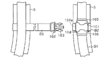
- Patent Document 1 describes a configuration as shown in FIG.
- the chest stop includes belt-like bodies B1 and B2 attached to one shoulder belt S, a cross-type female buckle 101 attached by crossing the belt-like bodies B1 and B2, and a belt-like body attached to the other shoulder belt S. It consists of a body B3 and a male buckle 102 attached to the strip-shaped body B3.
- the female buckle 101 and the male buckle 102 are made of resin, and are inserted into and engaged with the insertion opening 104a provided in the main body 104 of the female buckle 101 while bending the insertion leg portion 103 of the male buckle 102. 102 and the male buckle 102 are connected.
- the female buckle 101 includes a through portion 105 through which the vertically extending strip B1 passes and a through portion 106 through which the horizontally extending strip B2 passes.
- a straight type which can attach only one strip
- the female buckle 101 since the female buckle 101 is configured to receive the entire insertion leg portion 103 of the male buckle 102, the thickness of the main body 104 of the female buckle 101 needs to be greater than the thickness of the insertion leg portion 103. It was. Further, in the cross type female buckle 101, since the through portion 106 is provided below the main body 104, the entire female buckle is enlarged in the thickness direction. For this reason, the female member of the buckle is required to be downsized for the purpose of reducing the weight and improving the aesthetic appearance.
- a buckle including a male member 110 having a first piece 115 and a second piece 117 and a female member 112 for receiving the first piece 115.
- the male member 110 and the female member 112 are provided with attachment portions 113 and 114 for attaching the strips B4 and B5 at their ends.
- the first piece 115 of the male member 110 to which the belt-like body B4 is attached is inserted into the insertion portion 116 of the female member 112.
- the second piece 117 of the male member 110 slides on the surface of the female member 112 in a bent state.
- the female member 112 of the buckle described in Patent Document 2 can be downsized in the height direction, but recently, downsizing is also required in the width direction.
- the female member in the case where the female member has a configuration for attaching the strips so as to cross each other, it is necessary to provide a plurality of attachment portions through which one strip-like member is inserted. In other words, the female member is enlarged accordingly.
- the present invention has been made in view of the above problems, and an object of the present invention is to provide a buckle capable of reducing the size of a female member.
- the present invention includes a female member to which a belt-like body is attached, a first piece portion, and a second piece portion, and the first piece portion and the second piece portion are bent by the second piece portion.
- a buckle comprising a male member configured to receive a part of the female member between second pieces, wherein the female member is inserted through at least one band-shaped body, A slot portion into which the first piece portion can be inserted, and an engagement portion that engages with an engaging portion provided in the second piece portion when the first piece portion of the male member is inserted into the slot portion. And having a joint part.
- the female member can insert the belt-like body and the first piece of the male member into the slot portion, the attachment portion for attaching the belt-like body inserted through the slot portion to the female member, It is not necessary to be provided so as to protrude from the side surface of the female member. For this reason, a female member can be reduced in size in the width direction.
- the female member is fastened to the male member by receiving a part of the female member between the first piece and the second piece of the male member.
- the female member can be made thinner than a buckle having a conventional configuration housed in the member. Therefore, it is possible to reduce the size of the female member.
- the female member includes an attachment portion for inserting another belt-like body in a state of intersecting the belt-like body inserted through the slot portion.
- the position of the female member attached to the accessory or the like is not easily displaced, and the male member is easily fastened or released to the female member.
- the female member since the female member has both a configuration in which the strips are inserted to cross each other and a configuration in which the male member is fastened, the male member and the male member that allow the strips to be allowed to pass through, for example, accessories are inserted. It is not necessary to provide both of the members for fastening the members, and the number of parts can be reduced.
- the female member includes a first opening for inserting the first piece portion and the belt-like body into the slot portion, and a first opening provided in parallel to the first opening and passing through the belt-like body. 2 openings are preferably provided.
- the belt-like body can be inserted without being bent in the slot portion. For this reason, thickness reduction of the female member by which the strip
- the female member has a plurality of openings into which the first piece part and the belt-like body can be inserted in the slot part.
- the male member can be inserted from a plurality of directions. For this reason, the freedom degree of a buckle can be improved.
- a protrusion that guides the first piece of the male member is provided on a side surface of the slot portion.
- the first piece can be inserted into the slot while positioning. For this reason, even if the height of the slot portion into which the first piece portion is inserted is reduced by thinning the female member, the first piece portion is not caught in the belt-like body, and the first piece portion is inserted into the slot portion. Can be inserted smoothly.
- a round portion is provided on a side surface of the slot portion into which the first piece portion and the belt-like body are inserted, and opposite to the end face of the first piece portion and the belt-like body.
- the first piece of the male member can be easily received even when the belt-like body is inserted through the slot.
- the side surface of the slot portion which is provided on the opening side of the slot portion of the surface that contacts the first piece portion when the male member is inserted, faces the insertion direction of the male member. It is preferable that at least one of an inclined surface inclined and an inclined surface provided at a tip of the first piece of the male member and inclined toward the insertion direction of the male member is provided.
- the male member can be inserted into the female member while gradually bringing the opening side of the slot portion into contact with the first piece portion. That is, even if the angle at which the male member is inserted is oblique to the central axis of the slot portion, the male member can be smoothly inserted.
- the female member according to the present invention is notched inward from an opening through which the first piece and the belt-like body can be inserted, and includes a notch for receiving the male member, and the notch is formed. It is preferable that the end face is recessed around the notch. In this case, when the male member is inserted into the female member, the male member can be guided in the direction of the notch.
- the top view of the buckle of the fastening state which comprises a chest strap.
- the perspective view of the female member of the buckle. (A) is a side view of the buckle, (b) is a plan view of the buckle. (A) is a bottom view of the buckle, (b) is a bottom view of the buckle through which a horizontal tape is inserted.
- the perspective view of the male member of the buckle The side view of the male member of the buckle.
- (A) is a state in which the male member of the buckle is inserted into the notch
- (b) is a state in which the engaging portion of the male member slides on the inclined surface
- (c) is an engaged portion of the female member in the engaging portion.
- (A) is a top view of the female member of the buckle
- (b) is a side view of the female member.
- the top view which shows the buckle of the fastening state of 2nd Embodiment which actualized this invention.
- the top view which shows the buckle which comprises the conventional chest strap.
- the buckle of the present invention is embodied as a buckle constituting a chest strap of a backpack
- the buckle of this embodiment is a cross-type buckle that is attached to a female member by crossing a pair of strips.
- the buckle includes a female member 11 to be attached in a state where the horizontal tape 12 and the vertical tape 13 as a band-shaped body intersect with each other, and a male member 15 to which the adjustment tape 14 is attached.
- the horizontal tape 12 is stretched so that its longitudinal direction is parallel to the width direction (short direction) of the shoulder belt S, and its end is fixed to the shoulder belt S.
- the longitudinal tape 13 is stretched so that its longitudinal direction is parallel to the longitudinal direction of the shoulder belt S, and its end is fixed to the shoulder belt S.
- the vertical tape 13 is stretched in a state in which the edge parallel to the longitudinal direction is not fixed to the shoulder belt S, so that it can fix other types of buckles or the like for attaching a mountain climbing tool or the like. It has become.
- one end of the adjustment tape 14 to which the male member 15 is fixed is fixed to the other shoulder belt (not shown).
- the tape length from the tape edge part fixed to the other shoulder belt to the male member 15 is adjusted by changing the tape length pulled out from the male member 15.
- the male member 15 whose tape length is adjusted is fastened to the female member 11 fixed to the shoulder belt S, so that the backpack is fitted to the user's body.
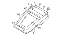
- the female member 11 As shown in FIG. 2, the female member 11 is formed in a flat shape and has a rectangular shape in plan view.
- a first slot 20 for inserting the horizontal tape 12 is formed inside the female member 11.
- the first slot portion 20 includes an opening 21 on the right end surface 11 b of the female member 11.
- a corner R portion 23 is formed at a corner portion on the opening 21 side constituting the first slot portion 20.
- the female member 11 also has an opening 22 in the left end surface 11c.
- the opening 22 is provided in parallel to the opening 21 of the right end surface 11b.
- the horizontal tape 12 is inserted into the first slot portion 20 through the openings 21 and 22.
- the female member 11 includes a pair of vertical tape attachment portions 24 on both side surfaces thereof.
- the vertical tape attachment portion 24 includes a first hook 24a that is formed in a substantially L shape from the side surface of the female member 11, and a second hook 24b that is provided in the same straight line as the first hook 24a.
- a second slot portion 25 into which the vertical tape 13 can be inserted is provided between the first hook 24a and the second hook 24b, and the end surfaces on the gap side of the first hook 24a and the second hook 24b are inclined surfaces. ing.
- the vertical tape 13 can be inserted into the second slot portion 25 from the side of the vertical tape attachment portion 24 through this gap. Further, the end surfaces of the first hook 24 a and the second hook 24 b are inclined surfaces, so that the vertical tape 13 can be easily inserted into the second slot portion 25.
- the first slot portion 20 is opened through the bottom surface side opening 11e.
- the vertical tape 13 is inserted from the flat surface of the female member 11 toward the bottom surface in the vertical tape mounting portion 24 located at the upper side in the drawing, and the female side so as to close the bottom surface side opening 11e.
- a vertical tape mounting portion 24 that crosses the bottom surface of the member 11 and is located downward in the drawing is inserted from the bottom surface of the female member 11 toward the plane.
- the female member 11 includes a cutout portion 27 that is cut out inward from the opening 21 side in the upper wall portion 26.
- An inclined surface 28 that is inclined toward the opening 21 side is formed at the end portion of the cutout portion 27.
- inclined surfaces 29 that expand toward the opening 21 are formed on both sides of the cutout portion 27 on the back surface of the upper wall portion 26.
- the inclined surface 29 is inclined in the insertion direction of the male member 15.
- the end surface 11 r on the opening 21 side of the female member 11 is a curved surface that is recessed with the notch 27 as the center. The end surface 11r is curved along a gentle arc CL and is most recessed at the position of the notch 27.
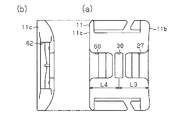
- the engaged portion 30 is formed through the upper wall portion 26 in the vicinity of the notch portion 27.
- the widths of the cutout portion 27, the inclined surface 28, and the engaged portion 30 are formed to be substantially the same, and are formed in a line in parallel with the insertion direction of the horizontal tape 12 (Y-axis direction in the drawing).
- a locking projection 31 is formed on the back surface of the upper wall portion 26 and in a direction opposite to the direction from the engaged portion 30 toward the cutout portion 27 (Y-axis direction in the drawing).
- each protrusion 32 is formed on the back surface of the upper wall portion 26 and on both sides of the locking protrusion 31. As shown in FIG. Each protrusion 32 is formed such that its longitudinal direction is parallel to the insertion direction of the horizontal tape 12 and the male member 15 (Y-axis direction in the figure). An inclined surface 32 a is formed at the tip of the protrusion 32 on the opening 21 side of the first slot portion 20.
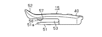
- the male member 15 includes an adjustment tape attachment portion 40, and the adjustment tape attachment portion 40 has a first insertion hole 41 and a second insertion hole 42.
- the first insertion hole 41 and the second insertion hole 42 are formed to penetrate from the upper surface of the male member 15 toward the lower surface.
- an inclined surface 41 a that is inclined toward the lower surface of the male member 15 is formed on the right end surface 15 a side of the first insertion hole 41.
- the adjusting tape 14 passes from the lower opening of the first insertion hole 41 through the upper opening and passes from the upper opening of the second insertion hole 42 toward the lower opening.
- the adjustment tape 14 drawn out from the second insertion hole 42 is extended in parallel with the adjustment tape 14 drawn out from the first insertion hole 41 on the bottom surface side of the male member 15.
- the male member 15 includes a first piece 51 and a second piece 52 that are formed to extend from the adjustment tape attachment portion 40. As shown in FIG. 6, the first piece 51 and the second piece 52 are provided in parallel via a space 53.
- the male member 15 is fixed to the female member 11 in a state where a part of the cutout portion 27 and the upper wall portion 26 of the female member 11 is sandwiched between the spaces 53. That is, the first slot portion 20 of the female member 11 is formed at a height that can receive the second piece portion 52 of the male member while the horizontal tape 12 is inserted.
- the first piece 51 is inserted into the first slot portion 20 of the female member 11, and the second piece 52 is fixed to the surface of the upper wall portion 26 of the female member 11.
- the first piece 51 is formed in a substantially flat plate shape, and has an inclined surface 51 a that is inclined toward the lower surface of the male member 15 at the tip thereof. That is, the inclined surface 51 a is inclined toward the insertion direction into the female member 11. Moreover, as shown in FIG. 7, the 1st piece part 51 has the through-hole 51b in the center.
- the length L1 of the first piece 51 is the length L2 from the opening 21 of the female member 11 shown in FIG. 4A to the tip of the locking projection 31 provided in the first slot portion 20. It is almost the same.
- the width W1 of the 1st piece part 51 shown in FIG. 7 is substantially the same as the width W2 between each protrusion 32 shown to Fig.4 (a). That is, the first piece portion 51 is inserted in the first slot portion 20 and between the protrusions 32, and the tip of the first piece portion 51 is slidable to contact with the locking protrusion 31.
- the second piece 52 is provided with a concave portion 55 on its upper surface and an operation portion 56 formed so as to warp upward at the tip.
- the recess 55 is formed to have almost the same size as the index finger or the fingertip of the thumb.
- a substantially plate-like engagement portion 57 is formed to protrude from the back surface of the second piece portion 52.
- the engaging portion 57 is formed to be smaller than the height of the space 53, and the height of the gap provided between the engaging portion 57 and the first piece portion 51 is greater than the thickness of the upper wall portion 26 of the female member 11. Is also small.
- the engaging portion 57 is formed perpendicular to the back surface of the second piece portion 52 and extends in the width direction of the second piece portion 52.
- a rib 58 is formed from the side surface of the engaging portion 57 on the operation portion 56 side.
- the horizontal tape 12 is inserted into the first slot portion 20 through the openings 21 and 22 of the female member 11. Since the corner
- the opening 21 of the female member 11 through which the horizontal tape 12 and the vertical tape 13 are inserted is opposed to the tip of the first piece 51 of the male member 15 through which the adjustment tape 14 is inserted.
- the first piece 51 of the male member 15 is inserted into the first slot portion 20 of the female member 11 and above the horizontal tape 12.
- the end surface 11r of the female member 11 is a curved surface that is recessed with the notch 27 as a center. For this reason, when the male member 15 is inserted into the female member 11, even if the tip of the male member 15 deviates from the notch 27 and is pressed against the end surface 11r, the male member 15 is slid along the lateral direction of the end surface 11r. Thus, it can be guided in the direction of the notch 27.
- the male member 15 since the inclined surface 29 is provided on the opening side of the female member 11 and the inclined surface 51 a is provided on the first piece 51 of the male member 15, the male member 15 includes the first piece 51. It is inserted into the female member 11 while gradually contacting the inclined surface 29 of the female member 11. That is, the male member 15 is inserted obliquely with respect to the vertical direction with respect to the insertion direction of the male member 15 into the first slot portion 20 (the direction from one opening 21 of the slot portion 20 toward the other opening 22). Even in such a case, the male member 15 can be inserted smoothly.
- the 1st piece part 51 is guide
- the 1st slot part 20 is positioned. Further, the height of the opening 21 and the first slot portion 20 of the female member 11 is formed slightly longer than the sum of the thickness of the lateral tape 12 and the thickness of the first piece portion 51. For this reason, the 1st piece part 51 is inserted, without moving the horizontal tape 12 penetrated in the 1st slot part 20 unnecessarily. Moreover, since the inclined surface 32a is formed in the protrusion 32 and the corner
- the second piece 52 of the male member 15 is inserted into the notch 27 of the female member 11.
- the engaging portion 57 of the second piece 52 abuts on the inclined surface 28 provided at the end of the notch 27.
- the engaging portion 57 that has been in contact with the inclined surface 28 slides the inclined surface 28 toward the engaged portion 30, as shown in FIG. Move.
- the second piece 52 of the male member 15 bends so as to warp from the inclined surface 28.
- the first piece 51 slides on the back surface of the upper wall portion 26 of the female member 11 while being guided by the protrusion 32.
- the engaging portion 57 of the male member 15 reaches the top of the inclined surface 28.
- the engaging portion 57 reaches the position of the engaged portion 30 of the female member 11, the engaging portion 57 is engaged by the restoring force of the second piece portion 52 as shown in FIG.
- the male member 15 is inserted into the joint portion 30 and fastened to the female member 11. Even if it is attempted to pull out the male member 15 from the female member 11 without bending the second piece 52 by the engagement of the engaging portion 57 and the engaged portion 30, the engaging portion 57 and the engaged portion 30 It cannot be pulled out by engagement.
- a force in a direction of separating from the female member 11 is applied to the operation portion 56 of the male member 15.
- the back surface of the operation unit 56 is pressed with a finger, and the operation unit 56 is pressed away from the female member 11.
- the second piece 52 of the male member 15 is bent so as to be warped, and the engaging portion 57 of the male member 15 is extracted from the engaged portion 30 of the female member 11.
- the fastening is released by sliding the male member 15 away from the female member 11 while maintaining this state.
- the female member 11 is inserted through the horizontal tape 12 in a state where the horizontal tape 12 is flattened without being bent in the middle of the first slot portion 20, so that the mounting portion for attaching the horizontal tape 12 is a female member. There is no need to provide it below 11 or the like. Moreover, even if the space which allows the horizontal tape 12 to pass through is secured in the first slot portion 20 into which the first piece 51 of the male member 15 is inserted, the horizontal tape 12 has a thickness of about 1 mm or less. Since it is thin, the female member 11 is not enlarged in the height direction by providing the space. Therefore, the female member 11 can be downsized not only in the height direction but also in the width direction by an amount corresponding to the attachment portion of the lateral tape 12.
- the vertical tape 13 is provided with a buckle such as a so-called D-ring, and climbing equipment may be attached to the buckle, so that the climbing equipment is less likely to be caught on the female member 11.
- the female member 11 is configured such that a part of the upper wall portion 26 is received between the first piece 51 and the second piece 52 of the male member 15 so that the male member 15 Therefore, the female member 11 can be made thinner than a buckle having a conventional configuration in which the entire insertion portion of the male member 15 is accommodated in the female member. Moreover, since the female member 11 can insert the horizontal tape 12 and the first piece 51 of the male member 15 into the first slot portion 20, the mounting portion for attaching the horizontal tape 12 to the female member 11 is a female member. 11 is not required to be provided so as to protrude from 11. For this reason, the female member 11 can be reduced in size in the width direction parallel to the longitudinal direction of the horizontal tape 12.
- the female member 11 since the female member 11 is fixed in a state where the horizontal tape 12 and the vertical tape 13 are crossed, the position of the female member 11 is difficult to shift on the shoulder belt S of the backpack. 15 is easily fastened or released to the female member 11.
- the cross-type female member of the conventional configuration is easy to increase in size because a plurality of attachment portions for attaching one band-like body are provided on the side surface and the bottom surface, but in the first embodiment, the first of the female member 11 is the first. Since the horizontal tape 12 is inserted into the slot portion 20, the effect can be exhibited particularly in terms of thinning.
- the first slot portion 20 includes the openings 21 and 22 through which the horizontal tape 12 is inserted in parallel, so that the horizontal tape 12 is inserted without being bent in the first slot portion 20. it can. For this reason, the space occupied by the horizontal tape 12 in the first slot portion 20 can be minimized. Moreover, since the horizontal tape 12 is not pulled out from the surface of the female member 11, but pulled out from the right end surface 11b and the left end surface 11c, the height of the buckle including the tape can be lowered.
- the corner R on the opening side of the first slot portion 20 is provided with the corner R portion 23, so that the lateral tape 12 can be easily received. Moreover, even if the horizontal tape 12 is inserted through the first slot portion 20, the first piece portion 51 of the male member 15 can be easily received.
- the protrusion 32 which can clamp the 1st piece part 51 of the male member 15 is provided in the side surface of the 1st slot part 20, the 1st piece part 51 is made into 1st. It can be inserted while positioning in the slot portion 20. For this reason, the space for inserting the first piece 51 can be minimized. Further, when the first piece 51 is inserted into the first slot portion 20, the horizontal tape 12 inserted through the first slot portion 20 is not displaced or twisted.
- the female member 11 has the inclined surface 29 inclined toward the insertion direction of the male member 15 on the back surface of the upper wall portion 26 of the first slot portion 20. Further, an inclined surface 51 a that is inclined toward the insertion direction of the male member 15 is provided at the tip of the first piece 51 of the male member 15. For this reason, when inserting the male member 15 into the female member 11, the male member 15 can be inserted while gradually bringing the opening side of the first slot portion 20 into contact with the first piece portion 51. That is, even if the angle at which the male member 15 is inserted is oblique to the central axis of the first slot portion 20, the male member 15 can be inserted smoothly.
- the female member 11 is provided with an end surface 11r that is recessed around the notch 27 that receives the male member 15. Therefore, when the male member 15 is inserted into the female member 11, the male member 15 can be guided in the direction of the cutout portion 27, so that operability when the male member 15 is inserted into the female member 11 is improved. Can do.
- the female member 11 is formed on both sides of the engaged portion 30 so as to be cut out from the notch 27 described in the first embodiment and the left end surface 11c.
- the cutout portion 60 is provided.
- the notch 60 is formed in the same shape as the notch 27 on the right side in the drawing. Further, the distance L3 from the engaged portion 30 to the right end surface 11b and the distance L4 from the engaged portion 30 to the left end surface 11c are the same.
- the left end surface 11c of the female member 11 has an opening 62 having the same shape as the opening 21 formed on the right end surface. That is, the horizontal tape 12 and the first piece 51 of the male member 15 described in the first embodiment can be inserted into the opening 62.
- This female member 11 is not only capable of inserting the male member 15 from the notch 27 as described in the first embodiment, but also from the notch 60 formed on the left end surface as shown in FIG. 15 can be inserted. That is, the female member 11 has a configuration in which the male member 15 can be inserted from both sides.
- the female member 11 is provided with the openings 21 and 62 into which the first piece 51 of the male member 15 and the lateral tape 12 can be inserted in the first slot portion 20. Can be inserted from multiple directions. For this reason, the freedom degree of a buckle can be improved.
- both the inclined surface 29 of the female member 11 and the inclined surface 51a of the male member 15 are provided.
- the male member 15 can be smoothly inserted into the female member 11.
- the buckle of the present invention is embodied as a cross type buckle, but may be embodied as a straight type buckle.
- the female member 11 has a configuration in which the vertical tape attachment portion 24 is omitted.
- the female member 11 can be downsized also in the width direction of the horizontal tape 12.
- a pair of cutout portions 27 and 60 are provided and only one engaged portion 30 is formed.
- the engaged portion 30 adjacent to one cutout portion 27 and the other cutout portion 27 are formed.
- the female member 11 may be provided with an engaged portion adjacent to the female member 11.
- the buckle is embodied as a buckle constituting a chest strap, but may be embodied as a buckle used for other accessories.
- the entire contents of the specification, claims, drawings, and abstract of Japanese Patent Application No. 2011-077740 filed on March 31, 2011 are incorporated herein as the disclosure of the specification of the present invention. Is.
Landscapes
- Buckles (AREA)
Abstract
L'invention concerne une boucle obtenue à partir d'un élément femelle (11), sur lequel sont installées une bande transversale (12) et une bande longitudinale (13), et d'un élément mâle (15) possédant une première plaque (51) et une seconde plaque (52) et configuré de telle sorte que lors de la flexion de la seconde plaque (52) une partie de l'élément femelle soit reçue entre la première plaque (51) et la seconde plaque (52). L'élément femelle (11) possède une première fente (20) dans laquelle peut être insérée la première plaque (51) de l'élément mâle (15) lorsque la bande transversale (12) est insérée, et une partie destinée à entrer en prise (30) avec laquelle vient en prise une partie d'entrée en prise (57) située sur la seconde plaque (52) lorsque la première plaque (51) de l'élément mâle est insérée dans la première fente (20).
Priority Applications (1)
| Application Number | Priority Date | Filing Date | Title |
|---|---|---|---|
| CN201280026214.5A CN103582435B (zh) | 2011-03-31 | 2012-03-30 | 带扣 |
Applications Claiming Priority (2)
| Application Number | Priority Date | Filing Date | Title |
|---|---|---|---|
| JP2011077740A JP5851109B2 (ja) | 2011-03-31 | 2011-03-31 | バックル |
| JP2011-077740 | 2011-03-31 |
Publications (1)
| Publication Number | Publication Date |
|---|---|
| WO2012133806A1 true WO2012133806A1 (fr) | 2012-10-04 |
Family
ID=46931500
Family Applications (1)
| Application Number | Title | Priority Date | Filing Date |
|---|---|---|---|
| PCT/JP2012/058642 Ceased WO2012133806A1 (fr) | 2011-03-31 | 2012-03-30 | Boucle |
Country Status (3)
| Country | Link |
|---|---|
| JP (1) | JP5851109B2 (fr) |
| CN (1) | CN103582435B (fr) |
| WO (1) | WO2012133806A1 (fr) |
Families Citing this family (2)
| Publication number | Priority date | Publication date | Assignee | Title |
|---|---|---|---|---|
| JP6462510B2 (ja) * | 2015-06-26 | 2019-01-30 | Ykk株式会社 | バックル |
| DE102021213558B3 (de) * | 2021-11-30 | 2023-02-16 | Fidlock Gmbh | Verbindungsvorrichtung |
Citations (5)
| Publication number | Priority date | Publication date | Assignee | Title |
|---|---|---|---|---|
| JPS6399509U (fr) * | 1986-12-18 | 1988-06-28 | ||
| JPH08103304A (ja) * | 1994-10-05 | 1996-04-23 | Nifco Inc | バックルの固定構造 |
| JP2000000106A (ja) * | 1998-06-16 | 2000-01-07 | Nifco Inc | バックル |
| JP2005160687A (ja) * | 2003-12-02 | 2005-06-23 | Nifco Inc | サイドリリースタイプのバックル、および、リュックサック |
| JP2009285042A (ja) * | 2008-05-28 | 2009-12-10 | Nifco Inc | バックル |
Family Cites Families (2)
| Publication number | Priority date | Publication date | Assignee | Title |
|---|---|---|---|---|
| US5084946A (en) * | 1990-12-11 | 1992-02-04 | Indiana Mills & Manufacturing, Inc. | Quick disconnect connector |
| JPH073320U (ja) * | 1993-05-07 | 1995-01-20 | ワイケイケイ株式会社 | バックル |
-
2011
- 2011-03-31 JP JP2011077740A patent/JP5851109B2/ja active Active
-
2012
- 2012-03-30 CN CN201280026214.5A patent/CN103582435B/zh active Active
- 2012-03-30 WO PCT/JP2012/058642 patent/WO2012133806A1/fr not_active Ceased
Patent Citations (5)
| Publication number | Priority date | Publication date | Assignee | Title |
|---|---|---|---|---|
| JPS6399509U (fr) * | 1986-12-18 | 1988-06-28 | ||
| JPH08103304A (ja) * | 1994-10-05 | 1996-04-23 | Nifco Inc | バックルの固定構造 |
| JP2000000106A (ja) * | 1998-06-16 | 2000-01-07 | Nifco Inc | バックル |
| JP2005160687A (ja) * | 2003-12-02 | 2005-06-23 | Nifco Inc | サイドリリースタイプのバックル、および、リュックサック |
| JP2009285042A (ja) * | 2008-05-28 | 2009-12-10 | Nifco Inc | バックル |
Also Published As
| Publication number | Publication date |
|---|---|
| CN103582435A (zh) | 2014-02-12 |
| CN103582435B (zh) | 2017-03-15 |
| JP2012210343A (ja) | 2012-11-01 |
| JP5851109B2 (ja) | 2016-02-03 |
Similar Documents
| Publication | Publication Date | Title |
|---|---|---|
| US8769783B2 (en) | Buckle | |
| CN102361568B (zh) | 旁开扣 | |
| CN205125270U (zh) | 扣具 | |
| KR102037020B1 (ko) | 계지구를 구비한 마스크 | |
| KR101016882B1 (ko) | 스트랩 조절구 | |
| JP4143927B2 (ja) | バックル | |
| TWI528912B (zh) | buckle | |
| EP2622984B1 (fr) | Curseur pour fermeture à glissière | |
| CN109152454A (zh) | 绳扣 | |
| US8813321B2 (en) | Buckle | |
| JP5851109B2 (ja) | バックル | |
| JP5628585B2 (ja) | バックル | |
| CN108813831B (zh) | 拉链 | |
| US11766097B2 (en) | Buckle and buckle male part | |
| WO2015071945A1 (fr) | Chaîne de fermeture, et fermeture à glissière | |
| JP5538074B2 (ja) | バックル | |
| CN104939445B (zh) | 用于拉链的拉头 | |
| KR20050072698A (ko) | 버클 및 배낭 | |
| JPH11342008A (ja) | 着脱可能な雌雄型バックル | |
| HK1176831B (en) | Buckle | |
| TWM520287U (zh) | 扣具 |
Legal Events
| Date | Code | Title | Description |
|---|---|---|---|
| 121 | Ep: the epo has been informed by wipo that ep was designated in this application |
Ref document number: 12765498 Country of ref document: EP Kind code of ref document: A1 |
|
| NENP | Non-entry into the national phase |
Ref country code: DE |
|
| 122 | Ep: pct application non-entry in european phase |
Ref document number: 12765498 Country of ref document: EP Kind code of ref document: A1 |