WO2012133822A1 - Élément métallique en forme de colonne creuse - Google Patents
Élément métallique en forme de colonne creuse Download PDFInfo
- Publication number
- WO2012133822A1 WO2012133822A1 PCT/JP2012/058681 JP2012058681W WO2012133822A1 WO 2012133822 A1 WO2012133822 A1 WO 2012133822A1 JP 2012058681 W JP2012058681 W JP 2012058681W WO 2012133822 A1 WO2012133822 A1 WO 2012133822A1
- Authority
- WO
- WIPO (PCT)
- Prior art keywords
- vertex
- angle
- portions
- section
- hollow columnar
- Prior art date
- Legal status (The legal status is an assumption and is not a legal conclusion. Google has not performed a legal analysis and makes no representation as to the accuracy of the status listed.)
- Ceased
Links
Images








Classifications
-
- B—PERFORMING OPERATIONS; TRANSPORTING
- B62—LAND VEHICLES FOR TRAVELLING OTHERWISE THAN ON RAILS
- B62D—MOTOR VEHICLES; TRAILERS
- B62D21/00—Understructures, i.e. chassis frame on which a vehicle body may be mounted
- B62D21/02—Understructures, i.e. chassis frame on which a vehicle body may be mounted comprising longitudinally or transversely arranged frame members
-
- B—PERFORMING OPERATIONS; TRANSPORTING
- B62—LAND VEHICLES FOR TRAVELLING OTHERWISE THAN ON RAILS
- B62D—MOTOR VEHICLES; TRAILERS
- B62D21/00—Understructures, i.e. chassis frame on which a vehicle body may be mounted
- B62D21/15—Understructures, i.e. chassis frame on which a vehicle body may be mounted having impact absorbing means, e.g. a frame designed to permanently or temporarily change shape or dimension upon impact with another body
Definitions
- the present invention relates to a thin-walled hollow columnar member made of metal such as steel, aluminum, stainless steel, titanium or the like constituting the frame.
- an energy absorbing member whose main deformation mode is the axial crushing deformation mode such as a crash box, is required to be a member that does not change its shock absorption capacity greatly due to a certain change in boundary conditions, that is, has excellent robustness. It is done.
- the strength balance refers to the distribution in the longitudinal direction, such as the secondary moment of inertia and the maximum buckling load calculated from the cross-sectional shapes perpendicular to the longitudinal direction of the frame and the applied material properties.
- the energy absorption amount per crushing amount in the unit axis direction is referred to, and the robustness is the invariance of the shock absorption ability with respect to the change of the dynamic boundary condition.
- Patent Document 1 discloses a shock absorbing member that forms a groove section that is a closed section having a plurality of vertices in a cross-sectional shape in at least a part in the axial direction, and is recessed toward the inside. .
- Patent Document 2 describes a technique of providing a convex portion having a rectangular cross section outside a wall surface portion in an energy absorbing member made of an aluminum alloy extruded member having a hollow rectangular cross section.
- Patent Document 3 discloses a front side frame of an automobile in which a bead having an inward convex shape and a bead having a convex shape outward are formed extending in the axial direction on a side surface.
- Patent Document 4 describes a shock absorbing member for an automobile having a substantially C-shaped cross section with an opening facing outward in the vehicle width direction.
- Patent Document 5 in the impact absorbing member having a polygonal cross section, the length of one side having a polygonal cross section, the length of two adjacent sides across the side, and the range of angles formed by the two sides A technique for limiting the above is described.
- Patent Documents 1 to 3 all of the techniques disclosed in Patent Documents 1 to 3 increase the total number of apexes of the cross section and remarkably improve the cross-sectional force per unit length of the member due to compressive deformation by forming an extremely uneven portion. Therefore, it is necessary to redesign the frame as a whole from the viewpoint of the strength balance of the frame. When applied partially, there is a risk that the overall strength balance may be lost, and the impact energy absorption amount of the member itself may be reduced due to deformation from an unexpected location. Furthermore, since extreme uneven part forming destabilizes the deformation mode, there is a risk that stable axial deformation is difficult.
- An object of the present invention is to provide a technique for improving the shock absorbing ability without impairing the strength balance and an applied member thereof.
- the behavior of the apex portion of the cross section of the member becomes the energy absorption amount during crushing deformation. I found that it contributed greatly. If the apex portion before crushing deformation disappears due to deformation such as bending during crushing deformation, the reaction force is significantly reduced. Therefore, a method that does not cause bending at the apex portion is effective, but control is particularly difficult during axial crushing deformation. Therefore, the present inventors have found that the disappearance of the apex portion during crushing deformation can be suppressed by controlling the bending position by crushing analysis and experiment in the axial direction of the member. Since this technique reduces the rate of reaction force reduction due to buckling, the overall strength balance is not impaired.
- a metal hollow columnar member having a polygonal cross section having at least five apexes and sides extending between the apexes, the polygonal cross section having an inner corner.
- Two small vertices (A, B) divide the perimeter into two perimeter segments of one or more sides, at least one of the two perimeter segments including at least four sides, the at least four
- the internal angle of the vertex portion (C) having the smallest internal angle in (i) is larger than the internal angle of the two vertex portions (A, B), and along the surrounding segment including the at least four sides, the at least 3 Between the vertex portion (C) having the smallest interior angle and one of the two vertex portions (A, B) (A) of the two vertex portions ⁇ (i), and the vertex having the smallest interior angle A vertex portion having an inner angle larger than the inner angle of the vertex portion (C) having the smallest inner angle between the portion (C) and the other (B) of the two vertex portions (A, B) A metal hollow columnar member in which (VI) is present is provided.
- a metal hollow columnar member having a polygonal cross section having at least five apex portions and sides extending between the apex portions,
- the hollow columnar member is provided with two joints (J), and the polygonal cross section is surrounded by two apexes (A, B) in the vicinity of the two joints (J), and the periphery thereof is one or more sides.
- a metal hollow columnar member in which an apex (VI) having an internal angle larger than the internal angle of the apex (C) having the minimum
- the metal hollow columnar member of the present invention is particularly suitable for a frame member constituting an automobile frame.
- the polygon means that the figure formed by the intersection of the straight lines extending each side is a polygon, and the metal hollow columnar member having a polygonal cross section is at the apex.
- a member having a curvature is included.
- a member having improved shock absorption and robustness without impairing the strength balance is provided.
- FIG. 1 It is a schematic diagram which shows the surrounding segment of the polygon cross section of the hollow columnar member which is an example of this invention. It is the figure which showed an example of the surrounding segment of the polygon cross section of this invention, Comprising: One point on the substantially polyline along a substantially polygon between two vertex parts A and C and between two vertex parts B and C It is explanatory drawing which shows typically the cross section of the hollow columnar member before a bending
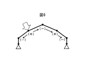
- (+) indicates a vertex portion having an interior angle larger than the interior angles of adjacent vertex portions among the vertex portions between points A and b
- ( ⁇ ) indicates one of the vertex portions between points A and b.
- the vertex part of the inner angle smaller than the inner angle of the vertex part of the neighbor and / or both neighbors is shown.
- (+) indicates a vertex portion between the points A ′ and B ′, and has an interior angle larger than the interior angle of one of the adjacent vertex portions and / or both adjacent vertex portions
- ( ⁇ ) indicates the points A ′ and B ′.
- the vertexes between ′ the vertexes having an inner angle smaller than the inner angles of the adjacent vertexes are shown.
- the inventors of the present invention have shown that (a) the increase in reaction force during crushing is mainly influenced by the number of apexes of the cross-sectional shape of the member before deformation, according to the axial crush analysis and experiment of the member. (B) Decrease in reaction force at the time of crushing is influenced by the number of apexes of the cross-sectional shape of the member being deformed, (c) Increase in reaction force increases the maximum reaction force of the member, and so on. It has been found that the reduction of the reaction force does not affect other adjacent members because the maximum reaction force of the member does not change.
- the apex of the polygonal cross section may generally disappear due to bending during crushing. In that case, the member will be deformed with a cross-sectional shape having fewer apexes than the total number of initial apexes.
- the apex portion of the cross section disappears, the length of the side of the polygonal cross section becomes long, so that the buckling cycle becomes long. Since the buckling period corresponds to the fluctuation period of the reaction force, the number of reaction force peaks during crushing decreases as the buckling period increases.
- increasing the number of apexes of the polygonal cross section can increase the maximum reaction force of the member before buckling starts, but increasing the number of apexes of the polygonal cross section increases the internal angle of the apex. Therefore, the member is easily bent, and the reaction force of the member after buckling may be significantly reduced.
- the hollow columnar member having a polygonal cross section is inevitably bent due to the collapse, how to bend it is important in order to improve the shock absorbing performance of the member. Further, since bending causes a reduction in reaction force, by controlling the bending, there is a possibility that the number of apexes disappearing at the time of deformation can be reduced, and thus the amount of reduction in reaction force can be controlled.
- the present inventors by analysis and experiment of the crushing of the hollow columnar member having a polygonal cross-section, it is possible to suppress the disappearance of the apex portion by controlling the bending position, rather than reducing the number of bending, Furthermore, we found that the internal angle of the apex is an important factor for controlling the bending position.
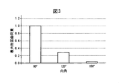
- the hollow columnar member becomes easier to bend as the inner angle of the apex portion in the cross section is larger.
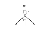
- the apex coupling portion is indicated by an arrow F.
- the maximum bending load immediately before the start of bending can be analyzed in terms of material mechanics.
- the maximum bending load is very sensitive to the inner angle of the apex. Therefore, the deformation mode of the hollow columnar member having the polygonal cross section can be controlled and the robustness thereof can be improved by making the sizes of the respective inner angles of the apexes of the polygonal cross section appropriate.
- the present invention is applicable to a hollow columnar member having a polygonal cross section having at least five apexes.
- the position in the polygonal cross section where the bending occurs and the apex disappears depends on the load direction at the time of crushing, but mainly depends on the size and position of the inner angle of the apex and the presence of a joint such as a flange. It is determined.
- the material has excellent strength and ductility and retains a certain degree of ductility even in a complex stress state, that is, it is important that the anisotropy is small.
- the columnar member is preferably made of metal.
- the hollow columnar member having a polygonal cross section is preferably sized so as to be “compact” crushing deformation in the axial direction.
- the ratio (t / D) between the distance D between the apexes of the polygonal section and the thickness t is preferably 0.005 or more, and more preferably 0.010 or more.
- the ratio (h / H) between the length H in the longitudinal direction of the hollow columnar member and the minimum length h of the polygonal cross section is preferably 0.10 or more, and more preferably 0.15 or more.
- the minimum length of the polygonal cross section is the minimum distance between two parallel straight lines in contact with the cross section of the hollow columnar member.
- cohesive type refers to a deformation mode in which crushing is performed by repeating a certain pattern during axial crushing deformation, and has been referred to in a plurality of past documents.
- a first embodiment of the present invention will be described.
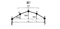
- two vertex portions A and B having a small inner angle are selected, and the two vertex portions A and B Divide the perimeter of the polygonal cross section into two perimeter segments consisting of one or more sides.
- the two vertex portions A and B are selected so that at least one of the two surrounding segments includes at least four sides.
- L be a straight line connecting the two vertex portions A and B
- S be the length of the straight line L, that is, the distance between the two vertex portions A and B.
- SS (i) ⁇ 0.5S that is, the interior angle is larger than 90 ° and the interior angles of the apex portions ⁇ (i) in the polygonal cross section are all 180 ° or less (FIG. 7)
- the vertex There is a high possibility that all or part of the apex portion ⁇ (i) on the peripheral segment between the portions A and B disappears due to bending.
- At least three vertex portions ⁇ (i) include a vertex portion having an internal angle of 180 ° or more, the side extends from the vertex portion, so that the hollow columnar member is crushed. At this time, the apex portion having an internal angle of 180 ° or more is deformed greatly differently from other apex portions, so that the deformation of the hollow columnar member during the crushing deformation becomes complicated, and the deformation control becomes difficult. Become.
- the inner angle of the vertex portion C having the smallest inner angle among the vertex portions ⁇ (i) is larger than the inner angles of the two vertex portions A and B.
- the vertex portion VI is designated as the vertex portion VI.
- ⁇ A ⁇ C ⁇ VI and ⁇ B ⁇ C ⁇ VI are the interior angle of the vertex portion A
- ⁇ B is the interior angle of the vertex portion B
- ⁇ C is the interior angle of the vertex portion C
- ⁇ VI is the interior angle of the vertex portion VI.
- the inner angle of the vertex C ′ is at least three of the vertexes A ′ and B ′ along the surrounding segment.
- the number of vertex portions disappearing due to bending when the hollow columnar member is crushed increases, and in the example of FIG. 9, the vertex portions A ′ and B ′.
- the apex portions ⁇ 1 and ⁇ 2 disappear, and as a result, the reaction force of the hollow columnar member is significantly reduced.
- the difference between the inner angles of the vertex portion VI and the vertex portion C is larger, preferably 10 °, more preferably 20 °.
- the plurality of vertex portions C are adjacent to each other. If they are not adjacent, that is, if the two points having a small inner angle in FIG. 9 are the apex portion C, as shown in FIG.
- the relationship between the vertex portions A, B, C, and VI is satisfied at least at a part of the cross section of the hollow columnar member, and may not be satisfied at all the vertices of the cross section. Good. For example, even if the part has a longitudinal bead of the member and the internal angle of a part of the apex of the cross section is 180 ° or more, if the internal angle relationship of the present invention is satisfied in the other part, A reduction in reaction force that fluctuates due to deformation is suppressed.
- the bending position in the polygon section can be controlled, and as a result, the number of disappearances of the top section can be suppressed.
- the hollow columnar member has two joint portions J such as flanges
- the joint portion J has a large thickness due to the overlapping of the plates, and therefore the apex portions A and B of the cross section closest to the two joint portions J are Difficult to disappear due to bending.
- L is a straight line connecting the two vertex portions A and B, the length of the straight line L, that is, the distance between the two vertex portions A and B is S, and at least three of the surrounding segments including at least four sides are included.
- At least three vertex portions ⁇ (i) include a vertex portion having an internal angle of 180 ° or more, the side extends from the vertex portion, so that the hollow columnar member is crushed. At this time, the apex portion having an internal angle of 180 ° or more is deformed greatly differently from other apex portions, so that the deformation of the hollow columnar member during the crushing deformation becomes complicated, and the deformation control becomes difficult. Become.
- the inner angle of the vertex portion C having the smallest inner angle among the vertex portions ⁇ (i) is larger than the inner angles of the two vertex portions A and B.
- the vertex portion VI is designated as the vertex portion VI.
- ⁇ A ⁇ C ⁇ VI and ⁇ B ⁇ C ⁇ VI are the interior angle of the vertex portion A
- ⁇ B is the interior angle of the vertex portion B
- ⁇ C is the interior angle of the vertex portion C
- ⁇ VI is the interior angle of the vertex portion VI.
- the inner angle of the vertex C ′ is at least three of the vertexes A ′ and B ′ along the surrounding segment.
- the number of vertex portions disappearing due to bending when the hollow columnar member is crushed increases, and in the example of FIG. 9, the vertex portions A ′ and B ′.
- the apex portions ⁇ 1 and ⁇ 2 disappear, and as a result, the reaction force of the hollow columnar member is significantly reduced.
- the difference between the inner angles of the vertex portion VI and the vertex portion C is larger, preferably 10 °, more preferably 20 °.
- the plurality of vertex portions C are adjacent to each other. If they are not adjacent, that is, if the two points having a small inner angle in FIG. 9 are the apex portion C, as shown in FIG.
- the relationship between the vertex portions A, B, C, and VI is satisfied at least at a part of the cross section of the hollow columnar member, and may not be satisfied at all the vertices of the cross section. Good. For example, even if the part has a longitudinal bead of the member and the internal angle of a part of the apex of the cross section is 180 ° or more, if the internal angle relationship of the present invention is satisfied in the other part, A reduction in reaction force that fluctuates due to deformation is suppressed.
- the bending position in the polygonal cross section can be controlled.
- the number of disappearances at the apex can be suppressed.
- the metal hollow columnar member of the present invention is particularly suitable for a frame member constituting an automobile frame.
- a frame member constituting an automobile frame.
- many designers and researchers have tackled many issues such as further improvement in collision safety performance, further weight reduction for improving fuel efficiency, and shortening the development period of many models for global expansion. It is out.
- the present invention is based on the distribution of the internal angle without changing the strength balance of the entire frame. Since collision safety is expected to improve, it is thought that the burden on the designer can be reduced and the vehicle weight can be reduced.
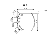
- FIGS. 12 and 13 the present inventors compared the relationship between the reaction force and the amount of crushing when crushing two types of thin hollow columnar members 100 and 200 having a substantially decagonal cross section.
- the dimensions of the cross-sectional shape are shown in FIG. 12 (member 100) and FIG. 13 (member 200).
- the member 200 is an example of the shape of the present invention.
- Both the members 100 and 200 are made of JSC590Y steel, have a length of 300 mm, a plate thickness of 1.6 mm, and a curvature of 1.35 mm ⁇ 1 is given to all corners.
- FIG. 15 member 300
- FIG. 16 member 400
- the member 400 is an example of the shape of the present invention.
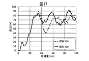
- Both members 300 and 400 are made of JSC590Y steel, have a length of 150 mm, a plate thickness of 1.6 mm, and a curvature of 1.35 mm ⁇ 1 is imparted to all corners.
- the relationship between the amount of crushing and the reaction force when an impact body with a weight of 700 kg is collided in the axial direction (direction perpendicular to the paper surface of FIGS. 15 and 16) and in the compression direction at an initial speed of 5.0 m / s is evaluated by analysis.
- the members 300 and 400 were compared (FIG. 17).
- the inventors of the present invention similarly changed the collision angle of the members 300 and 400 by 1 ° with respect to the axial direction of the members (inclined 1 ° to the right from the vertical direction in FIG. 15 and FIG. 16). Crush analysis was performed to confirm the influence of changes in the boundary condition between the crush amount and the reaction force (FIG. 18).
- the member of the present invention has an initial reaction force peak substantially the same as that of the outer member of the present invention, but suppresses a significant decrease in the reaction force when buckling from the initial reaction force peak.
- the relationship between the reaction force and the crushing amount is substantially equal, that is, the shock absorbing ability is approximately equal. It can be confirmed that the present invention can improve the impact absorption capability and the robustness while maintaining the maximum reaction force of the member equal.
Landscapes
- Engineering & Computer Science (AREA)
- Chemical & Material Sciences (AREA)
- Combustion & Propulsion (AREA)
- Transportation (AREA)
- Mechanical Engineering (AREA)
- Body Structure For Vehicles (AREA)
- Vibration Dampers (AREA)
- Rod-Shaped Construction Members (AREA)
Abstract
Priority Applications (7)
| Application Number | Priority Date | Filing Date | Title |
|---|---|---|---|
| JP2013507814A JP5418724B2 (ja) | 2011-03-30 | 2012-03-30 | 金属製中空柱状部材 |
| KR1020137024899A KR101494120B1 (ko) | 2011-03-30 | 2012-03-30 | 금속제 중공 기둥 형상 부재 |
| RU2013148095/11A RU2556776C2 (ru) | 2011-03-30 | 2012-03-30 | Металлический полый призматический элемент |
| EP12764999.4A EP2692613B1 (fr) | 2011-03-30 | 2012-03-30 | Élément métallique en forme de colonne creuse |
| CN201280015976.5A CN103459239B (zh) | 2011-03-30 | 2012-03-30 | 金属制中空柱状部件 |
| US14/008,269 US8783721B2 (en) | 2011-03-30 | 2012-03-30 | Metallic hollow columnar member |
| ES12764999.4T ES2553860T3 (es) | 2011-03-30 | 2012-03-30 | Miembro metálico hueco columniforme |
Applications Claiming Priority (2)
| Application Number | Priority Date | Filing Date | Title |
|---|---|---|---|
| JP2011-074302 | 2011-03-30 | ||
| JP2011074302 | 2011-03-30 |
Publications (1)
| Publication Number | Publication Date |
|---|---|
| WO2012133822A1 true WO2012133822A1 (fr) | 2012-10-04 |
Family
ID=46931516
Family Applications (1)
| Application Number | Title | Priority Date | Filing Date |
|---|---|---|---|
| PCT/JP2012/058681 Ceased WO2012133822A1 (fr) | 2011-03-30 | 2012-03-30 | Élément métallique en forme de colonne creuse |
Country Status (9)
| Country | Link |
|---|---|
| US (1) | US8783721B2 (fr) |
| EP (1) | EP2692613B1 (fr) |
| JP (1) | JP5418724B2 (fr) |
| KR (1) | KR101494120B1 (fr) |
| CN (1) | CN103459239B (fr) |
| ES (1) | ES2553860T3 (fr) |
| MY (1) | MY158383A (fr) |
| RU (1) | RU2556776C2 (fr) |
| WO (1) | WO2012133822A1 (fr) |
Families Citing this family (14)
| Publication number | Priority date | Publication date | Assignee | Title |
|---|---|---|---|---|
| US8539737B2 (en) | 2008-09-19 | 2013-09-24 | Ford Global Technologies, Llc | Twelve-cornered strengthening member |
| US10315698B2 (en) | 2015-06-24 | 2019-06-11 | Ford Global Technologies, Llc | Sixteen-cornered strengthening member for vehicles |
| US9944323B2 (en) | 2015-10-27 | 2018-04-17 | Ford Global Technologies, Llc | Twenty-four-cornered strengthening member for vehicles |
| US9889887B2 (en) | 2016-01-20 | 2018-02-13 | Ford Global Technologies, Llc | Twelve-cornered strengthening member for a vehicle with straight and curved sides and an optimized straight side length to curved side radius ratio |
| US9789906B1 (en) * | 2016-03-23 | 2017-10-17 | Ford Global Technologies, Llc | Twenty-eight-cornered strengthening member for vehicles |
| US10393315B2 (en) | 2016-04-26 | 2019-08-27 | Ford Global Technologies, Llc | Cellular structures with twelve-cornered cells |
| US10704638B2 (en) | 2016-04-26 | 2020-07-07 | Ford Global Technologies, Llc | Cellular structures with twelve-cornered cells |
| US10473177B2 (en) | 2016-08-23 | 2019-11-12 | Ford Global Technologies, Llc | Cellular structures with sixteen-cornered cells |
| US10220881B2 (en) | 2016-08-26 | 2019-03-05 | Ford Global Technologies, Llc | Cellular structures with fourteen-cornered cells |
| US10279842B2 (en) | 2016-08-30 | 2019-05-07 | Ford Global Technologies, Llc | Twenty-eight-cornered strengthening member for vehicles |
| US10300947B2 (en) | 2016-08-30 | 2019-05-28 | Ford Global Technologies, Llc | Twenty-eight-cornered strengthening member for vehicles |
| US10429006B2 (en) | 2016-10-12 | 2019-10-01 | Ford Global Technologies, Llc | Cellular structures with twelve-cornered cells |
| US11292522B2 (en) | 2019-12-04 | 2022-04-05 | Ford Global Technologies, Llc | Splayed front horns for vehicle frames |
| WO2021230331A1 (fr) * | 2020-05-14 | 2021-11-18 | 日本製鉄株式会社 | Élément colonnaire |
Citations (8)
| Publication number | Priority date | Publication date | Assignee | Title |
|---|---|---|---|---|
| JPH08108863A (ja) | 1994-10-12 | 1996-04-30 | Honda Motor Co Ltd | 自動車のフロントサイドフレーム構造 |
| JP2002012165A (ja) | 2001-05-29 | 2002-01-15 | Kobe Steel Ltd | エネルギー吸収部材 |
| JP2004203202A (ja) * | 2002-12-25 | 2004-07-22 | Kobe Steel Ltd | 車体用エネルギー吸収部材 |
| WO2005010396A1 (fr) | 2003-07-28 | 2005-02-03 | Sumitomo Metal Industries, Ltd. | Element amortissant les chocs |
| JP2006207724A (ja) | 2005-01-28 | 2006-08-10 | Sumitomo Metal Ind Ltd | 衝撃吸収部材 |
| JP2009292340A (ja) | 2008-06-05 | 2009-12-17 | Toyota Motor Corp | 車体構造 |
| JP2010249236A (ja) * | 2009-04-15 | 2010-11-04 | Kobe Steel Ltd | エネルギー吸収部材 |
| JP2011011661A (ja) * | 2009-07-02 | 2011-01-20 | Honda Motor Co Ltd | 衝撃吸収部材 |
Family Cites Families (20)
| Publication number | Priority date | Publication date | Assignee | Title |
|---|---|---|---|---|
| US1656810A (en) * | 1923-08-11 | 1928-01-17 | Zeppelin Luftschiffbau | Hollow girder for light structures |
| JP3737146B2 (ja) * | 1994-11-08 | 2006-01-18 | 日産自動車株式会社 | 自動車のピラー内装構造 |
| JPH11208519A (ja) * | 1998-01-22 | 1999-08-03 | Honda Motor Co Ltd | 自動車の車体フレーム構造 |
| JP2001080439A (ja) * | 1999-09-17 | 2001-03-27 | Mitsubishi Motors Corp | エネルギ吸収部材 |
| JP2001124128A (ja) * | 1999-10-26 | 2001-05-08 | Tokai Rubber Ind Ltd | 衝撃吸収用多角形中空材 |
| US6482486B1 (en) * | 2000-03-14 | 2002-11-19 | L&L Products | Heat activated reinforcing sleeve |
| US7228672B2 (en) * | 2002-04-19 | 2007-06-12 | Powertrusion International, Inc. | Fiber architecture for a composite pole |
| JP3832381B2 (ja) * | 2002-05-01 | 2006-10-11 | 日産自動車株式会社 | 予備成形品及び中空成形品の液圧成形方法並びに自動車の車体構造部材 |
| US6685021B2 (en) * | 2002-05-06 | 2004-02-03 | Fukuvi Usa, Inc. | Article-packaging structure |
| JP2004106612A (ja) * | 2002-09-17 | 2004-04-08 | Kobe Steel Ltd | 軸方向の衝撃を吸収するエネルギー吸収部材 |
| DE602004027144D1 (de) * | 2003-07-28 | 2010-06-24 | Sumitomo Metal Ind | Stossabsorbierendes glied |
| CA2527184A1 (fr) * | 2005-11-10 | 2007-05-10 | Malcolm Stinson | Methode de fabrication d'un couvre-poteau et couvre-poteau resultant |
| JP4330652B2 (ja) * | 2007-03-28 | 2009-09-16 | ユニプレス株式会社 | 車両用金属製アブソーバ、車両用バンパシステム、自動車バンパ用アブソーバ及び自動車バンパシステム |
| JP2009029296A (ja) * | 2007-07-27 | 2009-02-12 | Tokai Rubber Ind Ltd | 衝撃吸収部材 |
| JP5126503B2 (ja) * | 2008-02-04 | 2013-01-23 | 新日鐵住金株式会社 | クラッシュボックス及びその車体への取付け構造 |
| US9533710B2 (en) * | 2008-09-19 | 2017-01-03 | Ford Global Technologies, Llc | Twelve-cornered strengthening member |
| JP5238588B2 (ja) * | 2009-04-13 | 2013-07-17 | 本田技研工業株式会社 | 車両用フレーム構造 |
| JP5488069B2 (ja) * | 2009-08-05 | 2014-05-14 | 新日鐵住金株式会社 | クラッシュボックス及び自動車車体 |
| DE202009012119U1 (de) * | 2009-09-05 | 2009-11-19 | Saint-Gobain Industriekeramik Rödental GmbH | Hochtemperaturstabiles Hohlprofil |
| US9126628B2 (en) * | 2011-12-01 | 2015-09-08 | Ford Global Technologies, Llc | Lightweight vehicle beam |
-
2012
- 2012-03-30 JP JP2013507814A patent/JP5418724B2/ja active Active
- 2012-03-30 RU RU2013148095/11A patent/RU2556776C2/ru not_active IP Right Cessation
- 2012-03-30 WO PCT/JP2012/058681 patent/WO2012133822A1/fr not_active Ceased
- 2012-03-30 KR KR1020137024899A patent/KR101494120B1/ko active Active
- 2012-03-30 US US14/008,269 patent/US8783721B2/en active Active
- 2012-03-30 ES ES12764999.4T patent/ES2553860T3/es active Active
- 2012-03-30 EP EP12764999.4A patent/EP2692613B1/fr active Active
- 2012-03-30 CN CN201280015976.5A patent/CN103459239B/zh active Active
- 2012-03-30 MY MYPI2013701778A patent/MY158383A/en unknown
Patent Citations (8)
| Publication number | Priority date | Publication date | Assignee | Title |
|---|---|---|---|---|
| JPH08108863A (ja) | 1994-10-12 | 1996-04-30 | Honda Motor Co Ltd | 自動車のフロントサイドフレーム構造 |
| JP2002012165A (ja) | 2001-05-29 | 2002-01-15 | Kobe Steel Ltd | エネルギー吸収部材 |
| JP2004203202A (ja) * | 2002-12-25 | 2004-07-22 | Kobe Steel Ltd | 車体用エネルギー吸収部材 |
| WO2005010396A1 (fr) | 2003-07-28 | 2005-02-03 | Sumitomo Metal Industries, Ltd. | Element amortissant les chocs |
| JP2006207724A (ja) | 2005-01-28 | 2006-08-10 | Sumitomo Metal Ind Ltd | 衝撃吸収部材 |
| JP2009292340A (ja) | 2008-06-05 | 2009-12-17 | Toyota Motor Corp | 車体構造 |
| JP2010249236A (ja) * | 2009-04-15 | 2010-11-04 | Kobe Steel Ltd | エネルギー吸収部材 |
| JP2011011661A (ja) * | 2009-07-02 | 2011-01-20 | Honda Motor Co Ltd | 衝撃吸収部材 |
Non-Patent Citations (3)
| Title |
|---|
| ACT ON THE RATIONAL USE OF ENERGY, April 2006 (2006-04-01) |
| FUEL EFFICIENCY STANDARD FOR HEAVY DUTY VEHICLES, 2015 |
| See also references of EP2692613A4 * |
Also Published As
| Publication number | Publication date |
|---|---|
| EP2692613A4 (fr) | 2014-11-19 |
| JPWO2012133822A1 (ja) | 2014-07-28 |
| CN103459239B (zh) | 2015-12-23 |
| EP2692613B1 (fr) | 2015-11-18 |
| MY158383A (en) | 2016-09-26 |
| ES2553860T3 (es) | 2015-12-14 |
| RU2556776C2 (ru) | 2015-07-20 |
| CN103459239A (zh) | 2013-12-18 |
| JP5418724B2 (ja) | 2014-02-19 |
| KR101494120B1 (ko) | 2015-02-16 |
| US20140021709A1 (en) | 2014-01-23 |
| KR20130126716A (ko) | 2013-11-20 |
| RU2013148095A (ru) | 2015-05-10 |
| US8783721B2 (en) | 2014-07-22 |
| EP2692613A1 (fr) | 2014-02-05 |
Similar Documents
| Publication | Publication Date | Title |
|---|---|---|
| JP5418724B2 (ja) | 金属製中空柱状部材 | |
| JP5949925B2 (ja) | クラッシュボックス及び自動車車体 | |
| JP5348910B2 (ja) | 衝撃吸収部材及びその配置構造 | |
| JP5126503B2 (ja) | クラッシュボックス及びその車体への取付け構造 | |
| JP3912422B2 (ja) | クラッシュボックス | |
| JP5488069B2 (ja) | クラッシュボックス及び自動車車体 | |
| JP4371059B2 (ja) | 衝撃吸収部材 | |
| WO2010010618A1 (fr) | Elément d’absorption de chocs | |
| JP2008261493A (ja) | 衝撃吸収部材及びその製造方法 | |
| JP5147003B2 (ja) | サイドメンバー | |
| JP2009090936A (ja) | 車両用インナパネル | |
| JP2011056997A (ja) | 金属製中空柱状部材 | |
| JP2006207725A (ja) | 衝撃吸収部材 | |
| JP5034793B2 (ja) | 衝撃吸収方法 | |
| WO2014126183A1 (fr) | Elément d'absorption d'énergie | |
| JP2006335241A (ja) | バンパステイおよびバンパ装置 | |
| JP7530825B2 (ja) | エネルギー吸収部品 | |
| JP2006207726A (ja) | 衝撃吸収部材 | |
| JP5056198B2 (ja) | 自動車車体の衝撃吸収構造 | |
| JP2007017003A (ja) | クラッシュボックス及び衝撃吸収方法 | |
| JP2021187335A (ja) | 車両用クラッシュボックス |
Legal Events
| Date | Code | Title | Description |
|---|---|---|---|
| 121 | Ep: the epo has been informed by wipo that ep was designated in this application |
Ref document number: 12764999 Country of ref document: EP Kind code of ref document: A1 |
|
| ENP | Entry into the national phase |
Ref document number: 2013507814 Country of ref document: JP Kind code of ref document: A |
|
| ENP | Entry into the national phase |
Ref document number: 20137024899 Country of ref document: KR Kind code of ref document: A |
|
| WWE | Wipo information: entry into national phase |
Ref document number: 14008269 Country of ref document: US Ref document number: 2012764999 Country of ref document: EP |
|
| NENP | Non-entry into the national phase |
Ref country code: DE |
|
| WWE | Wipo information: entry into national phase |
Ref document number: 1301005577 Country of ref document: TH |
|
| ENP | Entry into the national phase |
Ref document number: 2013148095 Country of ref document: RU Kind code of ref document: A |