WO2012133859A1 - Corps d'électrode pour cellules solaires, procédé de fabrication de celui-ci, et cellule solaire équipée d'un corps électrode - Google Patents
Corps d'électrode pour cellules solaires, procédé de fabrication de celui-ci, et cellule solaire équipée d'un corps électrode Download PDFInfo
- Publication number
- WO2012133859A1 WO2012133859A1 PCT/JP2012/058762 JP2012058762W WO2012133859A1 WO 2012133859 A1 WO2012133859 A1 WO 2012133859A1 JP 2012058762 W JP2012058762 W JP 2012058762W WO 2012133859 A1 WO2012133859 A1 WO 2012133859A1
- Authority
- WO
- WIPO (PCT)
- Prior art keywords
- electrode body
- solar cell
- layer
- electrode
- substrate
- Prior art date
- Legal status (The legal status is an assumption and is not a legal conclusion. Google has not performed a legal analysis and makes no representation as to the accuracy of the status listed.)
- Ceased
Links
Images





Classifications
-
- H—ELECTRICITY
- H10—SEMICONDUCTOR DEVICES; ELECTRIC SOLID-STATE DEVICES NOT OTHERWISE PROVIDED FOR
- H10F—INORGANIC SEMICONDUCTOR DEVICES SENSITIVE TO INFRARED RADIATION, LIGHT, ELECTROMAGNETIC RADIATION OF SHORTER WAVELENGTH OR CORPUSCULAR RADIATION
- H10F10/00—Individual photovoltaic cells, e.g. solar cells
-
- H—ELECTRICITY
- H01—ELECTRIC ELEMENTS
- H01B—CABLES; CONDUCTORS; INSULATORS; SELECTION OF MATERIALS FOR THEIR CONDUCTIVE, INSULATING OR DIELECTRIC PROPERTIES
- H01B1/00—Conductors or conductive bodies characterised by the conductive materials; Selection of materials as conductors
- H01B1/06—Conductors or conductive bodies characterised by the conductive materials; Selection of materials as conductors mainly consisting of other non-metallic substances
- H01B1/12—Conductors or conductive bodies characterised by the conductive materials; Selection of materials as conductors mainly consisting of other non-metallic substances organic substances
- H01B1/124—Intrinsically conductive polymers
- H01B1/127—Intrinsically conductive polymers comprising five-membered aromatic rings in the main chain, e.g. polypyrroles, polythiophenes
-
- H—ELECTRICITY
- H01—ELECTRIC ELEMENTS
- H01B—CABLES; CONDUCTORS; INSULATORS; SELECTION OF MATERIALS FOR THEIR CONDUCTIVE, INSULATING OR DIELECTRIC PROPERTIES
- H01B1/00—Conductors or conductive bodies characterised by the conductive materials; Selection of materials as conductors
- H01B1/20—Conductive material dispersed in non-conductive organic material
-
- H—ELECTRICITY
- H01—ELECTRIC ELEMENTS
- H01G—CAPACITORS; CAPACITORS, RECTIFIERS, DETECTORS, SWITCHING DEVICES, LIGHT-SENSITIVE OR TEMPERATURE-SENSITIVE DEVICES OF THE ELECTROLYTIC TYPE
- H01G9/00—Electrolytic capacitors, rectifiers, detectors, switching devices, light-sensitive or temperature-sensitive devices; Processes of their manufacture
- H01G9/20—Light-sensitive devices
-
- H—ELECTRICITY
- H01—ELECTRIC ELEMENTS
- H01G—CAPACITORS; CAPACITORS, RECTIFIERS, DETECTORS, SWITCHING DEVICES, LIGHT-SENSITIVE OR TEMPERATURE-SENSITIVE DEVICES OF THE ELECTROLYTIC TYPE
- H01G9/00—Electrolytic capacitors, rectifiers, detectors, switching devices, light-sensitive or temperature-sensitive devices; Processes of their manufacture
- H01G9/20—Light-sensitive devices
- H01G9/2022—Light-sensitive devices characterized by he counter electrode
-
- H—ELECTRICITY
- H10—SEMICONDUCTOR DEVICES; ELECTRIC SOLID-STATE DEVICES NOT OTHERWISE PROVIDED FOR
- H10F—INORGANIC SEMICONDUCTOR DEVICES SENSITIVE TO INFRARED RADIATION, LIGHT, ELECTROMAGNETIC RADIATION OF SHORTER WAVELENGTH OR CORPUSCULAR RADIATION
- H10F71/00—Manufacture or treatment of devices covered by this subclass
-
- H—ELECTRICITY
- H10—SEMICONDUCTOR DEVICES; ELECTRIC SOLID-STATE DEVICES NOT OTHERWISE PROVIDED FOR
- H10F—INORGANIC SEMICONDUCTOR DEVICES SENSITIVE TO INFRARED RADIATION, LIGHT, ELECTROMAGNETIC RADIATION OF SHORTER WAVELENGTH OR CORPUSCULAR RADIATION
- H10F77/00—Constructional details of devices covered by this subclass
- H10F77/20—Electrodes
-
- H—ELECTRICITY
- H10—SEMICONDUCTOR DEVICES; ELECTRIC SOLID-STATE DEVICES NOT OTHERWISE PROVIDED FOR
- H10K—ORGANIC ELECTRIC SOLID-STATE DEVICES
- H10K30/00—Organic devices sensitive to infrared radiation, light, electromagnetic radiation of shorter wavelength or corpuscular radiation
- H10K30/80—Constructional details
- H10K30/81—Electrodes
- H10K30/82—Transparent electrodes, e.g. indium tin oxide [ITO] electrodes
-
- H—ELECTRICITY
- H10—SEMICONDUCTOR DEVICES; ELECTRIC SOLID-STATE DEVICES NOT OTHERWISE PROVIDED FOR
- H10K—ORGANIC ELECTRIC SOLID-STATE DEVICES
- H10K71/00—Manufacture or treatment specially adapted for the organic devices covered by this subclass
- H10K71/10—Deposition of organic active material
- H10K71/12—Deposition of organic active material using liquid deposition, e.g. spin coating
- H10K71/125—Deposition of organic active material using liquid deposition, e.g. spin coating using electrolytic deposition e.g. in-situ electropolymerisation
-
- H—ELECTRICITY
- H10—SEMICONDUCTOR DEVICES; ELECTRIC SOLID-STATE DEVICES NOT OTHERWISE PROVIDED FOR
- H10K—ORGANIC ELECTRIC SOLID-STATE DEVICES
- H10K71/00—Manufacture or treatment specially adapted for the organic devices covered by this subclass
- H10K71/60—Forming conductive regions or layers, e.g. electrodes
-
- C—CHEMISTRY; METALLURGY
- C08—ORGANIC MACROMOLECULAR COMPOUNDS; THEIR PREPARATION OR CHEMICAL WORKING-UP; COMPOSITIONS BASED THEREON
- C08G—MACROMOLECULAR COMPOUNDS OBTAINED OTHERWISE THAN BY REACTIONS ONLY INVOLVING UNSATURATED CARBON-TO-CARBON BONDS
- C08G2261/00—Macromolecular compounds obtained by reactions forming a carbon-to-carbon link in the main chain of the macromolecule
- C08G2261/10—Definition of the polymer structure
- C08G2261/14—Side-groups
- C08G2261/142—Side-chains containing oxygen
- C08G2261/1424—Side-chains containing oxygen containing ether groups, including alkoxy
-
- C—CHEMISTRY; METALLURGY
- C08—ORGANIC MACROMOLECULAR COMPOUNDS; THEIR PREPARATION OR CHEMICAL WORKING-UP; COMPOSITIONS BASED THEREON
- C08G—MACROMOLECULAR COMPOUNDS OBTAINED OTHERWISE THAN BY REACTIONS ONLY INVOLVING UNSATURATED CARBON-TO-CARBON BONDS
- C08G2261/00—Macromolecular compounds obtained by reactions forming a carbon-to-carbon link in the main chain of the macromolecule
- C08G2261/30—Monomer units or repeat units incorporating structural elements in the main chain
- C08G2261/32—Monomer units or repeat units incorporating structural elements in the main chain incorporating heteroaromatic structural elements in the main chain
- C08G2261/322—Monomer units or repeat units incorporating structural elements in the main chain incorporating heteroaromatic structural elements in the main chain non-condensed
- C08G2261/3223—Monomer units or repeat units incorporating structural elements in the main chain incorporating heteroaromatic structural elements in the main chain non-condensed containing one or more sulfur atoms as the only heteroatom, e.g. thiophene
-
- C—CHEMISTRY; METALLURGY
- C08—ORGANIC MACROMOLECULAR COMPOUNDS; THEIR PREPARATION OR CHEMICAL WORKING-UP; COMPOSITIONS BASED THEREON
- C08G—MACROMOLECULAR COMPOUNDS OBTAINED OTHERWISE THAN BY REACTIONS ONLY INVOLVING UNSATURATED CARBON-TO-CARBON BONDS
- C08G2261/00—Macromolecular compounds obtained by reactions forming a carbon-to-carbon link in the main chain of the macromolecule
- C08G2261/70—Post-treatment
- C08G2261/79—Post-treatment doping
- C08G2261/792—Post-treatment doping with low-molecular weight dopants
-
- C—CHEMISTRY; METALLURGY
- C08—ORGANIC MACROMOLECULAR COMPOUNDS; THEIR PREPARATION OR CHEMICAL WORKING-UP; COMPOSITIONS BASED THEREON
- C08G—MACROMOLECULAR COMPOUNDS OBTAINED OTHERWISE THAN BY REACTIONS ONLY INVOLVING UNSATURATED CARBON-TO-CARBON BONDS
- C08G2261/00—Macromolecular compounds obtained by reactions forming a carbon-to-carbon link in the main chain of the macromolecule
- C08G2261/90—Applications
- C08G2261/91—Photovoltaic applications
-
- H—ELECTRICITY
- H01—ELECTRIC ELEMENTS
- H01G—CAPACITORS; CAPACITORS, RECTIFIERS, DETECTORS, SWITCHING DEVICES, LIGHT-SENSITIVE OR TEMPERATURE-SENSITIVE DEVICES OF THE ELECTROLYTIC TYPE
- H01G9/00—Electrolytic capacitors, rectifiers, detectors, switching devices, light-sensitive or temperature-sensitive devices; Processes of their manufacture
- H01G9/20—Light-sensitive devices
- H01G9/2004—Light-sensitive devices characterised by the electrolyte, e.g. comprising an organic electrolyte
-
- H—ELECTRICITY
- H01—ELECTRIC ELEMENTS
- H01G—CAPACITORS; CAPACITORS, RECTIFIERS, DETECTORS, SWITCHING DEVICES, LIGHT-SENSITIVE OR TEMPERATURE-SENSITIVE DEVICES OF THE ELECTROLYTIC TYPE
- H01G9/00—Electrolytic capacitors, rectifiers, detectors, switching devices, light-sensitive or temperature-sensitive devices; Processes of their manufacture
- H01G9/20—Light-sensitive devices
- H01G9/2027—Light-sensitive devices comprising an oxide semiconductor electrode
- H01G9/2031—Light-sensitive devices comprising an oxide semiconductor electrode comprising titanium oxide, e.g. TiO2
-
- H—ELECTRICITY
- H01—ELECTRIC ELEMENTS
- H01G—CAPACITORS; CAPACITORS, RECTIFIERS, DETECTORS, SWITCHING DEVICES, LIGHT-SENSITIVE OR TEMPERATURE-SENSITIVE DEVICES OF THE ELECTROLYTIC TYPE
- H01G9/00—Electrolytic capacitors, rectifiers, detectors, switching devices, light-sensitive or temperature-sensitive devices; Processes of their manufacture
- H01G9/20—Light-sensitive devices
- H01G9/2059—Light-sensitive devices comprising an organic dye as the active light absorbing material, e.g. adsorbed on an electrode or dissolved in solution
-
- H—ELECTRICITY
- H01—ELECTRIC ELEMENTS
- H01M—PROCESSES OR MEANS, e.g. BATTERIES, FOR THE DIRECT CONVERSION OF CHEMICAL ENERGY INTO ELECTRICAL ENERGY
- H01M14/00—Electrochemical current or voltage generators not provided for in groups H01M6/00 - H01M12/00; Manufacture thereof
- H01M14/005—Photoelectrochemical storage cells
-
- H—ELECTRICITY
- H10—SEMICONDUCTOR DEVICES; ELECTRIC SOLID-STATE DEVICES NOT OTHERWISE PROVIDED FOR
- H10K—ORGANIC ELECTRIC SOLID-STATE DEVICES
- H10K2102/00—Constructional details relating to the organic devices covered by this subclass
- H10K2102/10—Transparent electrodes, e.g. using graphene
- H10K2102/101—Transparent electrodes, e.g. using graphene comprising transparent conductive oxides [TCO]
- H10K2102/102—Transparent electrodes, e.g. using graphene comprising transparent conductive oxides [TCO] comprising tin oxides, e.g. fluorine-doped SnO2
-
- H—ELECTRICITY
- H10—SEMICONDUCTOR DEVICES; ELECTRIC SOLID-STATE DEVICES NOT OTHERWISE PROVIDED FOR
- H10K—ORGANIC ELECTRIC SOLID-STATE DEVICES
- H10K2102/00—Constructional details relating to the organic devices covered by this subclass
- H10K2102/10—Transparent electrodes, e.g. using graphene
- H10K2102/101—Transparent electrodes, e.g. using graphene comprising transparent conductive oxides [TCO]
- H10K2102/103—Transparent electrodes, e.g. using graphene comprising transparent conductive oxides [TCO] comprising indium oxides, e.g. ITO
-
- H—ELECTRICITY
- H10—SEMICONDUCTOR DEVICES; ELECTRIC SOLID-STATE DEVICES NOT OTHERWISE PROVIDED FOR
- H10K—ORGANIC ELECTRIC SOLID-STATE DEVICES
- H10K30/00—Organic devices sensitive to infrared radiation, light, electromagnetic radiation of shorter wavelength or corpuscular radiation
- H10K30/10—Organic devices sensitive to infrared radiation, light, electromagnetic radiation of shorter wavelength or corpuscular radiation comprising heterojunctions between organic semiconductors and inorganic semiconductors
- H10K30/15—Sensitised wide-bandgap semiconductor devices, e.g. dye-sensitised TiO2
- H10K30/151—Sensitised wide-bandgap semiconductor devices, e.g. dye-sensitised TiO2 the wide bandgap semiconductor comprising titanium oxide, e.g. TiO2
-
- H—ELECTRICITY
- H10—SEMICONDUCTOR DEVICES; ELECTRIC SOLID-STATE DEVICES NOT OTHERWISE PROVIDED FOR
- H10K—ORGANIC ELECTRIC SOLID-STATE DEVICES
- H10K30/00—Organic devices sensitive to infrared radiation, light, electromagnetic radiation of shorter wavelength or corpuscular radiation
- H10K30/80—Constructional details
- H10K30/81—Electrodes
-
- H—ELECTRICITY
- H10—SEMICONDUCTOR DEVICES; ELECTRIC SOLID-STATE DEVICES NOT OTHERWISE PROVIDED FOR
- H10K—ORGANIC ELECTRIC SOLID-STATE DEVICES
- H10K85/00—Organic materials used in the body or electrodes of devices covered by this subclass
- H10K85/10—Organic polymers or oligomers
- H10K85/111—Organic polymers or oligomers comprising aromatic, heteroaromatic, or aryl chains, e.g. polyaniline, polyphenylene or polyphenylene vinylene
- H10K85/113—Heteroaromatic compounds comprising sulfur or selene, e.g. polythiophene
- H10K85/1135—Polyethylene dioxythiophene [PEDOT]; Derivatives thereof
-
- H—ELECTRICITY
- H10—SEMICONDUCTOR DEVICES; ELECTRIC SOLID-STATE DEVICES NOT OTHERWISE PROVIDED FOR
- H10K—ORGANIC ELECTRIC SOLID-STATE DEVICES
- H10K85/00—Organic materials used in the body or electrodes of devices covered by this subclass
- H10K85/30—Coordination compounds
- H10K85/341—Transition metal complexes, e.g. Ru(II)polypyridine complexes
- H10K85/344—Transition metal complexes, e.g. Ru(II)polypyridine complexes comprising ruthenium
-
- Y—GENERAL TAGGING OF NEW TECHNOLOGICAL DEVELOPMENTS; GENERAL TAGGING OF CROSS-SECTIONAL TECHNOLOGIES SPANNING OVER SEVERAL SECTIONS OF THE IPC; TECHNICAL SUBJECTS COVERED BY FORMER USPC CROSS-REFERENCE ART COLLECTIONS [XRACs] AND DIGESTS
- Y02—TECHNOLOGIES OR APPLICATIONS FOR MITIGATION OR ADAPTATION AGAINST CLIMATE CHANGE
- Y02E—REDUCTION OF GREENHOUSE GAS [GHG] EMISSIONS, RELATED TO ENERGY GENERATION, TRANSMISSION OR DISTRIBUTION
- Y02E10/00—Energy generation through renewable energy sources
- Y02E10/50—Photovoltaic [PV] energy
- Y02E10/542—Dye sensitized solar cells
-
- Y—GENERAL TAGGING OF NEW TECHNOLOGICAL DEVELOPMENTS; GENERAL TAGGING OF CROSS-SECTIONAL TECHNOLOGIES SPANNING OVER SEVERAL SECTIONS OF THE IPC; TECHNICAL SUBJECTS COVERED BY FORMER USPC CROSS-REFERENCE ART COLLECTIONS [XRACs] AND DIGESTS
- Y02—TECHNOLOGIES OR APPLICATIONS FOR MITIGATION OR ADAPTATION AGAINST CLIMATE CHANGE
- Y02E—REDUCTION OF GREENHOUSE GAS [GHG] EMISSIONS, RELATED TO ENERGY GENERATION, TRANSMISSION OR DISTRIBUTION
- Y02E10/00—Energy generation through renewable energy sources
- Y02E10/50—Photovoltaic [PV] energy
- Y02E10/549—Organic PV cells
-
- Y—GENERAL TAGGING OF NEW TECHNOLOGICAL DEVELOPMENTS; GENERAL TAGGING OF CROSS-SECTIONAL TECHNOLOGIES SPANNING OVER SEVERAL SECTIONS OF THE IPC; TECHNICAL SUBJECTS COVERED BY FORMER USPC CROSS-REFERENCE ART COLLECTIONS [XRACs] AND DIGESTS
- Y02—TECHNOLOGIES OR APPLICATIONS FOR MITIGATION OR ADAPTATION AGAINST CLIMATE CHANGE
- Y02P—CLIMATE CHANGE MITIGATION TECHNOLOGIES IN THE PRODUCTION OR PROCESSING OF GOODS
- Y02P70/00—Climate change mitigation technologies in the production process for final industrial or consumer products
- Y02P70/50—Manufacturing or production processes characterised by the final manufactured product
Definitions
- the present invention relates to a solar cell electrode body excellent in heat resistance, which can be used as a component of both an organic thin film solar cell and a dye-sensitized solar cell, and a method for producing the same.
- the present invention also relates to a solar cell provided with this electrode body.
- Organic solar cells which are roughly divided into organic thin-film solar cells and dye-sensitized solar cells, are less resource-constrained, less expensive, and less expensive to produce than silicon-based solar cells and compound-based solar cells. Since it is simple, production costs can be kept low, and it has advantages such as being lightweight and flexible.
- Organic thin-film solar cells have a structure in which a photoelectric conversion layer including a hole transporter (p-type semiconductor) and an electron transporter (n-type semiconductor) is sandwiched between an anode and a cathode.
- a transparent electrode in which a deposited layer of semiconductor ceramics such as tin-doped indium oxide (ITO) or fluorine-doped tin oxide (FTO) is formed on the surface of a transparent substrate such as glass is used as the anode, and the work is smaller than that of ITO or FTO.
- a metal electrode such as an aluminum film having a function or a magnesium-silver alloy film is used as a cathode.
- the photoelectric conversion layer When the photoelectric conversion layer is irradiated with light through the transparent electrode, electrons and holes are generated in the photoelectric conversion layer, the holes are on the anode side through the hole transporter, and the electrons are the electron transporter. Are transported separately to the cathode side via
- the performance of the organic thin film solar cell is influenced not only by the photoelectric conversion layer but also by the interface between the anode and the photoelectric conversion layer.
- the hole transport efficiency from the photoelectric conversion layer to the anode decreases due to poor smoothness and adhesion between the anode and the photoelectric conversion layer, but this reduces the short-circuit current density of the solar cell, Reduce conversion efficiency.
- a hole extraction layer composed of a conductive polymer layer having a hole transport ability is provided between the anode and the photoelectric conversion layer. This hole extraction layer mainly functions to smooth the surface of the anode and reduce the interface resistance between the photoelectric conversion layer and the anode.
- polythiophene in particular, a layer made of polystyrene sulfonate of poly (3,4-ethylenedioxythiophene) has been frequently used (hereinafter, 3,4-ethylenedioxythiophene is used).
- Poly (3,4-ethylenedioxythiophene) is represented by “EDOT”
- poly (3,4-ethylenedioxythiophene) is represented by “PEDOT”
- polystyrene sulfonic acid is represented by “PSS”
- poly (3,4-ethylenedioxythiophene) polystyrene sulfonate Is represented as “PEDOT: PSS”.
- Non-Patent Document 1 (Solar Energy Materials & Solar Cells 94 (2010) 623-628) forms a hole extraction layer by spin-coating a PEDOT: PSS aqueous dispersion on an anode made of an ITO glass electrode. Then, a hole transporter layer made of copper-phthalocyanine, an electron transporter layer made of fullerene, a hole block layer made of a lithium fluoride thin film, and a cathode made of an aluminum film were formed in this order by vacuum deposition. A thin film solar cell is disclosed.
- the PEDOT: PSS hole extraction layer significantly improves the unevenness of the ITO glass electrode surface, and the hole transport efficiency from the photoelectric conversion layer to the anode is remarkably improved. Reported a significant increase.
- an electrolyte layer containing a pair of oxidizing species and reducing species converts a cathode having a semiconductor layer containing a dye as a photosensitizer, and converts the oxidizing species in the electrolyte layer into reducing species. It has a structure sandwiched between an anode having a catalyst layer.
- an electrode in which an oxide semiconductor layer carrying a dye such as a ruthenium complex is formed on a transparent electrode as described above is used as a cathode, and Pt is sputtered or vacuumed on a substrate such as the transparent electrode or steel as described above.
- An electrode deposited by vapor deposition or the like is used as the anode.
- the dye When light is irradiated onto the dye of the semiconductor layer through the transparent electrode, the dye absorbs light energy to be in an excited state and emits electrons toward the semiconductor. The emitted electrons move from the semiconductor layer to the transparent electrode, and further move from the transparent electrode to the anode via the external circuit.
- the Pt catalyst layer of the anode is excellent in catalytic ability to convert the oxidized species of the electrolyte layer into reduced species, but is expensive and has problems of insufficient durability against I ⁇ ions in the presence of moisture. is doing. Therefore, a conductive material that can be used as an alternative to the Pt catalyst layer has been studied, and the use of a polythiophene layer, particularly a PEDOT: PSS layer, has been studied so far.
- Non-Patent Document 2 Electrochemistry 71, No.
- the PEDOT: PSS layer is a conductive polymer layer that has been studied as a hole extraction layer in an organic thin film solar cell and as a catalyst layer in an anode of a dye-sensitized solar cell.
- the PEDOT: PSS layer exhibits high water absorption.
- Non-Patent Document 1 discloses that when an organic thin-film solar cell having a PEDOT: PSS hole extraction layer is left in an air at a temperature of 25 ° C. and a humidity of 55% without being irradiated with light, the PEDOT: PSS layer is removed from the atmosphere. It has been reported that the characteristics of solar cells deteriorate rapidly because water vapor is absorbed to increase sheet resistance. Further, since PSS is a substance that easily diffuses, there is a concern that it may diffuse and react with other components of the solar cell. Furthermore, since the PEDOT: PSS aqueous dispersion for forming the hole extraction layer is an acidic substance having a pH of less than 3, it may corrode other components of the solar cell.
- the anode of the dye-sensitized solar cell is particularly required to have a catalytic ability to reduce the oxidized species of the electrolyte layer.
- Non-Patent Document 2 not only polyaniline electrodes and polypyrrole electrodes but also PEDOT: Even in the case of a PSS electrode, the reduction reaction of I 3 ⁇ does not easily occur, so that it is difficult to sufficiently regenerate I ⁇ , and it does not have satisfactory performance as an anode of a dye-sensitized solar cell.
- each component of the solar cell may experience a high temperature during the manufacturing process of the solar cell, and it is also assumed that the solar cell is used outdoors in extreme heat, so it is sufficient for each component of the solar cell. Heat resistance is required.
- the PEDOT: PSS layer that has been studied so far as a hole extraction layer of an organic thin-film solar cell or a catalyst layer of an anode of a dye-sensitized solar cell does not have satisfactory heat resistance.
- an object of the present invention is to provide a solar cell electrode body that can be used as a component of both an organic thin-film solar cell and a dye-sensitized solar cell and has excellent heat resistance, and a method for producing the same. .
- non-sulfonic acid organic compounds are used as dopants for conductive polymers obtained from thiophenes having substituents at the 3-position and 4-position (hereinafter referred to as “substituted thiophenes”). It has been found that the above object can be achieved by selecting an anion generated from a compound having a molecular weight of 200 or more.
- the “non-sulfonic acid organic compound” means an organic compound having no sulfonic acid group and / or sulfonic acid group.
- the present invention first provides an electrode body for a solar cell comprising a substrate having at least a conductive portion on the surface, and a conductive polymer layer laminated on the conductive portion of the substrate,
- the conductive polymer layer is generated from a polymer composed of at least one substituted thiophene, and at least one compound that is a non-sulfonic acid organic compound as a dopant for the polymer and the molecular weight of the anion of the compound is 200 or more And an anion for the solar cell.
- the conductive polymer layer in the solar cell electrode body of the present invention has an excellent hole transport ability and an excellent catalytic ability to convert the oxidized species of the redox couple to reduced species. Moreover, this conductive polymer layer is stable against moisture in the air and has excellent heat resistance.
- This conductive polymer layer contains, as a dopant, an anion generated from a non-sulfonic acid organic compound having a molecular weight of 200 or more.
- the non-sulfonic acid organic compound is borodisalicylic acid, borodisalicylate, formula (I) or formula (II).
- m means an integer of 1 to 8, preferably an integer of 1 to 4, particularly preferably 2
- n means an integer of 1 to 8, preferably an integer of 1 to 4, particularly preferably 2.
- the anion of these non-sulfonic acid organic compounds gives a conductive polymer layer particularly excellent in heat resistance. Of these, bis (pentafluoroethanesulfonyl) imidate is preferred.
- the monomer constituting the conductive polymer is particularly limited as long as it is a compound selected from the group consisting of substituted thiophenes, that is, thiophenes having substituents at the 3-position and 4-position. No. The substituents at the 3-position and 4-position of the thiophene ring may form a ring together with the carbons at the 3-position and 4-position.
- the monomer is EDOT
- a conductive polymer layer excellent in environmental stability and light transmittance (transparency) is obtained, and it is preferable to use a transparent substrate as a substrate. It is preferable because an electrode body for solar cell excellent in the above can be obtained.
- a transparent substrate can be obtained by providing a transparent semiconductor ceramic layer such as ITO, tin oxide, or FTO on the surface of a transparent and insulating glass substrate or plastic substrate by vapor deposition or coating.
- the electrode body for a solar cell of the present invention is an electrolysis using a transparent polymerization solution containing the above-mentioned non-sulfonic acid organic compound in a specific range as a supporting electrolyte in water as a solvent and a substituted thiophene as oil droplets. It can be suitably obtained by polymerization.
- the "transparent polymerization solution” means a polymerization solution in which 90% or more of the total number of oil droplets of substituted thiophene dispersed in the polymerization solution have a diameter of 250 nm or less. .
- the size of the oil droplet can be measured by a dynamic light scattering method.
- an emulsion dispersion in which the substituted thiophene is dispersed as oil droplets in water is obtained.
- the turbid dispersion is irradiated with higher frequency ultrasonic waves, the size (diameter) of the substituted thiophene oil droplets can be easily reduced, and a transparent dispersion in which the entire dispersion can be transparent can be easily obtained.
- Ultrasonic wave means a sound wave having a frequency of 10 kHz or more.
- non-sulfonic acid organic compound in the specific range described above may be added to any of the phase separation liquid, the emulsion dispersion, and the transparent dispersion. Since this compound acts as a supporting electrolyte in the polymerization solution, it is also referred to as “non-sulfonic acid organic supporting electrolyte”.
- borodisalicylate ions contained in borodisalicylic acid and borodisalicylate are hydrolyzed into salicylic acid and boric acid which have extremely low solubility in water in water.
- p-nitrophenol When combined with p-nitrophenol, p-nitrophenol is added almost simultaneously with borodisalicylic acid and / or borodisalicylate, or p-nitrophenol is added with borodisalicylic acid and / or borodisalicylate. Add earlier.
- the present invention is also a method for producing the solar cell electrode body, (A)
- the composition contains water as a solvent, substituted thiophene as a monomer dispersed in water as oil droplets, and the non-sulfonic acid organic compound, and is transparent
- a preparation step for obtaining a polymerization solution (A1) adding substituted thiophene to water to obtain a phase separation liquid in which water and substituted thiophene are phase-separated; (A2) a step of dispersing the substituted thiophene as oil droplets by irradiating the phase separation liquid with ultrasonic waves to obtain an emulsion dispersion; (A3) reducing the size of the substituted thiophene oil droplets by irradiating the emulsion dispersion with an ultrasonic wave having a frequency higher than the ultrasonic frequency in the step (a2) to obtain a transparent dispersion; (A4) adding the non-s
- the conductive polymer layer is formed with good adhesion on the conductive portion of the substrate by electrolytic polymerization, the interface resistance between the conductive portion of the substrate and the conductive polymer layer is small.
- the conductive polymer layer obtained by electrolytic polymerization is excellent in hole transport ability, excellent in catalytic ability to convert the oxidized species of the redox couple to reduced species, and excellent in heat resistance.
- the conductive polymer layer obtained by electrolytic polymerization is stable to moisture in the air, and there is no fear of corroding other components of the solar cell.
- the step (a2) can be suitably performed by using ultrasonic waves having a frequency of 15 to 200 kHz and having a relatively high output, preferably an output of 4 W / cm 2 or more
- the step a3) can be preferably carried out by using an ultrasonic wave having a frequency of 1 to 4 MHz and having a relatively high output, preferably an output of 5 W / cm 2 or more.
- step (a2) Cavitation suitable for reducing the average size of the substituted thiophene oil droplets produced in step 1 until a transparent dispersion can be obtained is less likely to occur.
- the (a2) step and the (a3) step are each performed once (for example, the (a2) step is an ultrasonic wave having a frequency of 20 kHz and an output of 10 W / cm 2.
- (A3) step may be performed using ultrasound with a frequency of 1 MHz and an output of 20 W / cm 2 ), but (a2) step may be performed using ultrasound with a different frequency and / or output.
- step (a3) steps using different frequencies and / or output of the ultrasonic multiple (e.g., following the ultrasonic wave having an output frequency and 20W / cm 2 of 1MHz MHz of using ultrasound having an output frequency and 10 W / cm 2) may be performed.
- the step (a3) is preferably performed a plurality of times under the condition of increasing the frequency of the ultrasonic wave as the number of times increases.
- the ultrasonic wave irradiation time in the steps (a2) and (a3) is about 1 minute, an emulsion dispersion or a transparent dispersion liquid can be obtained. It is preferable because droplet aggregation is inhibited and the time until demulsification is prolonged.
- the ultrasonic irradiation time in step (a2) is preferably in the range of 2 to 10 minutes, and the ultrasonic irradiation time in step (a3) is preferably in the range of 2 to 10 minutes.
- the electrode body for a solar cell of the present invention can be suitably used as a component of an organic thin film solar cell because the conductive polymer layer formed on the substrate has an excellent hole transport ability. Therefore, the present invention also provides an anode having a conductive portion at least on the surface thereof, a hole extraction layer laminated on the conductive portion of the anode, and a hole transporter laminated on the hole extraction layer. And a cathode laminated on the photoelectric conversion layer, wherein the anode and the hole extraction layer are the solar cell of the present invention. It is related with the organic thin film solar cell characterized by being comprised by the electrode body for water.
- the electrode body for solar cell of the present invention can also be suitably used as a component of a dye-sensitized solar cell because the conductive polymer layer formed on the substrate has an excellent reduction catalytic ability. Therefore, the present invention also provides a cathode having a semiconductor layer containing a dye as a photosensitizer, an electrolyte layer containing a pair of oxidized species and reduced species laminated on the cathode semiconductor layer, and the electrolyte.
- a dye-sensitized solar cell comprising a conductive polymer layer that acts as a catalyst that converts the oxidized species stacked on the layer into the reduced species, wherein the anode is for the solar cell of the present invention.
- the present invention relates to a dye-sensitized solar cell which is constituted by an electrode body.
- the conductive polymer layer formed on the substrate is excellent in hole transport ability, excellent in catalytic ability to convert oxidized species of the redox couple to reduced species, and in addition to heat resistance. Excellent in properties. Therefore, the electrode body for solar cells of this invention can be used conveniently as a component of both an organic thin film solar cell and a dye-sensitized solar cell.
- I for the electrode body obtained from the polymerization liquid containing the I - / I 3 - is a cyclic voltammogram of an electrolytic solution containing a redox pair.
- I for the electrode body obtained from the polymerization solution containing a butyl naphthalene sulfonate sodium and EDOT - / I 3 - is a cyclic voltammogram of an electrolytic solution containing a redox pair. It is a figure which shows the evaluation result as a dye-sensitized solar cell.
- the electrode body for solar cell of the present invention comprising a substrate having at least a conductive portion on the surface and a conductive polymer layer laminated on the conductive portion of the substrate.
- the composition contains water as a solvent, substituted thiophene as a monomer dispersed in water as oil droplets, and the non-sulfonic acid organic compound, and is transparent
- a preparation step for obtaining a polymerization solution (A1) adding substituted thiophene to water to obtain a phase separation liquid in which water and substituted thiophene are phase-separated; (A2) a step of dispersing the substituted thiophene as oil droplets by irradiating the phase separation liquid with ultrasonic waves to obtain an emulsion dispersion; (A3) reducing the size of the substituted thiophene oil droplets by irradiating the emulsion dispersion with an ultrasonic wave having a frequency higher than the ultrasonic frequency in the step (a2) to obtain a transparent dispersion; (A4) adding the non-sulfonic acid organic compound as a supporting
- step (a1) a monomer is added to water to obtain a phase separation liquid in which water and the monomer are phase separated.
- the polymerization solution uses water that has a low environmental impact and is economically superior as a solvent, and the monomer uses a substituted thiophene that is hardly soluble in water, that is, a thiophene having substituents at the 3- and 4-positions. To do.
- the 3-position and 4-position substituents of the thiophene ring may form a ring together with the 3-position and 4-position carbons.
- monomers that can be used include 3,4-dialkoxythiophene, 3,4-dialkoxythiophene such as 3,4-diethoxythiophene, 3,4-methylenedioxythiophene, EDOT, 3,4- (1 , 2-propylenedioxy) thiophene, 3,4-alkylenedioxythiophene, 3,4-methyleneoxythiathiophene, 3,4-ethyleneoxythiathiophene, 3,4- (1,2-propyleneoxythia) 3,4-alkyleneoxythiathiophene such as thiophene, 3,4-methylenedithiathiophene, 3,4-ethylenedithiathiophene, 3,4- (1,2-propylenedithia) thiophene, etc.
- a single compound may be used as the monomer, or two or more compounds may be mixed and used. In particular, it is preferable to use EDOT.
- a supporting electrolyte in addition to adding substituted thiophene to water, a supporting electrolyte can be added (step (a4)).
- a non-sulfonic acid organic compound having an anion molecular weight of 200 or more is used as the supporting electrolyte.
- Such non-sulfonic acid organic supporting electrolytes include borodisalicylic acid, borodisalicylate, formula (I) or formula (II).
- m means an integer of 1 to 8, preferably an integer of 1 to 4, particularly preferably 2
- n means an integer of 1 to 8, preferably an integer of 1 to 4, particularly preferably 2.
- o means 2 or 3 and salts thereof can be preferably used.
- the salt examples include alkali metal salts such as lithium salt, sodium salt and potassium salt, alkyl ammonium salts such as ammonium salt, ethyl ammonium salt and butyl ammonium salt, dialkyl ammonium salts such as diethyl ammonium salt and dibutyl ammonium salt, and triethyl ammonium salt. And trialkylammonium salts such as tributylammonium salt, and tetraalkylammonium salts such as tetraethylammonium salt and tetrabutylammonium salt. These supporting electrolytes provide a conductive polymer layer that is particularly excellent in heat resistance.
- alkali metal salts such as lithium salt, sodium salt and potassium salt
- alkyl ammonium salts such as ammonium salt, ethyl ammonium salt and butyl ammonium salt
- dialkyl ammonium salts such as diethyl ammonium salt and dibutyl ammoni
- salts of bis (pentafluoroethanesulfonyl) imidic acid for example, potassium salt, sodium salt, and ammonium salt are very preferable.
- borodisalicylic acid and / or borodisalicylate is used at this stage, it is used in combination with p-nitrophenol.
- the non-sulfonic acid organic supporting electrolyte a single compound may be used, or two or more compounds may be used.
- the substituted thiophene as a monomer is used in an amount that exceeds the saturated dissolution amount in the polymerization solution, and thus the substituted thiophene that exceeds the saturated dissolution amount in a stationary state is used in an amount that causes phase separation from water.
- the amount of the substituted thiophene exceeding the saturated dissolution amount may be an amount that can suppress demulsification by ultrasonic irradiation and obtain a transparent dispersion. Not only the type of monomer but also the type and amount of supporting electrolyte, ultrasonic irradiation It also changes depending on conditions. When using EDOT as a monomer, it is generally preferred to add 20-30 mmol of EDOT to water per liter of water.
- the non-sulfonic acid-based organic supporting electrolyte has an amount that is equal to or lower than the saturation solubility in the polymerization solution and can provide a sufficient current for electrolytic polymerization, preferably 10 per liter of water. Used in concentrations of millimoles and above. If the supporting electrolyte is too thick, the substituted thiophene is difficult to disperse as oil droplets, and it becomes difficult to obtain a transparent dispersion.
- the supporting electrolyte can be added in the step (a1), but is not limited thereto, and is added between the steps (a2) and (a3) described later or after the step (a3). You can also.
- the phase separation liquid containing water, a substituted thiophene, and optionally a non-sulfonic acid-based supporting electrolyte, in which water and the substituted thiophene are phase-separated, is then subjected to ultrasonic treatment.
- the polymerization liquid used for the electrolytic polymerization of substituted thiophene is a transparent polymerization liquid in which the substituted thiophene is dispersed in water as oil droplets, that is, the total number of substituted thiophene oil droplets present in the polymerization liquid. 90% or more of the oil droplets have a diameter of 250 nm or less.
- the polymerization solution used for the electrolytic polymerization of substituted thiophenes in the present invention can be suitably obtained by carrying out the following step (a2) and the subsequent step (a3).
- the phase separation liquid obtained in the (a1) step is subjected to ultrasonic treatment to disperse the substituted thiophene as oil droplets to obtain an emulsion dispersion.
- the substituted thiophene oil droplets having a diameter of several ⁇ m or less are dispersed in water in a highly dispersed state, but more than 10% of the oil droplets have a diameter exceeding 250 nm. The whole liquid appears milky due to light scattering by the oil droplets.
- an ultrasonic oscillator conventionally known as an ultrasonic cleaner, a cell grinder, or the like can be used without particular limitation.
- the phase separation liquid is irradiated with ultrasonic waves capable of generating cavitation of several hundred nm to several ⁇ m having a strong mechanical action.
- the ultrasonic frequency is preferably in the range of 15 to 200 kHz, and particularly preferably in the range of 20 to 100 kHz.
- the output of the ultrasonic wave is preferably 4 W / cm 2 or more.
- the ultrasonic irradiation time in step (a2) is not strictly limited as long as the emulsion dispersion can be obtained, but is preferably in the range of 2 to 10 minutes.
- the longer the irradiation time the more the aggregation of oil droplets of substituted thiophene is inhibited, and the time until demulsification tends to be prolonged.
- the ultrasonic irradiation time is 10 minutes or more, the oil droplet aggregation inhibition effect is saturated. A trend is observed.
- the temperature of the phase separation liquid during the ultrasonic irradiation is not particularly limited as long as the composition of the liquid does not change and a stable emulsion dispersion can be obtained, but is generally in the range of 10 to 60 ° C. .
- the (a2) step may be performed once, for example, using an ultrasonic wave having a frequency of 20 kHz and an output of 10 W / cm 2 , but the (a2) step is performed at a different frequency and / or Or multiple times using ultrasonic power (eg, using an ultrasonic wave having a frequency of 20 kHz and an output of 10 W / cm 2 followed by an ultrasonic wave having a frequency of 50 kHz and an output of 20 W / cm 2 ). It can also be done.
- Step (a2) Following the step, the emulsion dispersion is irradiated with ultrasonic waves having a frequency higher than the ultrasonic frequency in the step (a2) to reduce the average size of the substituted thiophene oil droplets.
- a transparent dispersion that is, a dispersion in which 90% or more of the oil droplets of the substituted thiophene have a diameter of 250 nm or less can be obtained.
- the non-sulfonic acid organic supporting electrolyte is not added to the phase separation liquid, it can be added to the emulsion dispersion before the step (a3) (step (a4)).
- borodisalicylic acid and / or borodisalicylate is used at this stage, it is used in combination with p-nitrophenol.
- an ultrasonic oscillator conventionally known for an ultrasonic cleaner, a cell grinder, or the like can be used without particular limitation.
- cavitation of at least an equivalent size preferably 100 nm or less, may be generated although the mechanical action is weak.
- Ultrasound that can be used.
- the ultrasonic frequency is preferably in the range of 1 to 4 MHz, and the output of the ultrasonic wave is preferably 5 W / cm 2 or more. When the ultrasonic frequency exceeds 4 MHz, cavitation no longer occurs.
- the ultrasonic irradiation time in step (a3) is not strictly limited as long as it is a time for obtaining a transparent dispersion, but is preferably in the range of 2 to 10 minutes.
- the longer the irradiation time the more the aggregation of oil droplets of substituted thiophene is inhibited, and the time until demulsification tends to be prolonged.
- the ultrasonic irradiation time is 10 minutes or more, the oil droplet aggregation inhibition effect is saturated. A trend is observed.
- the temperature of the emulsion dispersion at the time of ultrasonic irradiation is not particularly limited as long as the composition of the liquid does not change and a stable transparent dispersion can be obtained, but it is generally in the range of 10 to 60 ° C. .
- the (a3) step may be performed once, for example, using an ultrasonic wave having a frequency of 1 MHz and an output of 20 W / cm 2 , but the (a3) step is performed with an ultrasonic wave having a different frequency and / or output.
- Can be performed multiple times e.g., using an ultrasound with a frequency of 1 MHz and an output of 20 W / cm 2 followed by an ultrasound with a frequency of 2 MHz and an output of 10 W / cm 2
- step (a3) When the step (a3) is repeated a plurality of times, oil droplets of the substituted thiophene are further subdivided, and a particularly suitable polymerization solution that gives a conductive polymer layer having high conductivity and high transparency can be easily obtained.
- electrolytic polymerization is carried out using the transparent dispersion obtained in step (a3) as a polymerization liquid.
- the supporting electrolyte can be added to the transparent dispersion before the electropolymerization (step (a4)).
- borodisalicylic acid and / or borodisalicylate is used at this stage, it is not necessary to use p-nitrophenol together.
- (B) Polymerization step The polymerization solution obtained by the preparation step described above introduces a working electrode (substrate of the conductive polymer layer) having a conductive portion at least on the surface and a counter electrode, and conducts electropolymerization, thereby A conductive polymer layer obtained by polymerization of the monomer is formed on the conductive portion of the working electrode to obtain a solar cell electrode body.
- the kind of working electrode is selected according to the use of the electrode body for solar cells.
- an electrode body for a solar cell used as an anode and a hole extraction layer of an organic thin film solar cell as a working electrode, at least a conductive portion having a work function larger than that of a cathode used in the organic thin film solar cell
- the substrate having is selected.
- a substrate having at least a surface of a semiconductor ceramic layer such as tin-doped indium oxide (ITO), tin oxide, or fluorine-doped tin oxide (FTO) in addition to a metal layer such as gold, silver, cobalt, nickel, or platinum having a high work function
- the conductive portion may be a single layer or a plurality of layers having different work functions.
- the conductive polymer layer obtained in this polymerization step is excellent in transparency, it is transparent and insulative glass substrate such as optical glass, quartz glass and non-alkali glass, or transparent such as polyethylene naphthalate, polycarbonate and polyacrylate. It is preferable to use as a working electrode a transparent substrate in which a transparent conductive layer such as ITO, tin oxide, zinc oxide, or FTO is provided on the surface of an insulating plastic substrate by vapor deposition or coating.
- a transparent conductive layer such as ITO, tin oxide, zinc oxide, or FTO is provided on the surface of an insulating plastic substrate by vapor deposition or coating.
- a substrate having at least a conductive portion on the surface can be used as a working electrode, and the conductive portion is a single layer.
- the working electrode There may be a plurality of different types of layers.
- a conductive plate or foil of platinum, nickel, titanium, steel or the like can be used as the working electrode.
- a transparent and insulating glass substrate such as optical glass, quartz glass, and alkali-free glass, or polyethylene terephthalate, polyethylene naphthalate, polycarbonate, etc.
- a transparent substrate in which a transparent conductive layer made of ITO, tin oxide, zinc oxide, FTO or the like is provided on the surface of a transparent and insulating plastic substrate by vapor deposition or coating.
- a counter electrode for electrolytic polymerization a plate of platinum, nickel, or the like can be used.
- the electrolytic polymerization is performed by any one of a constant potential method, a constant current method, and a potential sweep method using a transparent polymerization solution obtained by the preparation step.
- a potential of 1.0 to 1.5 V is suitable for the saturated calomel electrode, and in the case of the constant current method, it depends on the type of monomer.
- a current value of 1 to 10000 ⁇ A / cm 2 preferably 5 to 500 ⁇ A / cm 2 , more preferably 10 to 100 ⁇ A / cm 2 is suitable, and depends on the type of monomer when using the potential sweep method. It is preferable to sweep the range of ⁇ 0.5 to 1.5 V with respect to the saturated calomel electrode at a speed of 5 to 200 mV / sec.
- Electropolymerization using a polymer solution that is transparent allows the electropolymerization to proceed smoothly by direct charge transfer between the minute oil droplets of the monomer in the polymer solution and the conductive part of the working electrode.
- a conductive polymer layer in which polymer particles having a size approximately equal to the size of the droplets, and thus polymer particles that appear to be transparent, are densely integrated is formed on the conductive portion of the working electrode.
- this conductive polymer layer contains the anion of the above-mentioned non-sulfonic acid type organic supporting electrolyte as a dopant.
- the thickness of the conductive polymer layer is generally in the range of 1 to 1000 nm, preferably 5 to 500 nm.
- the polymerization temperature is not strictly limited, but is generally in the range of 10 to 60 ° C.
- the polymerization time is generally in the range of 0.6 seconds to 1 hour, preferably 0.6 seconds to 2 minutes, particularly preferably 6 seconds to 1 minute.
- the transmittance of light transmitted through both the transparent substrate and the conductive polymer layer is about 80% or more, Preferably it is about 85% or more.
- the conductive polymer layer after electrolytic polymerization is washed with water, ethanol or the like, and dried, whereby the conductive polymer layer having excellent heat resistance is formed on the conductive portion of the substrate with good adhesion.
- a battery electrode body can be obtained. Since the conductive polymer layer contained in the solar cell electrode body of the present invention is stable to moisture in the air and exhibits a pH near neutrality, the solar cell of the present invention is in the process of manufacturing or using the solar cell. There is no possibility that other structural elements are corroded by the electrode body.
- the organic thin-film solar cell of the present invention includes an anode having a conductive portion on at least a surface, a hole extraction layer stacked on the conductive portion of the anode, and a hole stacked on the hole extraction layer A photoelectric conversion layer including a transporter and an electron transporter; and a cathode laminated on the photoelectric conversion layer.
- the electrode body for a solar cell of the present invention can be suitably used as a component in which an anode and a hole extraction layer are integrally laminated, and is a conductive polymer formed on a conductive portion of a substrate.
- the layer has excellent hole transport ability and heat resistance compared to conventional PEDOT: PSS layers.
- the photoelectric conversion layer in the organic thin film solar cell includes a hole transporter (p-type semiconductor) and an electron transporter (n-type semiconductor).
- a hole transporter a compound used as a hole transporter in a conventional organic thin film solar cell can be used without any particular limitation. Examples thereof include polyphenylene and derivatives thereof, polyphenylene vinylene and derivatives thereof, and polysilane. And derivatives thereof, polyalkylthiophene and derivatives thereof, porphyrin derivatives, phthalocyanines and phthalocyanine derivatives.
- an electron transporter a compound used as an electron transporter in a conventional organic thin film solar cell can be used without any particular limitation.
- Examples include fullerene and fullerene derivatives, carbon nanotubes, polyfluorene derivatives, and perylene derivatives.
- As the hole transporter and the electron transporter a single compound may be used, or a mixture of two or more kinds may be used.
- the photoelectric conversion layer may be a bilayer type in which a hole transporter and an electron transporter are stacked in layers, or may be a bulk hetero type in which a hole transporter and an electron transporter are mixed. It may be a pin type in which a layer in which a hole transporter and an electron transporter are mixed is formed between the hole transporter and the electron transporter. In the case of the bilayer type or pin type, a hole transporter is laminated directly on the conductive polymer layer in the solar cell electrode body of the present invention.
- the thickness of the photoelectric conversion layer is generally in the range of 1 to 3000 nm, preferably in the range of 1 nm to 600 nm. When the thickness of the photoelectric conversion layer is larger than 3000 nm, the internal resistance of the photoelectric conversion layer is increased, which is not preferable. If the thickness of the photoelectric conversion layer is less than 1 nm, the cathode and the conductive polymer layer may be in contact with each other.
- a substrate having at least a conductive portion having a work function lower than that of the conductive portion of the substrate (the anode of the organic thin film solar cell) included in the solar cell electrode body of the present invention is used.
- a substrate having a metal layer or alloy layer of lithium, aluminum, aluminum-lithium alloy, calcium, magnesium, magnesium-silver alloy or the like on at least the surface can be used as the cathode.
- the conductive portion may be a single layer or a plurality of layers having different work functions.
- a transparent substrate is used as the cathode.
- a transparent and insulating glass substrate such as optical glass, quartz glass and non-alkali glass, or ITO on the surface of a transparent and insulating plastic substrate such as polyethylene naphthalate, polycarbonate and polyacrylate
- a transparent substrate provided with a transparent conductive layer such as tin oxide or FTO by vapor deposition or coating can be preferably used.
- the organic thin film solar cell can be obtained by a known method using the solar cell electrode body of the present invention.
- the photoelectric conversion layer may be a vacuum deposition method, a sputtering method, etc. Necessary by laminating a solution obtained by adding a hole transporter and / or an electron transporter to a solvent such as toluene, chlorobenzene, or orthodichlorobenzene by a dry method or a wet method such as spin coating, bar coating, or cast coating.
- a method of laminating the cathode by vacuum deposition, sputtering, or the like, or a hole transporter between the conductive polymer layer of the solar cell electrode body of the present invention and the conductive portion of the cathode and examples thereof include a method in which a liquid containing an electron transporter is filled and dried by heating.
- the dye-sensitized solar cell of the present invention includes a cathode having a semiconductor layer containing a dye as a photosensitizer, and an electrolyte layer containing a pair of oxidized and reduced species stacked on the cathode semiconductor layer. And an anode having a conductive polymer layer having a catalytic ability to convert oxidized species laminated on the electrolyte layer into reduced species.
- the electrode body for a solar cell of the present invention can be suitably used as an anode, and the conductive polymer layer formed on the conductive portion of the substrate can reduce the oxidizing species constituting the redox pair as reducing species. It has sufficient catalytic ability to be converted into
- the conductive substrate and the semiconductor layer constituting the cathode in the dye-sensitized solar cell the conductive substrate and the semiconductor layer in the conventional dye-sensitized solar cell can be used without any particular limitation.
- a substrate having at least a conductive portion on the surface can be used, and the conductive portion of the substrate may be a single layer or may include a plurality of different types of layers.
- a conductive plate or foil of platinum, nickel, titanium, steel, etc. can be used as a substrate, or a transparent and insulating glass substrate such as optical glass, quartz glass, alkali-free glass, or polyethylene.
- a transparent substrate in which a transparent conductive layer such as ITO, tin oxide or FTO is provided on the surface of a transparent and insulating plastic substrate such as terephthalate, polyethylene naphthalate or polycarbonate by vapor deposition or coating.
- a transparent substrate is used as the cathode substrate.
- substrate contained in the electrode body for solar cells of this invention is transparent, a completely transparent type solar cell can also be comprised by using a transparent base
- the semiconductor layer can be formed using an oxide semiconductor such as titanium oxide, zirconium oxide, zinc oxide, tin oxide, nickel oxide, calcium titanate, or strontium titanate.
- an oxide semiconductor such as titanium oxide, zirconium oxide, zinc oxide, tin oxide, nickel oxide, calcium titanate, or strontium titanate.
- the oxide semiconductor a single compound may be used, or two or more kinds may be mixed and used. It is preferable to use titanium oxide having high photoelectric conversion efficiency.
- An oxide semiconductor is usually used in a porous form so that a large amount of dye can be supported on a semiconductor layer.
- an organic dye or a metal complex dye can be used as the dye that acts as a photosensitizer.
- organic dye a coumarin-based, cyanine-based, merocyanine-based, phthalocyanine-based, porphyrin-based, or the like can be used, and a coumarin-based dye is preferably used.
- metal complex dye an osmium complex, a ruthenium complex, an iron complex, or the like can be used. Is preferably used.
- these dyes a single compound may be used, or a mixture of two or more kinds may be used.
- the cathode of the dye-sensitized solar cell can be obtained by a known method.
- a dispersion containing the above-described oxide semiconductor and an organic binder such as polytetrafluoroethylene, polyvinylidene fluoride, or carboxymethyl cellulose on a conductive portion of a substrate is subjected to a wet method such as spin coating, bar coating, or cast coating.
- a porous layer of an oxide semiconductor is provided on the substrate by baking, and then baking to a solution in which the above-described dye is dissolved in a solvent such as ethanol, isopropyl alcohol, or butyl alcohol
- the cathode can be obtained by immersing the substrate, taking it out from the immersion liquid after a predetermined time has elapsed, drying it, and supporting the dye on the oxide semiconductor.
- the thickness of the semiconductor layer is generally in the range of 1 to 100 ⁇ m, preferably 3 to 50 ⁇ m. If the thickness of the semiconductor layer is less than 1 ⁇ m, light absorption may be insufficient. If the thickness of the semiconductor layer is greater than 100 ⁇ m, the distance from which the electrons reach the conductive portion of the base becomes long, and the electrons Is not preferable because of inactivation.
- the electrolyte solution for forming the electrolyte layer of the dye-sensitized solar cell includes an organic solvent such as acetonitrile, 3-methoxypropionitrile, ethylene glycol, a combination of iodide and iodine constituting an iodine-based redox pair, bromine
- An electrolytic solution in which a combination of bromide and bromine constituting a system redox pair, a Co (II) polypyridine complex constituting a cobalt complex type redox pair, and the like are dissolved can be used. It is preferable to use a combination of iodide and iodine having high photoelectric conversion efficiency.
- an electrolyte layer can also be formed with the gel electrolyte pseudo-solidified by adding a gelling agent to the electrolyte solution.
- a gelling agent When used as a physical gel, polyacrylonitrile, polyvinylidene fluoride, or the like can be used as a gelling agent.
- a combination of polyvinyl pyridine and polyvinyl pyridine can be used.
- the dye-sensitized solar cell can be obtained by a known method using the solar cell electrode body of the present invention.
- the cathode semiconductor layer and the conductive polymer layer of the solar cell electrode body of the present invention are arranged with a predetermined gap, an electrolyte is injected into the gap, and heated as necessary to form the electrolyte layer By doing so, a dye-sensitized solar cell can be obtained.
- the thickness of the electrolyte layer is generally in the range of 1 to 10 ⁇ m, excluding the thickness of the electrolyte layer that has penetrated into the semiconductor layer.
- the semiconductor layer of the cathode may be short-circuited, and if the thickness of the electrolyte layer is more than 10 ⁇ m, the internal resistance increases, which is not preferable.
- Example 1 Distilled water (50 mL) was introduced into a glass container, and 0.140 g (concentration: 0.02 M) of EDOT was added to this solution to obtain a solution in which EDOT was phase-separated from water. When this liquid was irradiated with ultrasonic waves having a frequency of 20 kHz and an output of 22.6 W / cm 2 for 5 minutes, an emulsion dispersion in which EDOT was dispersed in water as oil droplets was obtained.
- the size of the EDOT oil droplets in this liquid was measured by a dynamic light scattering method at 25 ° C., the average diameter of the oil droplets was 52.2 nm in number average, and 99.9% of the total number of oil droplets were 250 nm or less. It had a diameter, and 95.2% of the total number had a diameter of 100 nm or less.
- This solution remained transparent even when left at room temperature for 2 days. In this solution, bis (pentafluoroethanesulfonyl) imidate sodium was dissolved at a concentration of 0.08M to obtain a polymerization solution.
- An ITO electrode having an area of 1 cm 2 as a working electrode, a platinum mesh having an area of 4 cm 2 as a counter electrode, and a silver-silver chloride electrode as a reference electrode were introduced into the obtained polymerization solution, and 10 ⁇ A / cm 2
- the constant current electropolymerization was performed for 60 seconds under the following conditions.
- the working electrode after polymerization was washed with methanol and then dried at 150 ° C. for 30 minutes to obtain an electrode body in which a conductive polymer layer was formed on the ITO electrode.
- Example 2 The procedure of Example 1 was repeated using ammonium borodisalicylate instead of sodium bis (pentafluoroethanesulfonyl) imidate.
- Comparative Example 1 On an ITO electrode having an area of 1 cm 2 , 100 ⁇ L of a commercially available PEDOT: PSS aqueous dispersion (trade name Vitron P, manufactured by Starck Co., Ltd.) was cast and spin-coated at a rotation speed of 5000 rpm for 30 seconds. Subsequently, it dried at 150 degreeC for 30 minute (s), and the electrode body in which the conductive polymer layer was formed on the ITO electrode was obtained.
- PEDOT: PSS aqueous dispersion trade name Vitron P, manufactured by Starck Co., Ltd.
- An ITO electrode having an area of 1 cm 2 as a working electrode, a platinum mesh having an area of 4 cm 2 as a counter electrode, and a silver-silver chloride electrode as a reference electrode were introduced into the obtained polymerization solution, and 10 ⁇ A / cm 2
- the constant current electropolymerization was performed for 60 seconds under the following conditions.
- the working electrode after polymerization was washed with methanol and then dried at 150 ° C. for 30 minutes to obtain an electrode body in which a conductive polymer layer was formed on the ITO electrode.
- Example 3 The procedure of Example 1 was repeated using sodium p-toluenesulfonate in place of sodium bis (pentafluoroethanesulfonyl) imidate.
- Comparative Example 4 The procedure of Example 1 was repeated using citric acid instead of sodium bis (pentafluoroethanesulfonyl) imidate.
- Example 5 The procedure of Example 1 was repeated using potassium nitrate instead of sodium bis (pentafluoroethanesulfonyl) imidate.
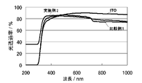
- the light transmittance of the electrode body of Example 2, the electrode body of Comparative Example 1, and the ITO electrode used as a substrate in the production process of these electrode bodies was measured with a visible ultraviolet spectrophotometer. The result is shown in FIG. Since the PEDOT layer in the electrode body of Example 2 is mainly composed of PEDOT particles of 100 nm or less, visible light easily passes through without scattering, and in the visible light region (360 to 830 nm), The light transmittance was almost the same as that of the electrode body.
- the thickness of the conductive polymer layer and the root mean square roughness (RMS) of the conductive polymer layer were measured with an atomic force microscope.
- the step at the interface between the conductive polymer layer forming part and the non-formed part (ITO electrode surface) on the ITO electrode was calculated as the film thickness of the polymer layer.
- the thickness of the polymer layer of the electrode body of Example 2 was 33 nm
- the thickness of the polymer layer of the electrode body of Comparative Example 1 was 41 nm.
- the RMS of the surface of the conductive polymer layer was calculated by observing the area of the surface 100 ⁇ 100 ⁇ m 2 at the center of the polymer layer.
- the polymer layer (RMS: 4.9 nm) of the electrode body of Example 2 has a slightly rougher surface than the polymer layer (RMS: 2.6 nm) of the electrode body of Comparative Example 1, but any polymer.
- the layer also had a smooth surface.
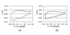
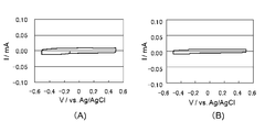
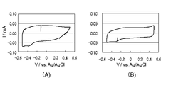
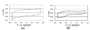
- the electrode bodies of Examples 1 and 2 and Comparative Examples 1, 2, 5, and 6 were taken out from the electrolyte solution, washed, and then subjected to thermal aging in air at 150 ° C. for 330 hours to obtain cyclic voltammograms again.
- Figures 3 to 8 show cyclic voltammograms before and after thermal aging. 3, 4, 5, 6, 7, and 8 are sequentially shown in Example 1 (dopant: bis (pentafluoroethanesulfonyl) imidate anion) and Example 2 (dopant: borodisalicylic acid). Anion), Comparative Example 1 (dopant: PSS anion), Comparative Example 2 (dopant: butylnaphthalene sulfonate anion), Comparative Example 5 (dopant: nitrate anion) and Comparative Example 6 (dopant: perchlorate anion) The cyclic voltammogram is shown.
- (A) is an initial cyclic voltammogram
- (B) is a cyclic voltammogram after thermal aging. It can be judged that the larger the electrochemical response in the cyclic voltammogram, the better the hole transport ability, and the smaller the change in the cyclic voltammogram before and after thermal aging, the better the heat resistance.
- the electrode body having the PEDOT: PSS layer of Comparative Example 1 has significantly smaller current response and poor electrochemical activity than the other electrode bodies. . Comparing the cyclic voltammograms before and after thermal aging, the electrode bodies of Examples 1 and 2 have a significantly smaller decrease in current response due to thermal experience than the electrode bodies of Comparative Examples 1, 2, 5, and 6. Recognize. Therefore, it was found that the electrode body of the present invention was excellent in hole transport ability and heat resistance.
- the electrode bodies of Comparative Examples 1 and 2 were compared with those of the electrode bodies of Comparative Examples 5 and 6, the decrease in the current response due to thermal experience was small, but the electrode bodies of Examples 1 and 2 were further It had excellent heat resistance.
- the electrode body of Example 1 obtained from a polymerization solution containing sodium bis (pentafluoroethanesulfonyl) imidate as a supporting electrolyte showed extremely excellent thermal stability.
- the electrode body for solar cells of the present invention is superior in the hole transport ability to an electrode body having a conventional PEDOT: PSS layer, and further contains an anion having a bulky sulfonic acid group or sulfonate group as a dopant. It turned out that it is excellent in heat resistance rather than the electrode body which has a PEDOT layer. From this result, it was judged that the electrode body for solar cells of this invention was suitable as a component in an organic thin film solar cell, ie, a component in which the anode and the hole extraction layer were integrated.
- FIG. 9 shows the cyclic voltammograms obtained from the cyclic electrodes of the ITO electrode used as a substrate in the production of these electrode bodies and the Pt electrode having a Pt layer having an area of 1 cm 2 on the glass plate by sputtering. Shown in comparison with voltammogram.
- a clear redox wave was not observed in the cyclic voltammogram of the ITO electrode. Two pairs of redox waves were clearly observed in the cyclic voltammograms of the electrode body of Example 1 and the Pt electrode.
- the negative potential side redox wave is a redox wave corresponding to I 3 ⁇ / I ⁇
- the positive potential side redox wave is a redox wave corresponding to I 2 / I 3 ⁇ .
- the reduction wave from I 3 ⁇ to I ⁇ observed around ⁇ 0.2 V with respect to the silver-silver chloride electrode is particularly important. This is because sufficient regeneration of I ⁇ is necessary.
- the electrode body of Example 1 converts I 3 ⁇ to I ⁇ as compared with the electrode body of Comparative Example 1 having a PEDOT: PSS layer that has been studied as an anode of a dye-sensitized solar cell. It was found that this was an electrode body that was excellent in reducing catalytic ability and could replace the Pt electrode as the anode of a dye-sensitized solar cell.
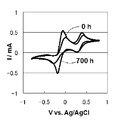
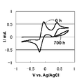
- the electrochemical response in the I ⁇ / I 3 ⁇ electrolytic solution was determined by cyclic voltammogram. Then, these electrode bodies were taken out from the electrolytic solution, washed, and then subjected to thermal aging in air at 130 ° C. for 700 hours to obtain a cyclic voltammogram again to evaluate heat resistance.
- the conditions for obtaining the cyclic voltammogram are the same as the conditions for obtaining the results of FIG.
- FIG. 10 to 12 show cyclic voltammograms before and after thermal aging.
- FIG. 10, FIG. 11 and FIG. 12 show, in order, Example 1 (dopant: bis (pentafluoroethanesulfonyl) imidate anion), Example 2 (dopant: borodisalicylate anion), and Comparative Example 2 (dopant: The cyclic voltammogram of the electrode body of butyl naphthalene sulfonate anion) is shown.
- the conductive polymer layer in the solar cell electrode body of the present invention is excellent in reduction catalytic ability to convert oxidized species (I 3 ⁇ ) to reduced species (I ⁇ ), and also has a bulky sulfonic acid group or sulfone. It turned out that it is excellent in heat resistance rather than the conductive polymer layer which contains the anion which has an acid base as a dopant. From this result, it was judged that the electrode body for solar cells of this invention was suitable as an anode in a dye-sensitized solar cell.
- Example 3 Distilled water (50 mL) was introduced into a glass container, and 0.140 g (concentration: 0.02 M) of EDOT was added to this solution to obtain a solution in which EDOT was phase-separated from water. To this solution, p-nitrophenol was added at a concentration of 0.02 M and ammonium borodisalicylate at a concentration of 0.08 M, respectively, and an ultrasonic wave having a frequency of 20 kHz and an output of 22.6 W / cm 2 was irradiated for 5 minutes. However, an emulsion dispersion in which EDOT was dispersed in water as oil droplets was obtained.
- An FTO electrode having an area of 1 cm 2 as a working electrode, a platinum mesh having an area of 4 cm 2 as a counter electrode, and a silver-silver chloride electrode as a reference electrode were introduced into the obtained polymerization solution, and 10 ⁇ A / cm 2
- the constant current electropolymerization was performed for 60 seconds under the following conditions.
- the working electrode after polymerization was washed with methanol and then dried at 150 ° C. for 30 minutes to obtain an electrode body (anode) in which a conductive polymer layer was formed on the FTO electrode.
- Titanium oxide paste (manufactured by JGC Catalysts & Chemicals Co., Ltd.) is applied to the surface of the ITO electrode by a bar coating method so that the film thickness is about 100 ⁇ m, pre-dried at 130 ° C. for 10 minutes, and further baked at 450 ° C. for 30 minutes. As a result, a titanium oxide porous layer was formed on the ITO electrode. Further, after immersing the titanium oxide porous layer in an ethanol solution containing dye N719 at a concentration of 0.2 mM for 3 hours and drying at room temperature, the dye N719 is attached to the titanium oxide porous layer, and dye sensitization is performed. A solar cell cathode was obtained.
- the obtained cathode and anode were laminated so that the titanium oxide porous layer and the conductive polymer layer were opposed to each other, and the electrolyte layer was impregnated to form an electrolyte layer.
- the electrolytic solution a solution prepared by dissolving 0.5 M lithium iodide, 0.05 M iodine, and 0.5 M 4-t-butylpyridine in acetonitrile was used. Finally, it was sealed with an epoxy resin to obtain a dye-sensitized solar cell.
- Comparative Example 7 The cathode obtained in Example 3 and an anode composed of a Pt electrode in which a Pt layer having an area of 1 cm 2 was formed on a steel substrate by sputtering were used so that the titanium oxide porous layer and the Pt layer face each other.
- the electrolyte layer was formed by laminating and impregnating the gap with an electrolytic solution.
- As the electrolytic solution a solution prepared by dissolving 0.5 M lithium iodide, 0.05 M iodine, and 0.5 M 4-t-butylpyridine in acetonitrile was used. Finally, it was sealed with an epoxy resin to obtain a dye-sensitized solar cell.
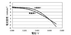
- Example 3 and Comparative Example 7 were evaluated for current-voltage characteristics under a solar simulator irradiation condition of 100 mW / cm 2 and AM1.5G. The measurement was performed at 20 ° C. while changing the voltage at a speed of 50 mV / s. FIG. 13 shows the results obtained. Table 1 summarizes the short-circuit current, open-circuit voltage, fill factor, and photoelectric conversion efficiency obtained from the measurement results of FIG. Although it did not reach the photoelectric conversion efficiency of the solar cell of Comparative Example 7 using the conventional Pt electrode as an anode, the photoelectric conversion efficiency exceeding 80% of the solar cell of Comparative Example 7 was also obtained in the solar cell of Example 3. .
- the electrode body for a solar cell of the present invention can be suitably used as a component of both an organic thin film solar cell and a dye-sensitized solar cell.
Landscapes
- Engineering & Computer Science (AREA)
- Power Engineering (AREA)
- Physics & Mathematics (AREA)
- Spectroscopy & Molecular Physics (AREA)
- Microelectronics & Electronic Packaging (AREA)
- Manufacturing & Machinery (AREA)
- Chemical & Material Sciences (AREA)
- Dispersion Chemistry (AREA)
- Electromagnetism (AREA)
- Hybrid Cells (AREA)
- Photovoltaic Devices (AREA)
- Electroluminescent Light Sources (AREA)
Abstract
Priority Applications (4)
| Application Number | Priority Date | Filing Date | Title |
|---|---|---|---|
| KR1020137025484A KR101904043B1 (ko) | 2011-03-31 | 2012-03-31 | 태양 전지용 전극체 및 그 제조 방법, 이 전극체를 구비한 태양 전지 |
| US14/008,137 US9184401B2 (en) | 2011-03-31 | 2012-03-31 | Electrode body for solar cell, method for producing the electrode body, and solar cell provided with the electrode body |
| EP12764251.0A EP2693505A4 (fr) | 2011-03-31 | 2012-03-31 | Corps d'électrode pour cellules solaires, procédé de fabrication de celui-ci, et cellule solaire équipée d'un corps électrode |
| CN201280016764.9A CN103477461B (zh) | 2011-03-31 | 2012-03-31 | 太阳能电池用电极体及其制造方法、具备该电极体的太阳能电池 |
Applications Claiming Priority (2)
| Application Number | Priority Date | Filing Date | Title |
|---|---|---|---|
| JP2011080676A JP5924514B2 (ja) | 2011-03-31 | 2011-03-31 | 太陽電池用電極体の製造方法 |
| JP2011-080676 | 2011-03-31 |
Publications (1)
| Publication Number | Publication Date |
|---|---|
| WO2012133859A1 true WO2012133859A1 (fr) | 2012-10-04 |
Family
ID=46931550
Family Applications (1)
| Application Number | Title | Priority Date | Filing Date |
|---|---|---|---|
| PCT/JP2012/058762 Ceased WO2012133859A1 (fr) | 2011-03-31 | 2012-03-31 | Corps d'électrode pour cellules solaires, procédé de fabrication de celui-ci, et cellule solaire équipée d'un corps électrode |
Country Status (6)
| Country | Link |
|---|---|
| US (1) | US9184401B2 (fr) |
| EP (1) | EP2693505A4 (fr) |
| JP (1) | JP5924514B2 (fr) |
| KR (1) | KR101904043B1 (fr) |
| CN (1) | CN103477461B (fr) |
| WO (1) | WO2012133859A1 (fr) |
Cited By (1)
| Publication number | Priority date | Publication date | Assignee | Title |
|---|---|---|---|---|
| WO2014003027A1 (fr) | 2012-06-26 | 2014-01-03 | 日本ケミコン株式会社 | Cellule solaire à colorant |
Families Citing this family (4)
| Publication number | Priority date | Publication date | Assignee | Title |
|---|---|---|---|---|
| CN103430262B (zh) * | 2011-03-01 | 2017-03-15 | 日本贵弥功株式会社 | 聚合液、由该聚合液得到的导电性聚合物膜及固体电解电容器 |
| KR101719143B1 (ko) * | 2015-11-30 | 2017-03-24 | 광주과학기술원 | 전도성 고분자가 코팅된 전극의 제조방법 |
| JP7596528B2 (ja) | 2021-05-24 | 2024-12-09 | パナソニックホールディングス株式会社 | 組成物およびそれを用いた電子デバイスの製造方法 |
| WO2022249647A1 (fr) | 2021-05-24 | 2022-12-01 | パナソニックホールディングス株式会社 | Dispositif électronique |
Citations (5)
| Publication number | Priority date | Publication date | Assignee | Title |
|---|---|---|---|---|
| JPH0350813A (ja) * | 1989-07-19 | 1991-03-05 | Nippon Chemicon Corp | 固体電解コンデンサの製造方法 |
| JP2000269087A (ja) | 1999-03-19 | 2000-09-29 | Matsushita Electric Ind Co Ltd | コンデンサの製造方法 |
| JP2006351289A (ja) * | 2005-06-14 | 2006-12-28 | Japan Carlit Co Ltd:The | 多孔性材料の製造方法、及び得られた多孔性材料を用いた製品 |
| JP2007119631A (ja) * | 2005-10-28 | 2007-05-17 | Achilles Corp | 導電性高分子微粒子の製造方法及びその導電性高分子微粒子 |
| WO2011108254A1 (fr) * | 2010-03-01 | 2011-09-09 | 国立大学法人東京工業大学 | Liquide polymérisant, procédé de fabrication de ce liquide polymériasant, et film ainsi qu'électrode transparents obtenus à partir de ce liquide polymérisant |
Family Cites Families (7)
| Publication number | Priority date | Publication date | Assignee | Title |
|---|---|---|---|---|
| JP2000001884A (ja) * | 1998-06-17 | 2000-01-07 | Toto Ltd | 水路分岐部材、止水部材および吐水装置 |
| US7732229B2 (en) * | 2004-09-18 | 2010-06-08 | Nanosolar, Inc. | Formation of solar cells with conductive barrier layers and foil substrates |
| US7569158B2 (en) * | 2004-10-13 | 2009-08-04 | Air Products And Chemicals, Inc. | Aqueous dispersions of polythienothiophenes with fluorinated ion exchange polymers as dopants |
| JP2007128757A (ja) * | 2005-11-04 | 2007-05-24 | Erekuseru Kk | 色素増感太陽電池 |
| JP5085117B2 (ja) * | 2006-05-23 | 2012-11-28 | 東海ゴム工業株式会社 | 導電性組成物およびそれを用いた導電性部材 |
| JP5560996B2 (ja) * | 2009-07-31 | 2014-07-30 | 大日本印刷株式会社 | 正孔注入輸送層用デバイス材料、正孔注入輸送層形成用インク、正孔注入輸送層を有するデバイス、及びその製造方法 |
| JP5885084B2 (ja) * | 2011-03-01 | 2016-03-15 | 日本ケミコン株式会社 | 重合液、この重合液を用いた導電性ポリマーフィルム、ポリマー電極及び固体電解コンデンサの製造方法 |
-
2011
- 2011-03-31 JP JP2011080676A patent/JP5924514B2/ja not_active Expired - Fee Related
-
2012
- 2012-03-31 CN CN201280016764.9A patent/CN103477461B/zh not_active Expired - Fee Related
- 2012-03-31 WO PCT/JP2012/058762 patent/WO2012133859A1/fr not_active Ceased
- 2012-03-31 KR KR1020137025484A patent/KR101904043B1/ko not_active Expired - Fee Related
- 2012-03-31 EP EP12764251.0A patent/EP2693505A4/fr not_active Withdrawn
- 2012-03-31 US US14/008,137 patent/US9184401B2/en not_active Expired - Fee Related
Patent Citations (5)
| Publication number | Priority date | Publication date | Assignee | Title |
|---|---|---|---|---|
| JPH0350813A (ja) * | 1989-07-19 | 1991-03-05 | Nippon Chemicon Corp | 固体電解コンデンサの製造方法 |
| JP2000269087A (ja) | 1999-03-19 | 2000-09-29 | Matsushita Electric Ind Co Ltd | コンデンサの製造方法 |
| JP2006351289A (ja) * | 2005-06-14 | 2006-12-28 | Japan Carlit Co Ltd:The | 多孔性材料の製造方法、及び得られた多孔性材料を用いた製品 |
| JP2007119631A (ja) * | 2005-10-28 | 2007-05-17 | Achilles Corp | 導電性高分子微粒子の製造方法及びその導電性高分子微粒子 |
| WO2011108254A1 (fr) * | 2010-03-01 | 2011-09-09 | 国立大学法人東京工業大学 | Liquide polymérisant, procédé de fabrication de ce liquide polymériasant, et film ainsi qu'électrode transparents obtenus à partir de ce liquide polymérisant |
Non-Patent Citations (4)
| Title |
|---|
| ELECTROCHEMISTRY, vol. 71, no. 11, 2003, pages 944 - 946 |
| J. AM. CHEM. SOC., vol. 127, no. 38, 2005, pages 13160 - 13161 |
| See also references of EP2693505A4 |
| SOLAR ENERGY MATERIALS & SOLAR CELLS, vol. 94, 2010, pages 623 - 628 |
Cited By (1)
| Publication number | Priority date | Publication date | Assignee | Title |
|---|---|---|---|---|
| WO2014003027A1 (fr) | 2012-06-26 | 2014-01-03 | 日本ケミコン株式会社 | Cellule solaire à colorant |
Also Published As
| Publication number | Publication date |
|---|---|
| CN103477461B (zh) | 2016-08-10 |
| JP5924514B2 (ja) | 2016-05-25 |
| EP2693505A1 (fr) | 2014-02-05 |
| KR20140014196A (ko) | 2014-02-05 |
| CN103477461A (zh) | 2013-12-25 |
| US20140014168A1 (en) | 2014-01-16 |
| EP2693505A4 (fr) | 2014-09-03 |
| US9184401B2 (en) | 2015-11-10 |
| KR101904043B1 (ko) | 2018-10-04 |
| JP2012216673A (ja) | 2012-11-08 |
Similar Documents
| Publication | Publication Date | Title |
|---|---|---|
| JP6070542B2 (ja) | 太陽電池用電極体及びその製造方法、この電極体を備えた太陽電池 | |
| US20060070651A1 (en) | Highly efficient counter electrode for dye-sensitized solar cell and method of producing the same | |
| US20110000527A1 (en) | Method for producing electroconductive polymer electrode, and dye-sensitized solar cell equipped with the same | |
| Senadeera et al. | Photosensitization of nanocrystalline TiO2 films by a polymer with two carboxylic groups, poly (3-thiophenemalonic acid) | |
| JP5924514B2 (ja) | 太陽電池用電極体の製造方法 | |
| KR101726127B1 (ko) | 블록 공중합체를 이용한 염료감응 태양전지용 상대전극 및 이를 포함하는 염료감응 태양전지 | |
| Kurokawa et al. | Controlling the electrocatalytic activities of conducting polymer thin films toward suitability as cost-effective counter electrodes of dye-sensitized solar cells | |
| JP6287845B2 (ja) | 有機薄膜太陽電池 | |
| JP6218046B2 (ja) | 色素増感太陽電池 | |
| JP6024359B2 (ja) | 色素増感太陽電池 | |
| JP6519475B2 (ja) | 色素増感太陽電池 | |
| HK40056273B (zh) | 染料敏化的光伏电池 | |
| JP2014005410A (ja) | 重合液、この重合液から得られた導電性ポリマーフィルム及び電極体 | |
| KR20100130529A (ko) | 올리고머를 포함하는 고체 고분자 전해질을 적용한 염료감응 태양전지 및 이의 제조방법 |
Legal Events
| Date | Code | Title | Description |
|---|---|---|---|
| 121 | Ep: the epo has been informed by wipo that ep was designated in this application |
Ref document number: 12764251 Country of ref document: EP Kind code of ref document: A1 |
|
| ENP | Entry into the national phase |
Ref document number: 20137025484 Country of ref document: KR Kind code of ref document: A |
|
| WWE | Wipo information: entry into national phase |
Ref document number: 2012764251 Country of ref document: EP |
|
| WWE | Wipo information: entry into national phase |
Ref document number: 14008137 Country of ref document: US |
|
| NENP | Non-entry into the national phase |
Ref country code: DE |