WO2012134155A2 - 이동통신 시스템에서 랜덤 액세스 방법 및 장치 - Google Patents
이동통신 시스템에서 랜덤 액세스 방법 및 장치 Download PDFInfo
- Publication number
- WO2012134155A2 WO2012134155A2 PCT/KR2012/002252 KR2012002252W WO2012134155A2 WO 2012134155 A2 WO2012134155 A2 WO 2012134155A2 KR 2012002252 W KR2012002252 W KR 2012002252W WO 2012134155 A2 WO2012134155 A2 WO 2012134155A2
- Authority
- WO
- WIPO (PCT)
- Prior art keywords
- random access
- terminal
- terminal group
- group
- base station
- Prior art date
- Legal status (The legal status is an assumption and is not a legal conclusion. Google has not performed a legal analysis and makes no representation as to the accuracy of the status listed.)
- Ceased
Links
Images


Classifications
-
- H—ELECTRICITY
- H04—ELECTRIC COMMUNICATION TECHNIQUE
- H04W—WIRELESS COMMUNICATION NETWORKS
- H04W28/00—Network traffic management; Network resource management
- H04W28/16—Central resource management; Negotiation of resources or communication parameters, e.g. negotiating bandwidth or QoS [Quality of Service]
- H04W28/26—Resource reservation
-
- H—ELECTRICITY
- H04—ELECTRIC COMMUNICATION TECHNIQUE
- H04L—TRANSMISSION OF DIGITAL INFORMATION, e.g. TELEGRAPHIC COMMUNICATION
- H04L5/00—Arrangements affording multiple use of the transmission path
- H04L5/003—Arrangements for allocating sub-channels of the transmission path
- H04L5/0053—Allocation of signalling, i.e. of overhead other than pilot signals
-
- H—ELECTRICITY
- H04—ELECTRIC COMMUNICATION TECHNIQUE
- H04W—WIRELESS COMMUNICATION NETWORKS
- H04W74/00—Wireless channel access
- H04W74/08—Non-scheduled access, e.g. ALOHA
-
- H—ELECTRICITY
- H04—ELECTRIC COMMUNICATION TECHNIQUE
- H04W—WIRELESS COMMUNICATION NETWORKS
- H04W74/00—Wireless channel access
- H04W74/08—Non-scheduled access, e.g. ALOHA
- H04W74/0833—Random access procedures, e.g. with 4-step access
-
- H—ELECTRICITY
- H04—ELECTRIC COMMUNICATION TECHNIQUE
- H04W—WIRELESS COMMUNICATION NETWORKS
- H04W74/00—Wireless channel access
- H04W74/08—Non-scheduled access, e.g. ALOHA
- H04W74/0866—Non-scheduled access, e.g. ALOHA using a dedicated channel for access
- H04W74/0875—Non-scheduled access, e.g. ALOHA using a dedicated channel for access with assigned priorities based access
-
- H—ELECTRICITY
- H04—ELECTRIC COMMUNICATION TECHNIQUE
- H04W—WIRELESS COMMUNICATION NETWORKS
- H04W74/00—Wireless channel access
- H04W74/002—Transmission of channel access control information
- H04W74/006—Transmission of channel access control information in the downlink, i.e. towards the terminal
-
- H—ELECTRICITY
- H04—ELECTRIC COMMUNICATION TECHNIQUE
- H04W—WIRELESS COMMUNICATION NETWORKS
- H04W74/00—Wireless channel access
- H04W74/08—Non-scheduled access, e.g. ALOHA
- H04W74/0833—Random access procedures, e.g. with 4-step access
- H04W74/0838—Random access procedures, e.g. with 4-step access using contention-free random access [CFRA]
Definitions
- the following description is about a method and apparatus for performing a random access procedure in a mobile communication system.
- Wireless communication systems are widely deployed to provide various kinds of communication services such as voice and data.
- a wireless communication system is a multiple access system capable of supporting communication with multiple users by sharing available system resources (bandwidth, transmission power, etc.).
- multiple access systems include code division multiple access (CDMA) systems, frequency division multiple access (FDMA) systems, time division multiple access (TDMA) systems, orthogonal frequency division multiple access (OFDMA) systems, and single carrier frequency (SC-FDMA).
- CDMA code division multiple access
- FDMA frequency division multiple access
- TDMA time division multiple access
- OFDMA orthogonal frequency division multiple access
- SC-FDMA single carrier frequency division multiple access
- MCD division multiple access
- MCDMA multi-carrier frequency division multiple access
- MC-FDMA multi-carrier frequency division multiple access
- the present invention relates to a random access procedure for a large number of terminals temporarily accessing a base station area.
- a method for a terminal to perform random access in a mobile communication system comprising: transmitting a random access preamble using a resource determined according to a random access setting for the terminal; And receiving a random access response including uplink grant information from a base station as a response to the preamble transmission, wherein the random access setting comprises: a first random access setting or a second terminal group for a first terminal group; The UE is determined by the corresponding group among the second random access configuration for the resource, the resource reserved for the second terminal group according to the second random access configuration, the random access preamble transmission or uplink data transmission It is used for, the method of performing a random access of the terminal.
- a method of performing a random access by a base station in a mobile communication system comprising: receiving a random access preamble transmitted on a resource determined according to a random access setting from a terminal; And transmitting a random access response including uplink grant information as a response to the preamble transmission, wherein the random access setting comprises: a first random access setting for a first terminal group or a second terminal group; Among the second random access configuration, the terminal is determined by the corresponding group, and the resource reserved for the second terminal group according to the second random access configuration is used for the random access preamble transmission or the uplink data transmission.
- the random access method of the base station comprising: receiving a random access preamble transmitted on a resource determined according to a random access setting from a terminal; And transmitting a random access response including uplink grant information as a response to the preamble transmission, wherein the random access setting comprises: a first random access setting for a first terminal group or a second terminal group; Among the second random access configuration, the terminal is determined by
- a third technical aspect of the present invention is a terminal for performing random access in a mobile communication system, comprising: a transmission module; And a processor, wherein the processor is configured to control to transmit a random access preamble using a resource determined according to a random access setting for the terminal, wherein the random access setting is configured to include a first random access setting for a first terminal group or Among the second random access configuration for the second terminal group, the terminal is determined by the corresponding group, and the resource reserved for the second terminal group according to the second random access configuration is the random access preamble transmission or uplink A terminal for performing random access, which is used for data transmission.
- a fourth technical aspect of the present invention is a base station for performing random access in a mobile communication system, comprising: a transmission module; And a processor, wherein the processor is configured to control to transmit a random access response including uplink grant information as a response to a random access preamble transmitted from a terminal to a resource determined according to a random access setting, and the random access setting Is determined by the corresponding group among the first random access setting for the first terminal group or the second random access setting for the second terminal group, and the second terminal group is determined according to the second random access setting.
- the reserved resource is a base station that performs random access, which is used for the random access preamble transmission or the uplink data transmission.
- the first to fourth technical aspects of the present invention may include all of the following.
- the resource reserved for the second terminal group according to the second random access setting is the first terminal group or the second terminal before or after the start of the random access procedure of the terminal included in the second terminal group. It may be used for the uplink data transmission of the terminal included in the terminal group.
- the second terminal group may include more than a preset number of terminals simultaneously accessing the base station, and the first terminal group may include terminals that do not belong to the second terminal group in the base station area.
- the second terminal group may include terminals that temporarily hand over to the base station, and the first terminal group may include terminals that do not belong to the second terminal group in the base station region.
- Resources reserved for the first terminal group according to the first random access setting may be distinguished in one or more areas of resources and time or frequency reserved for the second terminal group according to the second random access setting. have.
- the random access response is transmitted on a physical downlink common channel (PDSCH) indicated by a physical downlink control channel (PDCCH), wherein the first terminal group and the second terminal group correspond to different time-frequency resources.
- PDSCH can be used.
- PUSCH physical uplink control channel
- the terminals included in the second terminal group are included in the mobile relay node immediately before attempting to access the base station. If the terminals included in the second terminal group were included in the mobile relay node immediately before attempting to access the base station, the terminals included in the second terminal group are the multicast handover commands of the mobile relay node. According to the random access procedure may be initiated.
- the multicast handover command may include an index of terminals included in the second terminal group, and the index may correspond to a resource determined according to the second random access configuration.
- Terminals included in the second terminal group receive a multicast scheduling signal from the mobile relay node, the multicast scheduling signal includes an index of terminals included in the second terminal group, and the index is the terminal. It may correspond to an uplink resource or a downlink resource for each of them.
- the multicast handover message may be valid only for a preset time.
- a large number of terminals temporarily accessing the base station area can perform a random access procedure smoothly.
- 1 is a view for explaining the structure of an LTE system.
- FIG. 2 is a diagram illustrating a structure of a radio frame used in an LTE system.
- 3 is a diagram illustrating a resource grid in a downlink slot.
- FIG. 4 is a diagram illustrating a structure of an uplink subframe.
- 5 is a diagram illustrating a structure of a downlink subframe.
- FIG. 6 is a diagram illustrating a wireless communication system including a relay.
- FIG. 7 is a diagram illustrating an example of performing backhaul transmission using an MBSFN subframe.
- FIG. 9 is a diagram illustrating an example in which a large number of terminals attempt simultaneous access to a base station area.
- FIG. 10 is a view for explaining a terminal group according to an embodiment of the present invention.
- FIG. 11 illustrates a time-frequency resource region for each UE group according to an embodiment of the present invention.
- FIG. 12 is a diagram for explaining division of a terminal group according to an embodiment of the present invention.
- FIG. 13 illustrates a broadcast / multicast handover message according to an embodiment of the present invention.
- FIG. 14 illustrates a broadcast / multicast scheduling signal according to an embodiment of the present invention.
- 15 is a flowchart illustrating a handover process of a terminal belonging to a mobile relay node according to an embodiment of the present invention.
- 16 is a diagram showing the configuration of a base station apparatus and a terminal apparatus according to an embodiment of the present invention.
- a terminal collectively refers to a mobile or fixed user terminal device such as a user equipment (UE), a mobile station (MS), and the like.
- the base station collectively refers to any node of the network side that communicates with the terminal, such as Node B, eNode B, Base Station.
- an E-UMTS is located at an end of a user equipment (UE) 120, a base station (eNode B, eNB) 110a and 110b, and a network (E-UTRAN) to be connected to an external network.
- Access Gateway (AG) is included.
- the base station may transmit multiple data streams simultaneously for broadcast service, multicast service and / or unicast service.
- the cell is set to one of the bandwidths of 1.4, 3, 5, 10, 15, 20Mhz, etc. to provide downlink or uplink transmission service to multiple terminals. Different cells may be configured to provide different bandwidths.
- the base station controls data transmission and reception for a plurality of terminals.
- the base station For downlink (DL) data, the base station transmits downlink scheduling information to inform the corresponding UE of time / frequency domain, encoding, data size, and HARQ (Hybrid Automatic Repeat and reQuest) related information. In addition, the base station transmits uplink scheduling information to the terminal for uplink (UL) data, and informs the time / frequency domain, encoding, data size, HARQ related information, etc. that the terminal can use.
- An interface for transmitting user traffic or control traffic may be used between base stations.
- the core network Core Network, CN
- the AG manages the mobility of the UE in units of a tracking area (TA) composed of a plurality of cells.
- TA tracking area
- FIG. 2 (a) is a diagram illustrating a structure of a radio frame used in a 3GPP LTE system.
- One radio frame includes 10 subframes, and one subframe includes two slots in the time domain.
- the time for transmitting one subframe is defined as a transmission time interval (TTI).
- TTI transmission time interval
- one subframe may have a length of 1 ms, and one slot may have a length of 0.5 ms.
- One slot may include a plurality of OFDM symbols in the time domain. Since the 3GPP LTE system uses the OFDMA scheme in downlink, the OFDM symbol represents one symbol length.
- One symbol may be referred to as an SC-FDMA symbol or a symbol length in uplink.
- a resource block (RB) is a resource allocation unit and includes a plurality of consecutive subcarriers in one slot.
- the structure of such a radio frame is merely exemplary. Accordingly, the number of subframes included in one radio frame, the number of slots included in one subframe, or the number of OFDM symbols included in one slot may be changed in various ways.
- Type 2 (b) illustrates the structure of a type 2 radio frame.
- Type 2 radio frames consist of two half frames. Each half frame consists of five subframes, a Downlink Pilot Time Slot (DwPTS), a Guard Period (GP), and an Uplink Pilot Time Slot (UpPTS), of which one subframe consists of two slots.
- DwPTS is used for initial cell search, synchronization or channel estimation at the terminal.
- UpPTS is used for channel estimation at the base station and synchronization of uplink transmission of the terminal.
- the guard period is a period for removing interference generated in the uplink due to the multipath delay of the downlink signal between the uplink and the downlink.
- the structure of the radio frame is merely an example, and the number of subframes included in the radio frame or the number of slots included in the subframe and the number of symbols included in the slot may be variously changed.
- One downlink slot includes seven OFDM symbols in the time domain and one resource block (RB) is shown to include 12 subcarriers in the frequency domain, but the present invention is not limited thereto.
- one slot includes 7 OFDM symbols in the case of a general cyclic prefix (CP), but one slot may include 6 OFDM symbols in the case of an extended-CP (CP).
- Each element on the resource grid is called a resource element (RE).
- One resource block includes 12 x 7 resource elements.
- the number of NDLs of resource blocks included in a downlink slot depends on a downlink transmission bandwidth.
- the structure of the uplink slot may be the same as the structure of the downlink slot.
- the uplink subframe may be divided into a control region and a data region in the frequency domain.
- a physical uplink control channel (PUCCH) including uplink control information is allocated to the control region.
- a physical uplink shared channel (PUSCH) including user data is allocated.
- PUCCH physical uplink control channel
- PUSCH physical uplink shared channel
- one UE does not simultaneously transmit a PUCCH and a PUSCH.
- PUCCH for one UE is allocated to an RB pair in a subframe. Resource blocks belonging to a resource block pair occupy different subcarriers for two slots. This is called a resource block pair allocated to the PUCCH is frequency-hopped at the slot boundary.
- FIG. 5 is a diagram illustrating a structure of a downlink subframe.
- Up to four OFDM symbols at the front of the first slot in one subframe correspond to a control region to which a control channel is allocated.
- the remaining OFDM symbols correspond to data regions to which a physical downlink shared channel (PDSCH) is allocated.
- Downlink control channels used in the 3GPP LTE system include, for example, a physical control format offset channel (PCFICH), a physical downlink control channel (PDCCH), and a physical HARQ offset channel. (Physical Hybrid automatic repeat request Indicator Channel, PHICH).
- the PCFICH is transmitted in the first OFDM symbol of a subframe and includes information on the number of OFDM symbols used for control channel transmission in the subframe.
- the PHICH includes a HARQ ACK / NACK signal as a response of uplink transmission.
- the PDCCH includes uplink or downlink scheduling information and power control information.
- the relay facilitates the service by extending the service area of the base station or installing in a shaded area.
- a wireless communication system includes a base station, a relay, and a terminal.
- the terminal communicates with the base station or the relay.
- a terminal that communicates with a base station is referred to as a macro UE, and a terminal that communicates with a relay is referred to as a relay UE.
- the communication link between the base station and the macro terminal is referred to as a macro access link, and the communication link between the relay and the relay terminal is referred to as a relay access link.
- the communication link between the base station and the relay is referred to as a backhaul link.
- Relays may be divided into L1 (layer 1) relays, L2 (layer 2) relays, and L3 (layer 3) relays according to how much they perform in multi hop transmission.
- the relay is an in-band connection in which the network-relay link and the network-terminal link share the same frequency band in the donor cell according to the network link, and the network-relay link in the donor cell.
- network-terminal links may be divided into out-band connections using different frequency bands.
- the terminal may be divided into a transparent relay whose terminal does not know whether it is communicating through a relay and a non-transparent relay which knows whether the terminal communicates through the relay. have.
- relays are fixed relays that can be used to increase shadow area or cell coverage, nomadic relays that can be temporarily installed or moved randomly when users suddenly increase, or public transportation such as buses or trains. It can be divided into a mobile relay that can be mounted on.
- the base station-relay link (ie, backhaul link) operates in the same frequency band as the relay-end link (ie, relay access link).
- the relay transmitter and receiver cause interference with each other, so that the relay can simultaneously transmit and receive.
- the backhaul link and the relay access link are partitioned in a TDM manner.
- LTE-A configures a backhaul link in an MBSFN subframe to support measurement operation of a legacy LTE terminal existing in a relay zone (fake MBSFN method). If any subframe is signaled to the MBSFN subframe, the terminal receives only the control region (ctrl) of the corresponding subframe, and thus the relay may configure the backhaul link using the data region of the corresponding subframe.
- the UE may perform a random access process in the following cases.
- uplink data When uplink data is not synchronized, or when uplink data is generated in a situation where a designated radio resource used for requesting a radio resource is not allocated.
- FIG. 8 is a diagram illustrating an operation process of a terminal and a base station in a contention-based random access process.
- a UE randomly selects one random access preamble from a set of random access preambles indicated by system information or a handover command, and transmits the random access preamble (PRACH).
- the resource may be selected and transmitted (S801).
- the terminal After transmitting the random access preamble as in step S801, the terminal attempts to receive its random access response within the random access response receiving window indicated by the system information or the handover command (S802).
- the random access response information may be transmitted in the form of a MAC PDU, and the MAC PDU may be transmitted through a physical downlink shared channel (PDSCH).
- PDSCH physical downlink shared channel
- the UE monitors a physical downlink control channel (PDCCH). That is, the PDCCH preferably includes information of a terminal that should receive the PDSCH, frequency and time information of radio resources of the PDSCH, a transmission format of the PDSCH, and the like.
- the UE After the UE succeeds in receiving the PDCCH transmitted to the UE, it can properly receive the random access response transmitted to the PDSCH according to the information of the PDCCH.
- the random access response includes a random access preamble identifier (ID), for example, a random access preamble identifier (RAPID), an uplink grant indicating an uplink radio resource, a UL grant, and a temporary C-RNTI.
- ID random access preamble identifier
- RAPID random access preamble identifier
- TACs timing synchronization commands
- the reason why the random access (or random access) preamble discriminator is needed in the random access response is that the UL grant may be included because one random access response may include random access response information for one or more terminals. This is because it is necessary to inform which UE the temporary cell identifier and the TAC are valid. In this step, it is assumed that the UE selects a random access preamble identifier that matches the random access preamble selected by the UE in step S802. Through this, the UE may receive an UL grant, a temporary C-RNTI, a timing synchronization command (TAC), and the like.
- TAC timing synchronization command
- the terminal When the terminal receives a valid random access response to the terminal, it processes each of the information included in the random access response. That is, the terminal applies the TAC and stores the temporary cell identifier.
- the data to be transmitted may be stored in the message 3 buffer in response to receiving a valid random access response.
- the terminal transmits data (ie, a third message) to the base station by using the received UL grant (S803).
- the third message should include the identifier of the terminal.
- the base station cannot determine which terminals perform the random access process, because the terminal needs to be identified for future collision resolution.
- Two methods have been discussed as a method of including the identifier of the terminal.
- the first method if the UE already has a valid cell identifier assigned to the cell before the random access procedure, the UE transmits its cell identifier through an uplink transmission signal corresponding to the UL grant.
- the terminal transmits its own unique identifier (eg, S-TMSI or random ID). In general, the unique identifier is longer than the cell identifier.
- the UE transmits data corresponding to the UL grant it starts a timer for contention resolution (hereinafter referred to as "CR timer").
- the UE After the UE transmits data including its identifier through the UL grant included in the random access response, it waits for an instruction of the base station to resolve the collision. That is, an attempt is made to receive a PDCCH in order to receive a specific message (S804). Two methods have been discussed in the method of receiving the PDCCH. As mentioned above, when the third message transmitted in response to the UL grant is transmitted using a cell identifier of its own, it attempts to receive the PDCCH using its cell identifier, and the identifier is a unique identifier. In this case, it may attempt to receive the PDCCH using the temporary cell identifier included in the random access response.
- the terminal determines that the random access procedure has been normally performed, and terminates the random access procedure.
- the terminal determines that the random access procedure has been normally performed, and terminates the random access procedure.
- the terminal determines that the random access procedure has been normally performed, and ends the random access procedure.
- the operation in the non-competition-based random access process ends the random access procedure only by transmitting the first message and transmitting the second message.
- the terminal before the terminal transmits the random access preamble to the base station as the first message, the terminal is allocated a random access preamble from the base station, and transmits the allocated random access preamble to the base station as the first message, and the random access response from the base station.
- the random access procedure is terminated by receiving.
- the random access process described above may reduce efficiency when a plurality of terminals attempt to establish a connection or release a connection at the same time.
- a plurality of terminals may access a specific base station through a bus, a train or an aircraft.
- the terminals on the bus, train or aircraft are used for initial connection (for example, when the terminals are turned off at the same time, etc.) without handover to the base station or without a connection with the base station.
- the access to the base station may be delayed or even unable to connect due to initiation of the random access procedure.
- methods for smoothly performing a random access procedure in this case are disclosed.
- UEs in a specific base station area are set to group 1, and terminals which start a random access process to a specific base station at the same time by the bus, train or aircraft are set to group 2.
- the terminals included in the group 1 and the terminals included in the group 2 may be configured to use different resources. That is, resources for transmitting the first message of the random access procedure may be set to different regions in the time or frequency domain (see FIG. 11 (a)). Similarly, time frequency resources for the uplink common channel (PUSCH) and the downlink common channel (PDSCH) may also be set to different regions in the time or frequency domain for group 1 and group 2 (see FIG. 11 (b)). ).
- PUSCH uplink common channel
- PDSCH downlink common channel
- the case of the first message transmission in the random access process will be described as an example.
- transmission of the first message including the random access preamble is transmitted through a PRACH resource indicated by a random access configuration.
- the PRACH resource is generally composed of six resource blocks (RBs), and the subcarrier spacing may be different from that of the PUSCH resource.
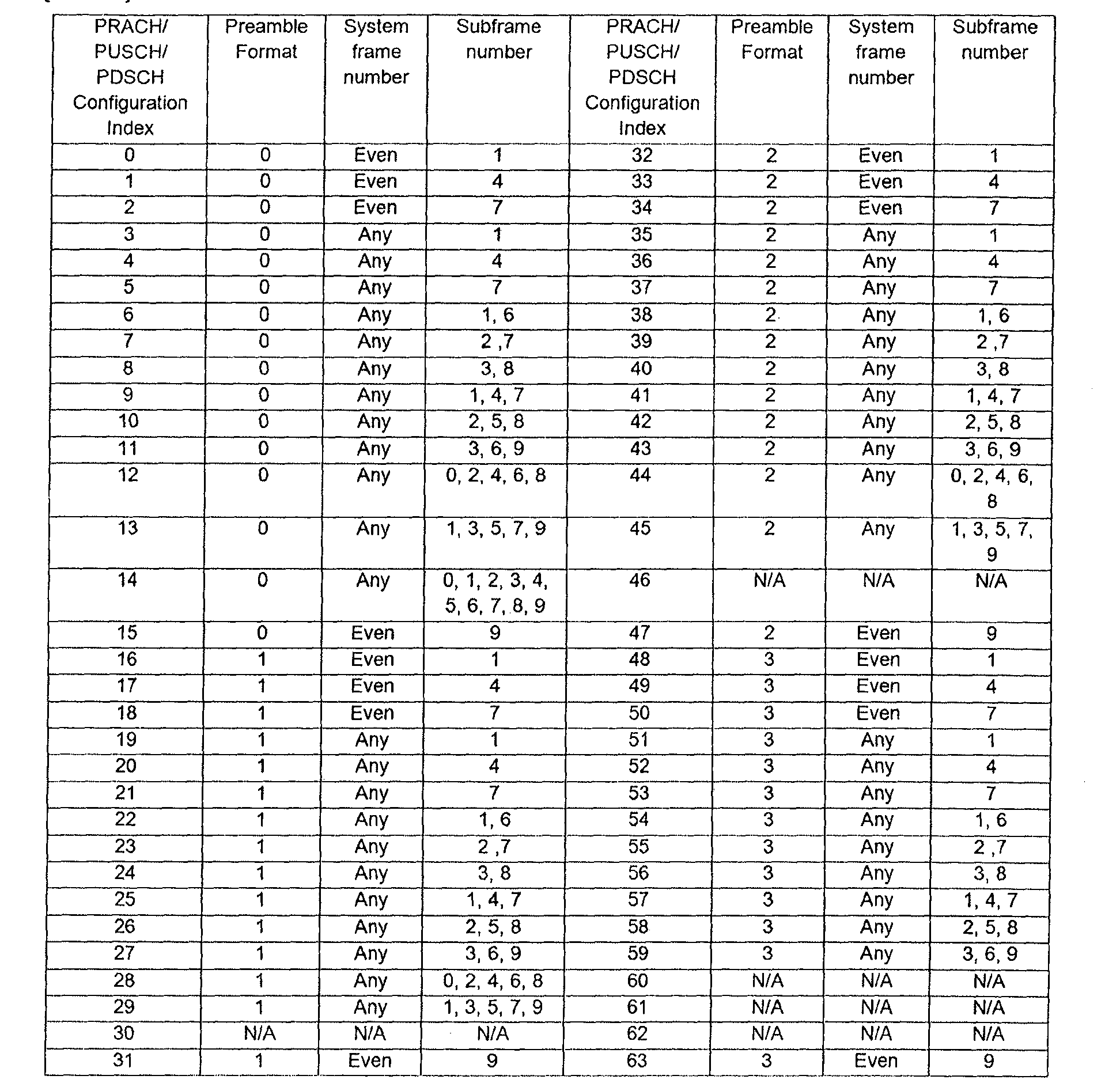
- the PRACH resource is reserved for the first message transmission in the random access procedure and is a resource that is not used for uplink data transmission in most cases. Random access configuration that can be applied to the present invention, in the case of FDD is shown in Table 1 below.
- a PRACH configuration index 0 means that a random access preamble is transmitted through a first subframe in a frame having an even number of system frames, which is available in preamble format 0.
- the PRACH configuration indexes listed in Table 1 may be set to use different indexes in Group 1 and Group 2.
- the PRACH configuration indexes of Table 1 may be divided into two sets, and then allocated to each group. For example, PRACH configuration indexes 0-2, 15-18, 31-34, 47-50, and 63 with even system frame numbers are allocated for group 1 and the remaining PRACH configuration indexes for group 2. can do.
- the set of PRACH configuration indexes allocated to group 2 may not be used when the terminals belonging to group 2 do not exist in the base station area. In this case, the PRACH configuration indexes of Table 1 may be appropriately modified and used.
- the PRACH configuration indexes of Table 1 may be assigned to Group 1, and the newly added PRACH configuration indexes may be assigned to Group 2.
- the newly added PRACH configuration indexes are preferably configured such that resource regions used by the terminals of group 1 and group 2 can be distinguished.
- group 1 may be configured to transmit a preamble only in even-numbered subframes (or system frame numbers), and group 2 may attempt to connect only in odd-numbered subframes (or system frames).
- the PRACH configuration indexes can be divided into groups 1 and 2, wherein the time-frequency resource designated by the PRACH configuration index for group 2 is determined before the start of the random access procedure of the UEs included in the group 2, or After the termination is preferably configured to be used as a PUSCH resource.
- the PRACH resources indicated by the PRACH configuration index are not usually scheduled for uplink data transmission because transmission of the random access preamble may occur randomly.
- the resource for group 2 i.e., the resource indicated by the PRACH configuration indexes for group 2 is characteristic of group 2 (e.g., group 2 is a set of terminals in a particular train, the train being a base station). This is because it may be inefficient to keep it as a PRACH resource continuously.
- the resource indicated by the PRACH configuration for the group 1 and the resource indicated by the PRACH configuration for the group 2 are as shown in Fig. 11 (a). It may be set to different areas on the frequency axis or the time axis. Even in this case, the resource indicated by the PRACH configuration for the group 2 may be configured to be used as a PUSCH resource when the terminals included in the group 2 do not exist in the base station area.
- the transmission of the random access preamble is multiplexed on the frequency axis, there is a disadvantage in that a processing peak of the base station may increase.
- the base station may determine that the terminals correspond to group 2.
- the threshold number is set too low, the resources for group 2 may be allocated to the terminals belonging to the group 1, so that the threshold number is set in consideration of the number of terminals transmitting the random access preamble at the same time in a normal situation. It is necessary to set appropriately.
- the appointment may include specific indication information, preamble sequence, transmission to a specific resource region, and the like.
- preamble sequence 64 random access preambles selected randomly by the UE may be divided into preamble set 1, preamble set 2, and preambles for non-competitive access. In general, the UE randomly selects and transmits one of the 64 random access preambles.
- the UE belonging to group 1 may transmit a preamble belonging to preamble set 1 only, and the UE belonging to group 2 may promise to transmit only a preamble belonging to preamble set 2.
- a scheme of adding preamble set 3 for group 2 to the existing 64 preambles may be used.
- the promised preamble is transmitted through an emergency access attempt button (or a user interface) in the terminal device. Can be implemented.
- the bus, train, aircraft, etc. to which the terminal belongs may inform the base station that the terminals belonging to group 2.
- the terminal user when the terminal user is boarded in the means of transportation, a process of registering the terminal with the authentication registration device provided in the means of transportation is required.
- Signal transmission for registration in the authentication registration device may be used Bluetooth, RF (Radio Frequency) transmission, LTE / LTE-A and the like.
- the mobile relay node 1401 when the mobile relay node 1401 is installed in a transportation means such as a bus, a train, an aircraft, as shown in FIG. 12 (b), the mobile relay node 1401 transmits to the base station 1411 to the base station 1411.
- Information such as the number of connected terminals and the estimated time of arrival may be notified through a backhaul or the like.
- the information notified to the base station 1411 from the mobile relay node 1401 may include information necessary for the terminals to be handed over to the base station to access the base station without collision, in addition to the number of terminals.
- the base station may know which group the UE belongs to in Group 1 and Group 2, and the UEs belonging to Group 2 may receive random access preamble, uplink data, etc. through separately allocated resources. Can be sent. For example, a specific UE belonging to the group 2 is informed of the PRACH configuration index for the group 2 in the handover command, and the terminal may transmit the random access preamble using the time-frequency resource indicated by the corresponding PRACH configuration index.
- FIG. 14 (b) transmitting a handover message to each of the terminals included in the vehicle in which the mobile relay node is installed has a large signal overhead. Therefore, hereinafter, a method of transmitting a handover message using one medium access control (MAC) broadcast / multicast signal is disclosed.
- MAC medium access control
- a specific terminal 1 belonging to group 2 receives a multicast handover message 1301 from a mobile relay node, and then time-frequency resources indicated by PRACH configuration index 1 associated with its identifier UE1.
- the random access preamble can be transmitted.
- the PRACH configuration index associated with the multicast handover message 1301 may be a logical index, and in this case, may correspond to the PRACH configuration index for group 2 described above. That is, it may correspond to the PRACH configuration index (0-2, 15-18, 31-34, 47-50, 63) for the group 2 described above by way of example, where M may be 16 .
- the mobile relay node informs the base station of the number of UEs (UE, N) connected to the base station, and the base station can determine the PRACH configuration index for the group 2 through this.
- the resources secured in this way may be set to be valid for a limited time.
- a timer may be applied for this purpose. That is, the resources indicated through the broadcast / multicast handover message 1301 are valid only for the time specified by the timer, and after the mobile relay node sends the broadcast / multicast handover message 1301, the timer If the time specified in elapses, the indicated resources may be set to be invalid. In this case, the UEs belonging to the mobile relay node can transmit the random access preamble using the resources for the group 1.
- the terminals that have performed the handover from the mobile relay node to the base station need to perform the handover to the mobile relay node again.
- the broadcast / multicast handover message 1301 as described may also be applied.
- the UEs belonging to the group 2 also have time / frequency resources for the uplink common channel (PUSCH) and the downlink common channel (PDSCH), as shown in FIG. Can be sent through.
- PUSCH uplink common channel
- PDSCH downlink common channel
- a PDSCH or PUSCH resource index associated with identifiers of UEs may be a logical index corresponding to some of PDSCH and PUSCH configuration indexes in Table 1. Since the configuration and description of the broadcast / multicast scheduling signal are similar to those described in FIG. 13, a detailed description thereof will be omitted.
- FIG. 15 is a flowchart illustrating a handover process of the terminal 1501 belonging to the mobile relay node 1502.
- the mobile relay node 1502 to which the terminal 1501 is connected approaches the base station 1503, the mobile relay node 1502 sends information such as the number of terminals 1501 connected to itself to the base station 1503.
- the base station 1503 transmits the backhaul to the base station 1503 (S1501).
- the base station 1503 determines PRACH configuration indices for the terminals 1501 connected to the mobile relay node 1502 based on the information, and transmits them to the mobile relay node 1502 through the MBSFN subframe (S1502). .
- the mobile relay node 1502 generates a multicast handover command based on the PRACH configuration indexes from the base station 1503 and transmits it to the terminal 1501 (S1503).
- the terminal 1501 transmits a random access preamble through a resource indicated by the PRACH configuration index associated with its identifier in the multicast handover command (S1504).
- the base station 1503 transmits a random access response including an uplink grant, a time synchronization correction value, and the like (S1505).
- 16 is a diagram illustrating the configuration of a base station apparatus and a terminal apparatus according to the present invention.
- the base station apparatus 1610 may include a receiving module 1611, a transmitting module 1612, a processor 1613, a memory 1614, and a plurality of antennas 1615.
- the plurality of antennas 1615 means a base station apparatus supporting MIMO transmission and reception.
- the receiving module 1611 may receive various signals, data, and information on uplink from the terminal.
- the transmission module 1612 may transmit various signals, data, and information on downlink to the terminal.
- the processor 1613 may control the overall operation of the base station apparatus 1610.
- the base station apparatus 1610 may be configured to transmit control information for uplink multi-antenna transmission.
- the processor 1613 of the base station apparatus controls to transmit a random access response including uplink grant information as a response to the random access preamble transmitted from the terminal on a resource determined according to the random access setting.
- the terminal is determined by the corresponding group among the first random access setting for the first terminal group or the second random access setting for the second terminal group, and for the second terminal group according to the second random access setting.
- the reserved resource may be used for the random access preamble transmission or the uplink data transmission.
- the processor 1613 of the base station apparatus 1610 performs a function of processing the information received by the base station apparatus 1610, information to be transmitted to the outside, and the like.
- the memory 1614 stores the processed information and the like for a predetermined time. And may be replaced by a component such as a buffer (not shown).
- the terminal device 1620 may include a receiving module 1621, a transmitting module 1622, a processor 1623, a memory 1624, and a plurality of antennas 1625.
- the plurality of antennas 1625 mean a terminal device supporting MIMO transmission and reception.
- the receiving module 1621 may receive various signals, data, and information on downlink from the base station.
- the transmission module 1622 may transmit various signals, data, and information on the uplink to the base station.
- the processor 1623 may control operations of the entire terminal device 1620.
- the terminal device 1620 may be configured to perform uplink multi-antenna transmission.
- the processor 1623 of the terminal device controls to transmit a random access preamble using a resource determined according to the random access setting for the terminal, and the random access setting is performed by using the first random access setting or the first access group for the first terminal group.
- the terminal is determined by the corresponding group, and the resource reserved for the second terminal group according to the second random access setting is the random access preamble transmission or uplink data. Can be used for transmission.
- the processor 1623 of the terminal device 1620 performs a function of processing the information received by the terminal device 1620, information to be transmitted to the outside, and the memory 1624 stores the processed information and the like for a predetermined time. And may be replaced by a component such as a buffer (not shown).
- the description of the base station apparatus 1610 may be equally applicable to a relay apparatus as a downlink transmitting entity or an uplink receiving entity, and the description of the terminal device 1620 may include downlink reception. The same may be applied to the relay apparatus as a subject or an uplink transmission subject.
- Embodiments of the present invention described above may be implemented through various means.
- embodiments of the present invention may be implemented by hardware, firmware, software, or a combination thereof.
- a method according to embodiments of the present invention may include one or more Application Specific Integrated Circuits (ASICs), Digital Signal Processors (DSPs), Digital Signal Processing Devices (DSPDs), and Programmable Logic Devices (PLDs). It may be implemented by field programmable gate arrays (FPGAs), processors, controllers, microcontrollers, microprocessors, and the like.
- ASICs Application Specific Integrated Circuits
- DSPs Digital Signal Processors
- DSPDs Digital Signal Processing Devices
- PLDs Programmable Logic Devices
- FPGAs field programmable gate arrays
- processors controllers, microcontrollers, microprocessors, and the like.
- the method according to the embodiments of the present invention may be implemented in the form of a module, a procedure, or a function that performs the functions or operations described above.
- the software code may be stored in a memory unit and driven by a processor.
- the memory unit may be located inside or outside the processor, and may exchange data with the processor by various known means.
- the present invention has been described based on a form applied to the 3GPP LTE series mobile communication system, but the present invention may be used in the same or equivalent principles in various mobile communication systems.
Landscapes
- Engineering & Computer Science (AREA)
- Signal Processing (AREA)
- Computer Networks & Wireless Communication (AREA)
- Quality & Reliability (AREA)
- Mobile Radio Communication Systems (AREA)
Abstract
Description
Claims (14)
- 이동통신시스템에서 단말이 랜덤 액세스를 수행하는 방법에 있어서,상기 단말에 대한 랜덤 액세스 설정에 따라 결정된 자원을 사용하여 랜덤 액세스 프리앰블을 전송하는 단계; 및상기 프리앰블 전송에 대한 응답으로서 기지국으로부터 상향링크 승인 정보를 포함하는 랜덤 액세스 응답을 수신하는 단계를 포함하며,상기 랜덤 액세스 설정은, 제1 단말 그룹을 위한 제1 랜덤 액세스 설정 또는 제2 단말 그룹을 위한 제2 랜덤 액세스 설정 중 상기 단말이 해당되는 그룹에 의해 결정된 것이며,상기 제2 랜덤 액세스 설정에 따라 상기 제2 단말 그룹을 위해 예약되는 자원은, 상기 랜덤 액세스 프리앰블 전송 또는 상향링크 데이터 전송을 위해 사용되는, 단말의 랜덤 액세스 수행방법.
- 제1항에 있어서,상기 제2 랜덤 액세스 설정에 따라 상기 제2 단말 그룹을 위해 예약되는 자원은, 상기 제2 단말 그룹에 포함되는 단말의 상기 랜덤 액세스 절차의 개시 이전 또는 완료 후에, 상기 제1 단말 그룹 또는 상기 제2 단말 그룹에 포함되는 단말의 상기 상향링크 데이터 전송을 위해 사용되는, 단말의 랜덤 액세스 수행방법.
- 제1항에 있어서,상기 제2 단말 그룹에는 상기 기지국에 동시에 접속하는 미리 설정된 수 이상의 단말들이 포함되며, 상기 제1 단말 그룹에는 상기 기지국 영역에서 상기 제2 단말 그룹에 속하지 않는 단말들이 포함되는, 단말의 랜덤 액세스 수행방법.
- 제1항에 있어서,상기 제2 단말 그룹에는 상기 기지국에 일시적으로 핸드오버하는 단말들이 포함되며, 상기 제1 단말 그룹에는 상기 기지국 영역에서 상기 제2 단말 그룹에 속하지 않는 단말들이 포함되는, 단말의 랜덤 액세스 수행방법.
- 제1항에 있어서,상기 제1 랜덤 액세스 설정에 따라 상기 제1 단말 그룹을 위해 예약되는 자원은, 상기 제2 랜덤 액세스 설정에 따라 상기 제2 단말 그룹을 위해 예약되는 자원과 시간 또는 주파수 중 하나 이상의 영역에서 구분되는, 단말의 랜덤 액세스 수행방법.
- 제1항에 있어서,상기 랜덤 액세스 응답은 물리하향링크제어채널(PDCCH)에 의해 지시되는 물리하향링크공용채널(PDSCH) 상으로 전송되며,상기 제1 단말 그룹 및 상기 제2 단말 그룹은 서로 다른 시간-주파수 자원에 해당하는 PDSCH를 사용하는, 단말의 랜덤 액세스 수행방법.
- 제1항에 있어서,상기 상향링크 승인 정보에 대응되는 물리상향링크제어채널(PUSCH) 상으로 상기 단말의 식별자 정보를 포함하는 메시지를 전송하는 단계를 더 포함하며,상기 제1 단말 그룹 및 상기 제2 단말 그룹은 서로 다른 시간-주파수 자원에 해당하는 PUSCH를 사용하는, 단말의 랜덤 액세스 수행방법.
- 제1항에 있어서,상기 제2 단말 그룹에 포함된 단말들이 상기 기지국으로 접속을 시도하기 직전에 모바일 릴레이 노드에 포함되어 있던 것인 경우,상기 제2 단말 그룹에 포함된 단말들은 상기 모바일 릴레이 노드의 멀티캐스트 핸드오버 명령에 따라 상기 랜덤 액세스 절차를 개시하는, 단말의 랜덤 액세스 수행방법.
- 제8항에 있어서,상기 멀티캐스트 핸드오버 명령은, 상기 제2 단말 그룹에 포함된 단말들의 인덱스를 포함하며, 상기 인덱스는 상기 제2 랜덤 액세스 설정에 따라 결정되는 자원에 대응되는 것인, 단말의 랜덤 액세스 수행방법.
- 제8항에 있어서,상기 제2 단말 그룹에 포함된 단말들은 상기 모바일 릴레이 노드로부터 멀티캐스트 스케줄링 시그널을 수신하며,상기 멀티캐스트 스케줄링 시그널은, 상기 제2 단말 그룹에 포함된 단말들의 인덱스를 포함하며, 상기 인덱스는 상기 단말들 각각을 위한 상향링크 자원 또는 하향링크 자원에 대응되는 것인, 단말의 랜덤 액세스 수행방법.
- 제8항에 있어서,상기 멀티 캐스트 핸드오버 메시지는 미리 설정된 시간 동안만 유효한 것인, 단말의 랜덤 액세스 수행방법.
- 이동통신시스템에서 기지국이 랜덤 액세스를 수행하는 방법에 있어서,단말로부터 랜덤 액세스 설정에 따라 결정된 자원 상으로 전송된 랜덤 액세스 프리앰블을 수신하는 단계; 및상기 프리앰블 전송에 대한 응답으로서 상향링크 승인 정보를 포함하는 랜덤 액세스 응답을 전송하는 단계를 포함하며,상기 랜덤 액세스 설정은, 제1 단말 그룹을 위한 제1 랜덤 액세스 설정 또는 제2 단말 그룹을 위한 제2 랜덤 액세스 설정 중 상기 단말이 해당되는 그룹에 의해 결정된 것이며,상기 제2 랜덤 액세스 설정에 따라 상기 제2 단말 그룹을 위해 예약되는 자원은, 상기 랜덤 액세스 프리앰블 전송 또는 상향링크 데이터 전송을 위해 사용되는, 기지국의 랜덤 액세스 수행방법.
- 이동통신시스템에서 랜덤 액세스를 수행하는 단말에 있어서,전송 모듈; 및프로세서를 포함하며,상기 프로세서는, 상기 단말에 대한 랜덤 액세스 설정에 따라 결정된 자원을 사용하여 랜덤 액세스 프리앰블을 전송하도록 제어하며,상기 랜덤 액세스 설정은 제1 단말 그룹을 위한 제1 랜덤 액세스 설정 또는 제2 단말 그룹을 위한 제2 랜덤 액세스 설정 중 상기 단말이 해당되는 그룹에 의해 결정된 것이며, 상기 제2 랜덤 액세스 설정에 따라 상기 제2 단말 그룹을 위해 예약되는 자원은 상기 랜덤 액세스 프리앰블 전송 또는 상향링크 데이터 전송을 위해 사용되는, 랜덤 액세스를 수행하는 단말.
- 이동통신시스템에서 랜덤 액세스를 수행하는 기지국에 있어서,전송 모듈; 및프로세서를 포함하며,상기 프로세서는, 단말로부터 랜덤 액세스 설정에 따라 결정된 자원 상으로 전송된 랜덤 액세스 프리앰블에 대한 응답으로서 상향링크 승인 정보를 포함하는 랜덤 액세스 응답을 전송하도록 제어하며,상기 랜덤 액세스 설정은 제1 단말 그룹을 위한 제1 랜덤 액세스 설정 또는 제2 단말 그룹을 위한 제2 랜덤 액세스 설정 중 상기 단말이 해당되는 그룹에 의해 결정된 것이며, 상기 제2 랜덤 액세스 설정에 따라 상기 제2 단말 그룹을 위해 예약되는 자원은 상기 랜덤 액세스 프리앰블 전송 또는 상향링크 데이터 전송을 위해 사용되는, 랜덤 액세스를 수행하는 기지국.
Priority Applications (2)
| Application Number | Priority Date | Filing Date | Title |
|---|---|---|---|
| US14/008,841 US9258830B2 (en) | 2011-03-28 | 2012-03-28 | Method and device for random access in mobile communication system |
| KR1020137028012A KR101940532B1 (ko) | 2011-03-28 | 2012-03-28 | 이동통신 시스템에서 랜덤 액세스 방법 및 장치 |
Applications Claiming Priority (4)
| Application Number | Priority Date | Filing Date | Title |
|---|---|---|---|
| US201161468068P | 2011-03-28 | 2011-03-28 | |
| US61/468,068 | 2011-03-28 | ||
| US201161496034P | 2011-06-12 | 2011-06-12 | |
| US61/496,034 | 2011-06-12 |
Publications (2)
| Publication Number | Publication Date |
|---|---|
| WO2012134155A2 true WO2012134155A2 (ko) | 2012-10-04 |
| WO2012134155A3 WO2012134155A3 (ko) | 2013-01-03 |
Family
ID=46932109
Family Applications (1)
| Application Number | Title | Priority Date | Filing Date |
|---|---|---|---|
| PCT/KR2012/002252 Ceased WO2012134155A2 (ko) | 2011-03-28 | 2012-03-28 | 이동통신 시스템에서 랜덤 액세스 방법 및 장치 |
Country Status (3)
| Country | Link |
|---|---|
| US (1) | US9258830B2 (ko) |
| KR (1) | KR101940532B1 (ko) |
| WO (1) | WO2012134155A2 (ko) |
Cited By (3)
| Publication number | Priority date | Publication date | Assignee | Title |
|---|---|---|---|---|
| WO2015023079A1 (ko) * | 2013-08-14 | 2015-02-19 | 삼성전자주식회사 | 가상 셀 네트워크 시스템에서 랜덤 억세스 방법 및 장치 |
| WO2020060193A1 (ko) * | 2018-09-18 | 2020-03-26 | 삼성전자 주식회사 | 무선통신 시스템에서 데이터를 송수신하는 방법 및 장치 |
| CN111278162A (zh) * | 2016-08-12 | 2020-06-12 | 华为技术有限公司 | 一种通信接入的方法和设备 |
Families Citing this family (27)
| Publication number | Priority date | Publication date | Assignee | Title |
|---|---|---|---|---|
| US9445319B2 (en) * | 2013-02-14 | 2016-09-13 | Lg Electronics Inc. | Method and apparatus for controlling and resolving a handover failure when a dynamic cell off is occurred in wireless access system |
| JP6201677B2 (ja) * | 2013-11-21 | 2017-09-27 | 富士通株式会社 | 基地局、無線通信システム、及び、無線リソースの割り当て制御方法 |
| US10555345B2 (en) * | 2015-01-30 | 2020-02-04 | Qualcomm Incorporated | Random access procedure and broadcast prioritization for machine type communications (MTC) |
| KR102357511B1 (ko) * | 2015-05-21 | 2022-02-04 | 삼성전자주식회사 | 무선 통신 시스템에서 복수의 디바이스들을 위한 랜덤 액세스 방법 및 장치 |
| WO2016208836A1 (ko) * | 2015-06-26 | 2016-12-29 | 엘지전자 주식회사 | 가상 단말 방식을 사용한 단말의 네트워크 접속 방법 |
| WO2017014514A1 (en) * | 2015-07-17 | 2017-01-26 | Lg Electronics Inc. | Method and apparatus for transmitting data via road side unit in wireless communication system |
| CN108141334B (zh) * | 2015-07-27 | 2021-08-10 | 瑞典爱立信有限公司 | Nb lte prach设计 |
| US10419974B2 (en) * | 2015-11-09 | 2019-09-17 | Telefonaktiebolaget Lm Ericsson (Publ) | Random access handling in single frequency network with unidirectional antenna node arrangement |
| WO2017080680A1 (en) | 2015-11-09 | 2017-05-18 | Telefonaktiebolaget Lm Ericsson (Publ) | Uplink resource allocation in a unidirectional single frequency network arrangement for high speed trains |
| US10772087B2 (en) * | 2015-11-14 | 2020-09-08 | Qualcomm Incorporated | Physical layer signaling techniques in wireless communications systems |
| EP3487254B1 (en) * | 2016-07-15 | 2025-09-03 | NTT DoCoMo, Inc. | User terminal and radio communication method |
| US10171214B2 (en) | 2016-09-29 | 2019-01-01 | At&T Intellectual Property I, L.P. | Channel state information framework design for 5G multiple input multiple output transmissions |
| US10644924B2 (en) | 2016-09-29 | 2020-05-05 | At&T Intellectual Property I, L.P. | Facilitating a two-stage downlink control channel in a wireless communication system |
| US10158555B2 (en) | 2016-09-29 | 2018-12-18 | At&T Intellectual Property I, L.P. | Facilitation of route optimization for a 5G network or other next generation network |
| US10206232B2 (en) * | 2016-09-29 | 2019-02-12 | At&T Intellectual Property I, L.P. | Initial access and radio resource management for integrated access and backhaul (IAB) wireless networks |
| US10602507B2 (en) | 2016-09-29 | 2020-03-24 | At&T Intellectual Property I, L.P. | Facilitating uplink communication waveform selection |
| CN108307413B (zh) * | 2016-09-30 | 2023-06-30 | 华为技术有限公司 | 接入方法、终端设备和基站 |
| US10355813B2 (en) | 2017-02-14 | 2019-07-16 | At&T Intellectual Property I, L.P. | Link adaptation on downlink control channel in a wireless communications system |
| EP3592050B1 (en) * | 2017-03-20 | 2022-03-02 | Guangdong Oppo Mobile Telecommunications Corp., Ltd. | Method for transmitting system information, base station and terminal |
| WO2018174595A1 (ko) * | 2017-03-23 | 2018-09-27 | 엘지전자 주식회사 | 랜덤 접속 과정을 수행하는 방법 및 이를 위한 장치 |
| JP7037645B2 (ja) | 2017-09-28 | 2022-03-16 | 京セラ株式会社 | 無人航空機のためのプリアンブル管理 |
| US11546946B2 (en) | 2018-06-20 | 2023-01-03 | Sony Corporation | Communications device, infrastructure equipment and methods |
| CN111989957B (zh) | 2018-09-27 | 2024-08-09 | 三星电子株式会社 | 集成接入和回程中的功率控制的改进以及与其相关的改进 |
| CN117856970A (zh) * | 2019-02-15 | 2024-04-09 | Lg 电子株式会社 | 在无线通信系统中发送/接收信号的方法及支持其的设备 |
| US12200776B2 (en) | 2019-03-19 | 2025-01-14 | Lg Electronics Inc. | Method for transmitting and receiving signal in wireless communication system and device supporting same |
| CN113329478A (zh) * | 2020-02-28 | 2021-08-31 | 华为技术有限公司 | 一种随机接入响应方法及装置 |
| EP4497297A1 (en) * | 2022-04-27 | 2025-01-29 | Interdigital Patent Holdings, Inc. | Group-based network access |
Family Cites Families (13)
| Publication number | Priority date | Publication date | Assignee | Title |
|---|---|---|---|---|
| AU3411299A (en) * | 1999-03-08 | 2000-09-28 | Nokia Networks Oy | Method for establishing a communication between a user equipment and a radio network |
| KR101151817B1 (ko) * | 2006-05-03 | 2012-06-01 | 한국전자통신연구원 | 이동 통신 시스템에서의 상향 링크 제어 정보 전송 방법 |
| KR101265643B1 (ko) * | 2006-08-22 | 2013-05-22 | 엘지전자 주식회사 | 무선 통신 시스템에서의 핸드오버 수행 및 그 제어 방법 |
| KR101424258B1 (ko) * | 2006-08-23 | 2014-08-13 | 엘지전자 주식회사 | 무선통신 시스템에서 랜덤 액세스 과정을 수행하는 방법 |
| US8503413B2 (en) * | 2006-08-29 | 2013-08-06 | Sharp Kabushiki Kaisha | Mobile communication system, mobile station apparatus, base station apparatus and random access channel transmitting method |
| WO2009120001A2 (en) * | 2008-03-24 | 2009-10-01 | Lg Electronics Inc. | Method for configuring different data block formats for downlink and uplink |
| ES2424757T5 (es) * | 2007-10-24 | 2018-04-26 | Huawei Technologies Co., Ltd. | Sistema de comunicación móvil, aparato de estación de base, aparato de estación móvil y método de comunicación móvil |
| KR20090060030A (ko) * | 2007-12-07 | 2009-06-11 | 삼성전자주식회사 | 이동 통신 시스템의 제어 신호를 멀티 캐스트 하는 장치 및방법 |
| ES2373869T3 (es) * | 2007-12-12 | 2012-02-09 | Telefonaktiebolaget L M Ericsson (Publ) | Configuración del acceso aleatorio extendido transmitido por una estación de base de una e-utran para el acceso aleatorio de un equipo de usuario a un canal de radio. |
| US8446859B2 (en) * | 2008-02-01 | 2013-05-21 | Lg Electronics Inc. | Method for controlling uplink load in cell— FACH state |
| US9144100B2 (en) * | 2009-08-17 | 2015-09-22 | Google Technology Holdings LLC | Method and apparatus for radio link failure recovery |
| US20120184306A1 (en) * | 2009-09-28 | 2012-07-19 | Nokia Corporation | Random Access Process Reusing For D2D Probing in Cellular-Aided D2D Networks |
| US8831608B2 (en) * | 2010-10-25 | 2014-09-09 | Acer Incorporated | Apparatuses, systems, and methods for inbound handover enhancement |
-
2012
- 2012-03-28 KR KR1020137028012A patent/KR101940532B1/ko not_active Expired - Fee Related
- 2012-03-28 WO PCT/KR2012/002252 patent/WO2012134155A2/ko not_active Ceased
- 2012-03-28 US US14/008,841 patent/US9258830B2/en not_active Expired - Fee Related
Cited By (5)
| Publication number | Priority date | Publication date | Assignee | Title |
|---|---|---|---|---|
| WO2015023079A1 (ko) * | 2013-08-14 | 2015-02-19 | 삼성전자주식회사 | 가상 셀 네트워크 시스템에서 랜덤 억세스 방법 및 장치 |
| US9907090B2 (en) | 2013-08-14 | 2018-02-27 | Samsung Electronics Co., Ltd. | Method and apparatus for random access in virtual cell network system |
| CN111278162A (zh) * | 2016-08-12 | 2020-06-12 | 华为技术有限公司 | 一种通信接入的方法和设备 |
| WO2020060193A1 (ko) * | 2018-09-18 | 2020-03-26 | 삼성전자 주식회사 | 무선통신 시스템에서 데이터를 송수신하는 방법 및 장치 |
| US11991750B2 (en) | 2018-09-18 | 2024-05-21 | Samsung Electronics Co. Ltd | Method and apparatus for transmitting and receiving data in wireless communication system |
Also Published As
| Publication number | Publication date |
|---|---|
| US20140016534A1 (en) | 2014-01-16 |
| WO2012134155A3 (ko) | 2013-01-03 |
| KR20140019405A (ko) | 2014-02-14 |
| US9258830B2 (en) | 2016-02-09 |
| KR101940532B1 (ko) | 2019-01-21 |
Similar Documents
| Publication | Publication Date | Title |
|---|---|---|
| WO2012134155A2 (ko) | 이동통신 시스템에서 랜덤 액세스 방법 및 장치 | |
| WO2018066934A2 (en) | Method and apparatus for enhanced contention based random access procedure | |
| WO2013043008A2 (ko) | 무선 통신 시스템에서 랜덤 액세스 방법 및 장치 | |
| WO2011046377A2 (en) | Radio resource allocation | |
| WO2013025040A2 (ko) | 단말 간 직접 통신을 수행하는 방법과 이를 지원하는 방법 및 이를 위한 장치 | |
| WO2011118997A2 (en) | Method of transceiving signal in wireless communication system and apparatus thereof | |
| WO2013005948A2 (ko) | 무선 통신 시스템에서 단말이 상향링크 타이밍을 제어하는 방법 및 이를 위한 장치 | |
| WO2018080151A1 (ko) | 무선 통신 시스템에서 v2x 통신을 위한 harq 수행 방법 및 이를 위한 장치 | |
| WO2013062310A1 (ko) | 무선통신 시스템에서 기지국이 d2d(device-to-device) 통신을 지원하는 방법과 d2d 단말이 효율적으로 d2d 통신 요청 신호를 전송하는 방법 | |
| WO2012134156A2 (ko) | 이동통신 시스템에서 핸드오버 방법 및 장치 | |
| WO2010143846A2 (ko) | 반송파 조합 방식 이동통신 시스템에서 단말의 임의접속 방법 | |
| WO2018084556A1 (ko) | 무선 통신 시스템에서 혼잡 제어에 기반하여 단말 간 직접 통신을 위한 자원을 설정하는 방법 및 이를 위한 장치 | |
| WO2014137170A1 (ko) | 무선 통신 시스템에서 장치 대 장치 통신에 관련된 신호 송수신방법 및 장치 | |
| WO2013115567A1 (ko) | D2d 통신을 지원하는 무선통신 시스템에서 d2d 전송 데이터에 대한 피드백 정보를 전송 및 수신하는 방법과 이를 위한 장치 | |
| WO2017155324A1 (ko) | 무선 통신 시스템에서 단일 톤 전송을 위한 랜덤 액세스 절차 수행 방법 및 이를 위한 장치 | |
| WO2013002577A2 (ko) | 상향링크 신호 전송/수신 방법 및 장치와, 하향링크 신호 전송/수신 방법 및 장치 | |
| WO2018084331A1 (ko) | Rrc 연결 요청을 전송하는 방법 및 이를 위한 단말 | |
| WO2017222351A1 (ko) | 무선 통신 시스템에서 v2x 통신을 위한 신호 전송 방법 및 이를 위한 장치 | |
| WO2016072705A1 (ko) | 무선 통신 시스템에서 장치 대 장치 단말의 신호 전송 방법 및 장치 | |
| WO2018048273A1 (ko) | 무선 통신 시스템에서 v2x 통신을 위한 신호 전송 방법 및 이를 위한 장치 | |
| WO2015174805A1 (ko) | 무선 통신 시스템에서 장치 대 장치 단말의 신호 송수신 방법 및 장치 | |
| WO2016208927A1 (ko) | 비면허 대역에서 상향링크 전송을 위한 방법 및 기기 | |
| WO2018093113A1 (ko) | 무선 통신 시스템에서 v2x 통신을 위한 신호 송수신 방법 및 이를 위한 장치 | |
| WO2011122808A2 (ko) | 무선 통신 시스템에서 릴레이 노드의 접속 가능 셀 정보 송수신 방법 및 이를 위한 장치 | |
| WO2018004296A2 (ko) | 무선 통신 시스템에서 v2x 통신을 위한 ack/nack 전송 방법 및 이를 위한 장치 |
Legal Events
| Date | Code | Title | Description |
|---|---|---|---|
| 121 | Ep: the epo has been informed by wipo that ep was designated in this application |
Ref document number: 12763264 Country of ref document: EP Kind code of ref document: A2 |
|
| NENP | Non-entry into the national phase |
Ref country code: DE |
|
| WWE | Wipo information: entry into national phase |
Ref document number: 14008841 Country of ref document: US |
|
| ENP | Entry into the national phase |
Ref document number: 20137028012 Country of ref document: KR Kind code of ref document: A |
|
| 122 | Ep: pct application non-entry in european phase |
Ref document number: 12763264 Country of ref document: EP Kind code of ref document: A2 |