WO2012137250A1 - ホッパゲート開閉機構 - Google Patents
ホッパゲート開閉機構 Download PDFInfo
- Publication number
- WO2012137250A1 WO2012137250A1 PCT/JP2011/002021 JP2011002021W WO2012137250A1 WO 2012137250 A1 WO2012137250 A1 WO 2012137250A1 JP 2011002021 W JP2011002021 W JP 2011002021W WO 2012137250 A1 WO2012137250 A1 WO 2012137250A1
- Authority
- WO
- WIPO (PCT)
- Prior art keywords
- cam
- hopper gate
- hopper
- opening
- weighed
- Prior art date
- Legal status (The legal status is an assumption and is not a legal conclusion. Google has not performed a legal analysis and makes no representation as to the accuracy of the status listed.)
- Ceased
Links
Images


Classifications
-
- G—PHYSICS
- G01—MEASURING; TESTING
- G01G—WEIGHING
- G01G19/00—Weighing apparatus or methods adapted for special purposes not provided for in the preceding groups
- G01G19/387—Weighing apparatus or methods adapted for special purposes not provided for in the preceding groups for combinatorial weighing, i.e. selecting a combination of articles whose total weight or number is closest to a desired value
- G01G19/393—Weighing apparatus or methods adapted for special purposes not provided for in the preceding groups for combinatorial weighing, i.e. selecting a combination of articles whose total weight or number is closest to a desired value using two or more weighing units
-
- G—PHYSICS
- G01—MEASURING; TESTING
- G01G—WEIGHING
- G01G13/00—Weighing apparatus with automatic feed or discharge for weighing-out batches of material
- G01G13/003—Details; specially adapted accessories
- G01G13/006—Container supply or discharge mechanism
-
- Y—GENERAL TAGGING OF NEW TECHNOLOGICAL DEVELOPMENTS; GENERAL TAGGING OF CROSS-SECTIONAL TECHNOLOGIES SPANNING OVER SEVERAL SECTIONS OF THE IPC; TECHNICAL SUBJECTS COVERED BY FORMER USPC CROSS-REFERENCE ART COLLECTIONS [XRACs] AND DIGESTS
- Y10—TECHNICAL SUBJECTS COVERED BY FORMER USPC
- Y10T—TECHNICAL SUBJECTS COVERED BY FORMER US CLASSIFICATION
- Y10T74/00—Machine element or mechanism
- Y10T74/18—Mechanical movements
- Y10T74/18056—Rotary to or from reciprocating or oscillating
- Y10T74/18296—Cam and slide
Definitions
- the present invention relates to a hopper gate opening / closing mechanism used for a combination weigher.
- the present invention relates to a hopper gate opening / closing mechanism capable of predicting biting of an object to be weighed into the hopper gate.
- combination weighers have been used to efficiently group the objects to be weighed with individual weight variations into the target weight.
- This combination weigher is generally arranged corresponding to each of a dispersion feeder capable of uniformly supplying the objects to be weighed around the plurality of linear feeders, a plurality of linear feeders arranged at equal intervals around the dispersion feeder, and the linear feeders.
- the object to be weighed is sent from the dispersion feeder to the linear trough of the linear feeder, and the appropriate amount of the object weighed and conveyed on the straight trough by the vibrating body of the linear feeder is connected to the load cell via the supply hopper.
- the weight of the object to be weighed in the weighing hopper is detected using the load cell, and an optimum set of weighing hoppers which are the target weight of the object to be weighed are selected based on the combination of the weight values of the weighing hopper.
- the objects to be weighed in the weighing hopper selected for the above combination are discharged together on the collecting chute below, and the assembly of objects to be weighed is packaged by the packaging machine.
- the supply hopper and the weighing hopper are constituted by a hopper body and a hopper gate.
- the rotational movement of the output shaft of the stepping motor may be converted to the opening and closing movement of the hopper gate using a cam mechanism.
- Patent Document 1 proposes an example of a hopper gate opening / closing mechanism that opens and closes a hopper gate by a transmission mechanism such as a cam mechanism including a cam and a cam follower, a link member, and an operation arm.
- the present invention has been made in view of such circumstances, and an object thereof is to provide a hopper gate opening / closing mechanism capable of predicting biting of an object to be weighed into the hopper gate when the hopper gate is opened / closed using a cam mechanism. .
- an aspect of the present invention is a combination in which a combination calculation is performed based on the weight of an object to be weighed, and the total weight of the object to be weighed is a value within an allowable range with respect to a target weight.
- a hopper gate opening / closing mechanism used for a combination weigher An actuator that generates a driving force for opening and closing the hopper gate;
- Detection means capable of detecting the origin of the rotating shaft of the transmission mechanism corresponding to the position at which the hopper gate is closed;
- a control device capable of receiving an output signal of the detection means.
- the control device for the hopper gate opening / closing mechanism can predict the biting of the object to be weighed into the hopper gate when the hopper gate is opened / closed using the cam mechanism. For example, when an object to be weighed is caught between the hopper gate and the hopper body, and the object to be weighed into the hopper gate occurs, the hopper gate does not close. In this case, the control device can predict the bite of the object to be weighed into the hopper gate based on the output signal of the detection means by configuring the rotation axis of the transmission mechanism so as not to return to the origin.
- the transmission mechanism may include a cam mechanism that converts the rotational motion of the actuator into the linear motion of the link mechanism. Then, the driving node of the cam mechanism may be attached to the output shaft of the actuator that suspends the actuator, and the driven node of the cam mechanism may be attached to the link mechanism.
- the hopper gate opening / closing mechanism can be configured such that the detection means detects the origin of the output shaft (motor shaft) of the actuator.
- the driving node includes a first cam curved surface used for transmitting the driving force to the driven node when the hopper gate is opened, and the driven when the hopper gate is closed. And a second cam curved surface used for transmitting the driving force to the node.
- a cam follower may be used as the driven node, and a cam with which the cam follower abuts may be used as the driving node.
- the cam may be configured to guide the cam follower to a region between the first cam curved surface and the second cam curved surface during the opening and closing of the hopper gate.
- the hopper gate is closed using the driving force of the stepping motor, so that the hopper gate is compared with the case where the hopper gate is closed using only the biasing action of the conventional spring. Can be closed at high speed. Further, during the opening and closing of the hopper gate, the follower (cam follower) of the cam mechanism is in contact with the first cam curved surface and the second cam curved surface of the driving mechanism (cam) of the cam mechanism.
- the detecting means and the cam are attached to an output shaft of the actuator as the rotating shaft, and the cam is inserted when the object to be weighed is engaged with the hopper gate.
- the control device Based on the output signal of the detection means, the biting of the object to be weighed into the hopper gate may be predicted.
- the detection means may be a rotary encoder.
- the control device can predict the bite of the object to be weighed into the hopper gate using the origin detection mechanism of the rotary encoder capable of feedback control of the stepping motor.
- the detection means is attached to a support shaft of the link mechanism as the rotating shaft, and the cam follower is engaged with the object to be weighed into the hopper gate.
- the control device sends the hopper gate to the hopper gate based on the output signal of the detection means. The biting of the object to be weighed may be predicted.
- the detection means may be an origin sensor.
- the control device allows the object to be weighed (for example, a potato chip) to be bitten into the hopper gate (the cam follower is the first follower). Based on the output signal of the detection means (for example, the origin sensor), even if the free end of the link mechanism is configured without contacting any of the cam curved surface and the second cam curved surface, Predict the biting of things.
- the detection means for example, the origin sensor
- the hopper gate when the hopper gate is closed, it is possible to prevent vibrations of the driving system (such as a stepping motor) of the combination weigher from being transmitted to the load cell via the hopper (for example, the weighing hopper). Thereby, the weight of the to-be-measured object in a measurement hopper can be measured appropriately using a load cell.
- the driving system such as a stepping motor
- a hopper gate opening / closing mechanism capable of predicting biting of an object to be weighed into the hopper gate when the hopper gate is opened / closed using a cam mechanism is obtained.
- FIG. 1 is a schematic view showing an example of a combination weigher incorporating a hopper gate opening / closing mechanism according to an embodiment of the present invention.
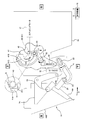
- FIG. 2 is a view showing a peripheral portion of the hopper gate opening / closing mechanism according to the embodiment of the present invention.
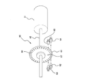
- FIG. 3 is a diagram schematically showing a configuration example of a rotary encoder used in the hopper gate opening / closing mechanism of the embodiment of the present invention.
- FIG. 4 is a diagram used for explaining the operation of the hopper gate opening / closing mechanism of the weighing hopper of FIG.
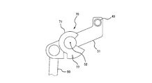
- FIG. 5 is a diagram illustrating an example of a main part of the hopper gate opening / closing mechanism according to the first modification.
- the hopper gate opening / closing mechanism of this embodiment performs a combination calculation based on the weight of the object to be weighed, and uses the hopper gate opening / closing mechanism used in a combination weigher for obtaining a combination in which the total weight of the object to be weighed is a value within an allowable range with respect to the target weight.
- An actuator that generates a driving force for opening and closing the hopper gate, a transmission mechanism that is used to transmit the driving force to the hopper gate, and a detection that can detect the origin of the rotation shaft of the transmission mechanism that corresponds to the position at which the hopper gate is closed Means and a control device capable of receiving the output signal of the detection means.
- control device of the hopper gate opening / closing mechanism of the present embodiment can predict the biting of the object to be weighed into the hopper gate when the hopper gate is opened / closed using the cam mechanism as described above.
- the following specific description only exemplifies a characteristic form of the hopper gate opening / closing mechanism. That is, when the following specific examples are described with appropriate reference numerals attached to the same or corresponding terms as the terms specifying the hopper gate opening / closing mechanism, the specific device corresponds to the hopper gate opening / closing mechanism corresponding thereto. It is an example of the component of.
- the output shaft 42 of the stepping motor 31 is described as an example of the “rotation shaft of the transmission mechanism” that identifies the hopper gate opening / closing mechanism, but the “rotation shaft of the transmission mechanism” is not limited thereto.
- Another example of the “rotating shaft of the transmission mechanism” is described in Modification 1 described later.
- FIG. 1 is a schematic view showing an example of a combination weigher incorporating a hopper gate opening / closing mechanism according to an embodiment of the present invention.
- the combination weigher 100 is provided with a conical dispersion feeder 11 in the center of the upper part of the device, which disperses the object to be weighed supplied from an external supply device (not shown) radially by vibration. It has been.
- a plurality of linear feeders 12 are arranged in a circle.
- a plurality of supply hoppers 13 and a plurality of weighing hoppers 14 are respectively provided below the linear trough 12A of the linear feeder 12 so as to correspond to the linear feeder 12, and around the center base body 17 (main body). Are arranged in a circle with an interval of.
- the object to be weighed sent from the dispersion feeder 11 is vibrated and conveyed on the straight trough 12A of the linear feeder 12 by the vibration of the vibrating body 12B of the linear feeder 12, and sent to each supply hopper 13.
- the supply hopper 13 is provided with a hopper main body 13B and a hopper gate 13A for temporarily holding an object to be weighed sent from the straight trough 12A of the linear feeder 12 and discharging the object to be weighed to the weighing hopper 14 arranged therebelow.
- the weighing hopper 14 includes a hopper body 14 ⁇ / b> B and a hopper gate 14 ⁇ / b> A for temporarily holding an object to be weighed supplied from the upper supply hopper 13 and discharging the object to be weighed to the collecting chute 16.
- the weighing hopper 14 is connected to a load cell 32 (see FIG. 2) corresponding to each of the weighing hoppers 14.
- a load signal (electric signal) output from each of the load cells 32 is input to the control device 18.
- a funnel-shaped collecting chute 16 is disposed below the weighing hopper 14.
- An object to be weighed which is selected as a discharge combination of the combination weigher 100 and is discharged from the weighing hopper 14, slides down on the collecting chute 16 and is discharged from the lower discharge port 16A to, for example, a packaging machine (not shown).
- the control device 18 includes, for example, a microcontroller including a CPU and a ROM and RAM memory in which an operation program and operation parameters of the CPU are stored.
- the operation of the entire combination weigher 100 is controlled by the CPU of the control device 18 executing the operation program stored in the ROM. That is, the control device 18 controls the vibration amplitudes of the dispersion feeder 11 and the linear feeder 12 and their operation times. Further, the control device 18 controls the operation of an actuator (stepping motor 31 and the like described later) for opening and closing the hopper gate 13A of the supply hopper 13 and the hopper gate 14A of the weighing hopper 14.
- an actuator stepping motor 31 and the like described later
- the control device 18 receives a load signal output from the load cell 32 to which the weighing hopper 14 is attached, and calculates a weight of an object to be weighed held by the weighing hopper 14 based on the load signal. Function as.
- the control device 18 also functions as a combination unit that performs combination processing. In this combination processing, a combination calculation is performed based on the calculated weight of the weighing object, and the total weight of the weighing object is within a predetermined weight range (allowable range with respect to the target weight). Find a combination close to weight.
- the combination of the weighing hoppers 14 holding the objects to be weighed corresponding to the combinations obtained in this way is set as the discharge combination.
- control device 18 can also serve as a weighing object biting prediction means for predicting the biting of the object to be weighed into the hopper gate 13A of the supply hopper 13 and the biting of the object to be weighed into the hopper gate 14A of the weighing hopper 14. Although functioning, the details of this means will be described later.
- the control device 18 discharges the object to be weighed from the weighing hopper 14 by opening and closing the hopper gate 14A of the weighing hopper 14 selected as the discharge combination at a predetermined timing.
- the weighing object is supplied from the upper supply hopper 13 to the weighing hopper 14 which has been emptied by discharging the object.
- the empty supply hopper 13 is supplied with an object to be weighed from the straight trough 12A of the linear feeder 12 above the supply hopper 13.
- control device 18 is not necessarily configured by a single control device, and a plurality of control devices are distributed and configured to control the operation of the combination weigher 100 in cooperation with each other. May be.
- the weight calculation means, the combination means, and the weighing object biting prediction means are configured by a single control device 18 is shown here.
- the calculation means, the combination means, and the object-to-be-measured object biting prediction means may each be configured by a separate control device (CPU).
- a center base body 17 which is supported by, for example, four legs (not shown) and corresponds to the main body of the combination weigher 100, is disposed at the center. Yes.
- the center base body 17 has a substantially inverted polygonal frustum shape composed of a lower wall 17A, an upper wall 17B, and a side wall 17C (for example, an inverted regular number of sides corresponding to the number of the weighing hoppers 14). It has an external shape such as a truncated pyramid.
- the combination weigher 100 includes an actuator unit 19 that opens and closes a hopper gate 13 ⁇ / b> A of the supply hopper 13 and a hopper gate 14 ⁇ / b> A of the weighing hopper 14.
- the actuator unit 19 is attached to the side wall 17C of the center base 17 as shown in FIG.
- a partition plate 17 ⁇ / b> D that partitions the inside of the center base body 17 in the horizontal direction is disposed in the center base body 17.
- the center base 17 includes a lower unit housing chamber 17L used for housing the actuator unit 19 and an upper feeder housing chamber 17H used for housing the vibrating body 12B of the linear feeder 12.
- the attachment portion 19 ⁇ / b> A of the actuator unit 19 is formed along the side wall 17 ⁇ / b> C.
- the actuator unit 19 is fixed to the side wall 17C so that the drive unit portion can be accommodated in the unit accommodating chamber 17L.
- the present embodiment is characterized by the hopper gate opening / closing mechanism of the actuator unit 19.
- FIG. 2 is a view showing a peripheral portion of the hopper gate opening / closing mechanism according to the embodiment of the present invention.
- FIG. 2 the direction in which gravity acts is shown as “up and down direction”, and the direction perpendicular to this direction is shown as “left and right direction”.
- these “up”, “down”, and “left” , “Right” may be used to describe the configuration and operation of the hopper gate opening / closing mechanism.
- FIG. 2 for convenience, only the hopper gate opening / closing mechanism of the weighing hopper 14 is illustrated, and the hopper gate opening / closing mechanism of the supply hopper 13 is omitted.
- the members constituting the first cam mechanism, the link mechanism, the second cam mechanism, and the like described below are respectively arranged on both sides of the weighing hopper 14 and configured in pairs. Then, illustration of the members arranged on the depth side of the drawing among the members forming these pairs is omitted.
- a stepping motor 31 (actuator) and a load cell 32 connected to the weighing hopper 14 are arranged in the actuator unit 19.
- the hopper gate opening / closing mechanism of the weighing hopper 14 includes a first cam mechanism disposed outside the actuator unit 19, a second cam mechanism disposed within the actuator unit 19, and a link mechanism disposed within the actuator unit 19. .
- the first cam mechanism includes a cam 21 and a cam follower 23.
- the link mechanism includes a first link member 50 and a second link member 51.
- the second cam mechanism includes a cam 41 and a cam follower 43.
- Each of these mechanisms constitutes a transmission mechanism used to transmit the driving force of the stepping motor 31 to the hopper gate 14A of the weighing hopper 14.
- the hopper gate opening / closing mechanism of the weighing hopper 14 includes a stepping motor 31 that generates a driving force for opening and closing the hopper gate 14A of the weighing hopper 14, and a stepping motor 31 corresponding to a position where the hopper gate 14A is closed.
- a rotary encoder 60 capable of detecting the origin of the output shaft 42 and a control device 18 capable of receiving an output signal of the rotary encoder 60 are provided, and the control device 18 functions as an object biting prediction unit here. The details will be described later.
- the weighing hopper 14 includes a hopper gate 14 ⁇ / b> A supported so as to be rotatable about a support shaft 26.
- An operation plate 25 projects from the outer surface of the hopper gate 14A, and a cam follower 23 is attached to the tip of the operation plate 25.
- the bracket 24 is connected to the hopper body 14B of the weighing hopper 14 at the support shaft 26, and is also attached to a hanger (not shown) fixed to the wall of the actuator unit 19. Thereby, the hopper gate 14A of the weighing hopper 14 can be opened and closed while the hopper body 14B of the weighing hopper 14 is supported.
- the base end portion of the cam 21 is connected to the lower support shaft 22 of the actuator unit 19 using appropriate fixing means (for example, fastening bolts).
- the cam follower 23 is in contact with the cam curved surface 21B at the front end portion of the cam 21.
- the front end portion of the cam 21 is formed by bending two fork-shaped thin members upward,
- the surface of the curved portion that faces the cam follower 23 is the cam curved surface 21B.
- the cam follower 23 is configured not to roll on the cam curved surface 21B of the cam 21 at the position (the position shown in FIG. 2) where the hopper gate 14A is closed.
- the radius of curvature of the cam curved surface 21B of the cam 21 is set so that the movement of the cam follower 23 is regulated by the cam curved surface 21B of the cam 21.
- the cam curved surface 21B of the cam 21 functions as a stopper portion of the hopper gate 14A.
- an arched cam 41 of the second cam mechanism is attached to an output shaft 42 (motor shaft; an example of a rotation shaft of the transmission mechanism) of the stepping motor 31 that suspends the stepping motor 31.
- a rotary plate 61 of the rotary encoder 60 is attached to the output shaft 42 of the stepping motor 31.
- the detailed configuration of the rotary encoder 60 will be described later.
- an elongated strip-shaped and arch-shaped cut region 41 ⁇ / b> A is formed at the peripheral edge of the cam 41.
- the pair of opposing curved surfaces at the notch 41A function as first and second cam curved surfaces 41B and 41C (details will be described later) of the cam 41, whereby the second cam mechanism has a double cam structure. Yes.
- a plate-like and strip-like first link member 50 is arranged so as to stand in the vertical direction, and its lower end is supported at the peripheral portion of the support shaft 22. It is connected to the shaft 22, and its upper end is connected to the left end of the plate-like and substantially Z-shaped second link member 51.
- the second link member 51 is connected to the support shaft 52 at the center thereof, and the cam follower 43 is disposed at the right end of the second link member 51.
- the second link member 51 can move substantially in a seesaw shape by rotating the second link member 51 around the support shaft 52.
- the cam follower 43 connected to the right end of the second link member 51 moves in the vertical direction
- the left end of the second link member 51 moves in the vertical direction and the cam follower 43 moves. Move in the opposite direction.
- the second link member 51 is applied with an urging force by using an appropriate urging means (not shown; for example, a spring), and the cam follower 43 hits the cam 41 at a position where the hopper gate 14A is closed.
- the movement of the link mechanism is stopped by appropriate stopper means (not shown) so as not to be present.
- a gap S (see an enlarged view of FIG. 2) is formed between the cam 41 and the cam follower 43 when the hopper gate 14A is closed.
- the gap between the cam 41 and the cam follower 43 is cut off.
- the vibration of the drive system (stepping motor 31 or the like) of the combination weigher 100 from being transmitted to the load cell 32 via the weighing hopper 14.
- FIG. 3 is a diagram schematically showing a configuration example of a rotary encoder used in the hopper gate opening / closing mechanism of the embodiment of the present invention.
- the rotary encoder 60 is a kind of sensor that converts the mechanical displacement amount of the rotation of the output shaft 42 of the stepping motor 31 into a digital amount. Arranged on the output shaft 42. That is, the rotary encoder 60 includes a disk-shaped rotating plate 61 that rotates with the output shaft 42, a pair of light emitting elements 62 and 63, and a pair of light receiving elements 64 and 65.
- a large number of minute slits 66 for stepping motor control signals are formed at equal intervals along the periphery of the rotating plate 61 at the periphery of the rotating plate 61.
- These slits 66 are arranged on the rotating plate 61 so that the light emitted from the light emitting element 62 can intermittently pass through each of the slits 66 when the rotating plate 61 rotates. Then, whenever the outgoing light passes through the slit 66 during rotation of the rotating plate 61, the outgoing light enters the light receiving element 64, and a pulse signal is detected by the light receiving element 64, and the light receiving element 64 controls this pulse signal. Output to the device 18.
- the control apparatus 18 can receive the pulse signal (output signal of the light receiving element 64) detected by the light receiving element 64, and can measure the rotation angle of the output shaft 42 of the stepping motor 31 based on this pulse signal.
- the stepping motor 31 can be feedback controlled. That is, the control device 18 synchronizes the input pulse to the stepping motor 31 and the rotation of the output shaft 42 of the stepping motor 31 (for example, for each input pulse to the stepping motor 31, The stepping motor 31 is controlled so that the output shaft 42 rotates about 0.9 °.
- control device 18 detects the rotation angle of the output shaft 42 as the pulse signal, and links (feeds back) the detected value to the rotation operation of the output shaft 42 to thereby change the rotation operation of the output shaft 42 to a predetermined value. It keeps in.
- one fine slit 67 for origin signal is formed at an appropriate position between the peripheral edge portion and the central portion of the rotating plate 61.
- the slit 67 is arranged on the rotating plate 61 so that the light emitted from the light emitting element 63 can pass through the slit 67 only once per rotation when the rotating plate 61 rotates. Then, when the rotating plate 61 rotates, the emitted light enters the light receiving element 65 every time the rotating plate 61 rotates, and the light receiving element 65 detects a pulse signal, and the light receiving element 64 controls the pulse signal. 18 is output.
- this pulse signal is generated only once per rotation of the rotating plate 61, it can be used for detecting the origin within the rotation of the rotating plate 61.
- the arrangement of the slit 67 is set so that the position where the hopper gate 14A is closed corresponds to the origin in the rotation of the rotating plate 61. Then, the control device 18 receives a signal (an output signal of the light receiving element 65) detected by the light receiving element 65, and based on this signal, the output shaft 42 of the stepping motor 31 corresponding to the position where the hopper gate 14A is closed.
- the origin that is, the origin within the rotation of the rotating plate 61
- FIG. 4 is a diagram used for explaining the operation of the hopper gate opening / closing mechanism of the weighing hopper of FIG.
- the cam 41 of the second cam mechanism rotates in the direction of arrow E around the center of the output shaft 42 based on the driving force of the stepping motor 31, the cam follower 43. However, it rolls into the incision area 41A between the first cam curved face 41B and the second cam curved face 41C and enters the area 41A. That is, the cam 41 is configured so that the cam follower 43 can be guided to the cut region 41A while the hopper gate 14A is being opened and closed.
- the protruding portion of the first cam curved surface 41B has a biasing force that overcomes the biasing force of the spring based on the driving force of the stepping motor 31.
- cam follower 43 the protruding portion of the first cam curved surface 41B can forcibly push down the cam follower 43 downward.
- the cam follower 43 moves in the direction of the arrow F (that is, moves down in the vertical direction).
- the second link member 51 rotates in the direction of arrow G about the support shaft 52.
- the second link member 51 moves clockwise in a substantially seesaw shape.
- the first link member 50 moves in the direction of the arrow H (that is, moves up in the vertical direction).
- the cam 21 can rotate in the direction of arrow C around the central portion of the support shaft 22.
- the second cam mechanism can convert the rotational motion of the stepping motor 31 into the linear motion of the first link member 50 of the link mechanism, and the first cam mechanism can linearly move the first link member 50 of the link mechanism. Can be converted into an opening / closing motion of the hopper gate 14A.
- the cam 41 moves in the reverse direction E ′ of the arrow E around the center of the output shaft 42 based on the driving force of the stepping motor 31.
- the cam follower 43 retreats from the region 41A while rolling on the cut region 41A between the first cam curved surface 41B and the second cam curved surface 41C.
- the cam follower 43 comes into contact with the second cam curved surface 41C of the cam 41, so that the second cam curved surface 41C generates a biasing force that complements the biasing action of the spring based on the driving force of the stepping motor 31. 43.
- the second cam curved surface 41C can forcibly push up the cam follower 43 upward.
- the cam follower 43 moves in the reverse direction F ′ of the arrow F (that is, moves up in the vertical direction).
- the second link member 51 rotates about the support shaft 52 in the reverse direction G ′ of the arrow G.
- the second link member 51 moves counterclockwise in a substantially seesaw shape.
- the first link member 50 moves in the reverse direction H ′ of the arrow H (that is, moves down in the vertical direction).
- the cam 21 can rotate in the reverse direction C ′ of the arrow C around the central portion of the support shaft 22.
- the second cam mechanism can convert the rotational motion of the stepping motor 31 into the linear motion of the first link member 50 of the link mechanism, and the first cam mechanism can linearly move the first link member 50 of the link mechanism. Can be converted into an opening / closing motion of the hopper gate 14A.
- the first cam mechanism of the hopper gate opening / closing mechanism is configured to serve as the stopper portion of the hopper gate 14A by the cam follower 23 and the cam 21.
- the cam follower 23 corresponds to the driven node of the first cam mechanism
- the cam 21 corresponds to the driving node of the first cam mechanism.
- the second cam mechanism of the hopper gate opening / closing mechanism is configured such that the hopper gate 14A can be forcibly opened and closed by the cam follower 43 and the cam 41 using the driving force of the stepping motor 31.
- the cam follower 43 corresponds to the follower node of the second cam mechanism
- the cam 41 corresponds to the drive node of the second cam mechanism.
- the hopper gate opening / closing mechanism has the following various effects.
- the hopper gate 14A can be appropriately opened and closed based on the driving force of the stepping motor 31 by the cooperation of the first cam mechanism and the second cam mechanism.
- the hopper gate 14A is prevented from opening at the position where the hopper gate 14A is closed by the first cam mechanism (cam curved surface 21B of the cam 21). Therefore, in this hopper gate opening / closing mechanism, a special mechanism for locking and releasing the conventional stopper portion (for example, a conventional toggle link mechanism) is used by using the first cam mechanism as the stopper portion of the hopper gate 14A. It becomes unnecessary. Further, it is possible to avoid an increase in the motor torque of the stepping motor 31 that occurs with the lock and release of the conventional stopper portion. Furthermore, since the number of parts of the stopper portion of the hopper gate 14A can be reduced, the stopper portion can be configured simply.
- the second cam mechanism ( The cam follower 43 can be forcibly pushed upward by the contact between the second cam curved surface 41 ⁇ / b> C) of the cam 41 and the cam follower 43.
- the hopper gate opening / closing mechanism of the present embodiment the hopper gate 14A is closed using the driving force of the stepping motor 31, so that the hopper gate 14A is compared with the case where the hopper gate is closed using only the biasing action of the conventional spring. Can be closed at high speed.
- control device 18 for the hopper gate opening / closing mechanism of the present embodiment is to be weighed to the hopper gate 14A when the hopper gate 14A using the second cam mechanism is opened / closed by the cooperation of the rotary encoder 60 and the second cam mechanism. Predict the biting of things.
- the hopper gate opening / closing mechanism of the present embodiment is such that when the hopper gate 14A is opened, the urging force acts between the cam 41 (first cam curved surface 41B) and the cam follower 43, and when the hopper gate 14A is closed, the cam 41 (second cam curved surface 41 ⁇ / b> C) and the cam follower 43 are configured to exert a biasing force. That is, the cam follower 43 is in contact with the first cam curved surface 41B and the second cam curved surface 41C of the cam 41 during the opening and closing of the hopper gate 14A.
- the control device 18 can detect the step-out of the stepping motor 31 based on the output signal of the rotary encoder 60, and thus can predict the biting of the object to be weighed into the hopper gate 14A.
- the cam follower 43 and the first cam curved surface 41B come into contact with each other.
- the cam 41 cannot return to the state corresponding to the position at which the hopper gate 14A is closed. That is, the energizing force between the second cam curved surface 41C of the cam 41 and the cam follower 43 when the object to be weighed into the hopper gate 14A is engaged.
- the output shaft 42 of the stepping motor 31 has the origin of the output shaft 42 corresponding to the position where the hopper gate 14A is closed even though the origin return pulse of the output shaft 42 is input to the stepping motor 31. Returning to is prevented. As a result, the stepping motor 31 steps out.
- the control device 18 controls the stepping motor 31 so as to close the hopper gate 14A when the object to be weighed in the hopper gate 14A is received, the light reception of the rotary encoder 60 is received. No signal is detected at element 65. For this reason, the control device 18 detects, based on the output signal of the rotary encoder 60, that the output shaft 42 has not returned to the origin of the output shaft 42 corresponding to the position where the hopper gate 14A is closed when the hopper gate 14A is closed. it can. Therefore, the control device 18 can predict the biting of the object to be weighed into the hopper gate 14A based on the output signal of the rotary encoder 60.
- the hopper gate opening / closing mechanism of the present embodiment when the hopper gate 14A is closed, the contact between the cam 41 and the cam follower 41 is released, and a gap S is formed between the cam follower 43 and the cam 41. As a result, the edge between the cam follower 43 and the cam 41 is cut off. For this reason, when the hopper gate 14 ⁇ / b> A is closed, vibrations of the drive system (stepping motor 31 and the like) of the combination weigher 100 can be prevented from being transmitted to the load cell 32 via the weighing hopper 14. Thereby, the weight of the object to be weighed in the weighing hopper 14 can be appropriately measured using the load cell 32.
- the hopper gate opening / closing mechanism of the supply hopper 13 has the same configuration as the hopper gate opening / closing mechanism of the weighing hopper 13 described above, and has the same effects as the above-described effects. Play. However, since the supply hopper 13 is not connected to the load cell 32, it is not always necessary to cut the edge (details will be described later) between the cam of the second cam mechanism and the cam follower.
- an origin sensor capable of detecting the position where the hopper gate 14A is closed is provided in addition to the rotary encoder 60, thereby eliminating the above-mentioned drawbacks.
- FIG. 5 is a diagram illustrating an example of a main part of the hopper gate opening / closing mechanism according to the first modification.
- the hopper gate opening / closing mechanism of this modification includes an origin sensor 70, and a rotating plate 71 of the origin sensor 70 is attached to a support shaft 52 of the link mechanism. That is, the origin sensor 70 includes a rotating plate 71 that rotates together with the support shaft 52, a light emitting element (not shown), and a light receiving element (not shown). Further, as shown in FIG. 5, one fine slit 77 for the origin detection signal is formed in the peripheral portion of the rotating plate 71. The slit 77 is disposed on the rotating plate 71 so that light emitted from the light emitting element can pass through the slit 77 at a position where the hopper gate 14A is closed.
- the control device 18 receives a signal (output signal of the light receiving element) detected by the light receiving element, and can detect the origin of the support shaft 52 of the link mechanism corresponding to the position where the hopper gate 14A is closed based on this signal. That is, the control device 18 detects the closed position of the hopper gate 14A as the signal, and can thereby detect the origin of the output shaft 42 corresponding to the position where the hopper gate 14A is closed.
- the control device 18 uses an extremely thin object to be measured (for example, a potato chip) as a hopper gate. 14A (even when the cam follower 43 forms a free end of the link mechanism without contacting the first cam curved surface 41B and the second cam curved surface 41C). Based on the output signal, the biting of the object to be weighed into the hopper gate 14A can be predicted.
- an extremely thin object to be measured for example, a potato chip
- a rotating plate (not shown) of the same type of sensor as the origin sensor 70 may be provided on the support shaft 22 (see FIG. 2) of the cam 21. Thereby, there can exist the same effect as the above.
- the hopper gate opening / closing mechanism of the weighing hopper 14 of the present embodiment is configured to open in one counterclockwise direction, but is not limited thereto.
- the weighing hopper may include a pair of hopper gates, and a hopper gate opening / closing mechanism may be used so that one of the pair of hopper gates opens clockwise and the other opens counterclockwise.
- the pair of hopper gates may be coupled to the output shaft 42 of the stepping motor 31 using an appropriate coupling member (not shown).
- the control device 18 can predict the biting of the object to be weighed into each of the pair of hopper gates using the single rotary encoder 60.
- the hopper gate opening / closing mechanism of the weighing hopper 14 of the present embodiment the example in which the front end portion of the cam 21 is formed by bending two fork-like thin members upward is described.
- an example has been described in which an elongated strip-shaped and arch-shaped cut region 41 ⁇ / b> A is formed at the peripheral edge of the arch-shaped cam 41.
- the shapes of the cam 21 and the cam 41 are not limited to this.
- this disk member can be used as an alternative cam of the cam 21.
- this disk member can be used as an alternative cam for the cam 41.
- the motor torque of the stepping motor 31 may be increased compared to the hopper gate opening / closing mechanism of the present embodiment.
- the hopper gate opening / closing mechanism of the weighing hopper 14 is illustrated, but the present invention is not limited to this.
- the hopper gate opening / closing mechanism of this embodiment can be applied to the hopper gate opening / closing of such a memory hopper.
- the present invention provides a hopper gate opening / closing mechanism that can predict the biting of an object to be weighed into the hopper gate when the hopper gate is opened / closed using a cam mechanism. Therefore, the present invention can be used for a hopper gate opening / closing mechanism of various combination weighers used for weighing objects to be weighed.
- Dispersion feeder 12 Linear feeder 12A Straight traveling trough 12B Vibrating body 13 Supply hopper 13A Supply hopper hopper gate 13B Supply hopper hopper body 14 Weigh hopper 14A Weigh hopper hopper gate 14B Weigh hopper hopper body 16 Collecting chute 16A Discharge port 17 Center base ( Body) 17A Lower wall 17B Upper wall 17C Side wall 17D Partition plate 17H Feeder storage chamber 17D Unit storage chamber 18 Controller 19 Actuator unit 19A Mounting portion 21 Cam of first cam mechanism 21B Cam curved surface 22 of first cam mechanism Cam of first cam mechanism Support shaft 23 Cam follower 24 of the first cam mechanism Bracket 25 Actuator plate 26 of the weighing hopper Support shaft 31 of the weighing hopper Stepping motor 32 Load cell 41 Cam 41A of the second cam mechanism Infeed region 41B First cam of the cam of the second cam mechanism Curved surface 41C Second cam curved surface 42 of cam of second cam mechanism Output shaft 43 Cam follower 50 of second cam mechanism First link member 51 Second link member 52 Support shaft 60 of link mechanism
Landscapes
- Physics & Mathematics (AREA)
- General Physics & Mathematics (AREA)
- Weight Measurement For Supplying Or Discharging Of Specified Amounts Of Material (AREA)
- Filling Or Emptying Of Bunkers, Hoppers, And Tanks (AREA)
- Transmission Devices (AREA)
Abstract
Description
ホッパゲートの開閉用の駆動力を発生するアクチュエータと、
前記ホッパゲートへの前記駆動力の伝達に用いる伝達機構と、
前記ホッパゲートが閉まる位置に対応する前記伝達機構の回転軸の原点を検出可能な検出手段と、
前記検出手段の出力信号を受け取ることができる制御装置と、を備えるホッパゲート開閉機構を提供する。
まず、本発明の実施形態のホッパゲート開閉機構の特徴的な形態について述べる。
[組合せ秤の構成例]
まず、組合せ秤100の全体構成について図面を参照しながら概説する。
[ホッパゲート開閉機構の構成例]
図2は、本発明の実施形態のホッパゲート開閉機構の周辺部を示した図である。
[ロータリエンコーダの構成]
次に、ロータリエンコーダ60の構成例について図面を参照しながら述べる。
[ホッパゲート開閉機構の動作例]
次に、計量ホッパ14のホッパゲート開閉機構の動作例について図面を参照しながら詳しく説明する。なお、供給ホッパ13のホッパゲート開閉機構の動作については、以下の説明により容易に理解できるので、ここでは、省略する。
つまり、ホッパゲート14Aへの被計量物の噛み込み時において、カム41の第2カム曲面41Cとカムフォロア43との間に付勢力が作用することにより、ステッピングモータ31の出力軸42は、出力軸42の原点復帰用パルスがステッピングモータ31に入力されているにも関わらず、ホッパゲート14Aが閉まる位置に対応する出力軸42の原点に復帰することが阻止されている。これにより、ステッピングモータ31が脱調する。
[変形例1]
本実施形態のホッパゲート開閉機構では、ホッパゲート14Aが閉まる位置に対応するステッピングモータ31の出力軸42の原点検出にロータリエンコーダ60を用い、制御装置18が、ロータリエンコーダ60の出力信号に基づいて、ホッパゲート14Aへの被計量物の噛み込みを予測できる例を述べたが、この手法には、以下の欠点がある。
[変形例2]
本実施形態の計量ホッパ14のホッパゲート開閉機構では、計量ホッパ14のホッパゲート14Aは、反時計回りの1方向に開くように構成されているが、これに限らない。例えば、計量ホッパが、一対のホッパゲートを備え、ホッパゲート開閉機構を用いて、ホッパゲートの対の一方が、時計回りに開き、他方が反時計回りに開くように構成してもよい。そして、この場合、適宜の連結部材(図示せず)を用いて、ホッパゲートの対のそれぞれに、ステッピングモータ31の出力軸42に連結させるとよい。これにより、制御装置18は、単一のロータリエンコーダ60を用いて、上記ホッパゲートの対のそれぞれへの被計量物の噛み込みを予測できる。
[変形例3]
本実施形態の計量ホッパ14のホッパゲート開閉機構では、カム21の前端部を、フォーク状の2本の細い部材を上方に湾曲して形成する例を述べた。また、アーチ状のカム41の周縁部において、細長い短冊状かつアーチ状の切り込み領域41Aを形成する例を述べた。しかし、これらのカム21およびカム41の形状は、これに限らない。
[変形例4]
本実施形態では、計量ホッパ14のホッパゲート開閉機構が例示されているが、これに限らない。
12 リニアフィーダ
12A 直進トラフ
12B 振動体
13 供給ホッパ
13A 供給ホッパのホッパゲート
13B 供給ホッパのホッパ本体
14 計量ホッパ
14A 計量ホッパのホッパゲート
14B 計量ホッパのホッパ本体
16 集合シュート
16A 排出口
17 センター基体(本体)
17A 下壁
17B 上壁
17C 側壁
17D 仕切板
17H フィーダ収容室
17D ユニット収容室
18 制御装置
19 アクチュエータユニット
19A 取り付け部
21 第1カム機構のカム
21B 第1カム機構のカム曲面
22 第1カム機構のカムの支軸
23 第1カム機構のカムフォロア
24 ブラケット
25 計量ホッパの作動板
26 計量ホッパの支軸
31 ステッピングモータ
32 ロードセル
41 第2カム機構のカム
41A 切り込み領域
41B 第2カム機構のカムの第1カム曲面
41C 第2カム機構のカムの第2カム曲面
42 出力軸
43 第2カム機構のカムフォロア
50 第1リンク部材
51 第2リンク部材
52 リンク機構の支軸
60 ロータリエンコーダ
61 ロータリエンコーダの回転板
62、63 発光素子
64、65 受光素子
66、67 ロータリエンコーダのスリット
70 原点センサ
71 原点センサの回転板
77 原点センサのスリット
100 組合せ秤
Claims (8)
- 被計量物の重量に基づいて組合せ演算を行い、前記被計量物の重量の合計が目標重量に対する許容範囲内の値になる組合せを求める組合せ秤に用いるホッパゲート開閉機構であって、
ホッパゲートの開閉用の駆動力を発生するアクチュエータと、
前記ホッパゲートへの前記駆動力の伝達に用いる伝達機構と、
前記ホッパゲートが閉まる位置に対応する前記伝達機構の回転軸の原点を検出可能な検出手段と、
前記検出手段の出力信号を受け取ることができる制御装置と、を備えるホッパゲート開閉機構。 - 前記伝達機構は、前記アクチュエータの回転運動をリンク機構の直線運動に変換するカム機構を含み、
前記カム機構の原動節が、前記アクチュエータを懸架する前記アクチュエータの出力軸に取り付けられ、
前記カム機構の従動節が、前記リンク機構に取り付けられている請求項1に記載のホッパゲート開閉機構。 - 前記原動節は、前記ホッパゲートが開くときの前記従動節への前記駆動力の伝達に用いる第1カム曲面と、前記ホッパゲートが閉まるときの前記従動節への前記駆動力の伝達に用いる第2カム曲面と、を備える請求項2に記載のホッパゲート開閉機構。
- カムフォロアが、前記従動節として用いられ、前記カムフォロアが当接するカムが、前記原動節として用いられ、
前記カムは、前記ホッパゲートの開閉途中において、前記第1カム曲面と前記第2カム曲面との間の領域に前記カムフォロアを案内するように構成されている請求項3に記載のホッパゲート開閉機構 - 前記検出手段および前記カムは、前記回転軸としての前記アクチュエータの出力軸に取り付けられ、
前記ホッパゲートへの前記被計量物の噛み込み時において、前記カムと前記カムフォロアとの間に付勢力が作用することにより、前記出力軸が、前記ホッパゲートが閉まる位置に対応する前記出力軸の原点に復帰することが阻止されているときは、前記制御装置は、前記検出手段の出力信号に基づいて、前記ホッパゲートへの前記被計量物の噛み込みを予測する、請求項4に記載のホッパゲート開閉機構。 - 前記検出手段は、ロータリエンコーダである請求項5に記載のホッパゲート開閉機構。
- 前記検出手段は、前記回転軸としての前記リンク機構の支軸に取り付けられ、
前記ホッパゲートへの前記被計量物の噛み込み時において、前記カムフォロアが、前記第1カム曲面および前記第2カム曲面の何れにも接触せずに、前記リンク機構の自由端を構成するときは、前記制御装置は、前記検出手段の出力信号に基づいて、前記ホッパゲートへの前記被計量物の噛み込みを予測する、請求項4に記載のホッパゲート開閉機構。 - 前記検出手段は、原点センサである請求項7に記載のホッパゲート開閉機構。
Priority Applications (6)
| Application Number | Priority Date | Filing Date | Title |
|---|---|---|---|
| CN201180040185.3A CN103052869B (zh) | 2011-04-05 | 2011-04-05 | 料斗闸门开闭机构 |
| PCT/JP2011/002021 WO2012137250A1 (ja) | 2011-04-05 | 2011-04-05 | ホッパゲート開閉機構 |
| US14/009,496 US9523601B2 (en) | 2011-04-05 | 2011-04-05 | Hopper gate opening and closing mechanism |
| EP11863088.8A EP2696179B1 (en) | 2011-04-05 | 2011-04-05 | Mechanism for opening and closing hopper gate |
| ES11863088.8T ES2593756T3 (es) | 2011-04-05 | 2011-04-05 | Mecanismo para abrir y cerrar una compuerta de tolva |
| JP2012549193A JP5389276B2 (ja) | 2011-04-05 | 2011-04-05 | ホッパゲート開閉機構 |
Applications Claiming Priority (1)
| Application Number | Priority Date | Filing Date | Title |
|---|---|---|---|
| PCT/JP2011/002021 WO2012137250A1 (ja) | 2011-04-05 | 2011-04-05 | ホッパゲート開閉機構 |
Publications (1)
| Publication Number | Publication Date |
|---|---|
| WO2012137250A1 true WO2012137250A1 (ja) | 2012-10-11 |
Family
ID=46968699
Family Applications (1)
| Application Number | Title | Priority Date | Filing Date |
|---|---|---|---|
| PCT/JP2011/002021 Ceased WO2012137250A1 (ja) | 2011-04-05 | 2011-04-05 | ホッパゲート開閉機構 |
Country Status (6)
| Country | Link |
|---|---|
| US (1) | US9523601B2 (ja) |
| EP (1) | EP2696179B1 (ja) |
| JP (1) | JP5389276B2 (ja) |
| CN (1) | CN103052869B (ja) |
| ES (1) | ES2593756T3 (ja) |
| WO (1) | WO2012137250A1 (ja) |
Cited By (1)
| Publication number | Priority date | Publication date | Assignee | Title |
|---|---|---|---|---|
| CN106032993A (zh) * | 2015-03-11 | 2016-10-19 | 山东新北洋信息技术股份有限公司 | 罩门位置检测方法及装置和纸币处理装置 |
Families Citing this family (3)
| Publication number | Priority date | Publication date | Assignee | Title |
|---|---|---|---|---|
| CN103353339B (zh) * | 2013-07-01 | 2015-12-09 | 安徽正远包装科技有限公司 | 一种自锁式称量斗机构 |
| US10723492B2 (en) * | 2017-09-21 | 2020-07-28 | Yamato Corporation | Depositor apparatus |
| KR102887781B1 (ko) * | 2025-09-03 | 2025-11-18 | (주)광산 | 공정 불량 플라스틱 성형물 재활용 시스템 |
Citations (8)
| Publication number | Priority date | Publication date | Assignee | Title |
|---|---|---|---|---|
| JPH10122943A (ja) * | 1996-10-22 | 1998-05-15 | Ishida Co Ltd | ローラと溝部との摺動係合機構、並びに該機構を備えるホッパの開閉装置及び該機構をホッパの開閉装置に備える組合せ計量装置 |
| JP2004233193A (ja) * | 2003-01-30 | 2004-08-19 | Ishida Co Ltd | 計量装置 |
| JP3670295B2 (ja) | 1996-07-03 | 2005-07-13 | 株式会社イシダ | ホッパの着脱性を改善した計量装置 |
| JP2006125914A (ja) * | 2004-10-27 | 2006-05-18 | Ishida Co Ltd | 計量装置 |
| JP2006201099A (ja) * | 2005-01-24 | 2006-08-03 | Yamato Scale Co Ltd | 組合せ秤 |
| JP2011007525A (ja) * | 2009-06-23 | 2011-01-13 | Yamato Scale Co Ltd | ホッパゲート開閉装置およびこれを備える計量装置 |
| JP2011013003A (ja) * | 2009-06-30 | 2011-01-20 | Yamato Scale Co Ltd | 組合せ秤 |
| JP2011064489A (ja) * | 2009-09-15 | 2011-03-31 | Yamato Scale Co Ltd | 組合せ秤及び組合せ秤におけるホッパゲートの駆動方法 |
Family Cites Families (7)
| Publication number | Priority date | Publication date | Assignee | Title |
|---|---|---|---|---|
| JPS5972516U (ja) * | 1982-11-08 | 1984-05-17 | 株式会社石田衡器製作所 | 自動計量装置におけるホツパ開閉装置 |
| AU554788B2 (en) * | 1982-12-29 | 1986-09-04 | Kabushiki Kaisha Ishida Koki Seisakusho | Combination weigher discharge apparatus |
| US4705125A (en) * | 1986-11-14 | 1987-11-10 | Ishida Scales Manufacturing Company, Ltd. | Method of and apparatus for controlling hopper gate motion |
| CN2059737U (zh) * | 1989-11-24 | 1990-07-25 | 贾玉山 | 配料斗秤 |
| US5234128A (en) * | 1991-05-13 | 1993-08-10 | Hill Francis K | Aggregate material spreader |
| CN2339979Y (zh) * | 1998-03-31 | 1999-09-22 | 芦殿林 | 带水分检测装置的电子自动秤 |
| DE112010005849B4 (de) * | 2010-09-06 | 2020-10-15 | Yamato Scale Co. Ltd. | Wägeeinheit und Kombinationswaage unter Verwendung derselben |
-
2011
- 2011-04-05 CN CN201180040185.3A patent/CN103052869B/zh active Active
- 2011-04-05 WO PCT/JP2011/002021 patent/WO2012137250A1/ja not_active Ceased
- 2011-04-05 JP JP2012549193A patent/JP5389276B2/ja active Active
- 2011-04-05 EP EP11863088.8A patent/EP2696179B1/en active Active
- 2011-04-05 US US14/009,496 patent/US9523601B2/en active Active
- 2011-04-05 ES ES11863088.8T patent/ES2593756T3/es active Active
Patent Citations (8)
| Publication number | Priority date | Publication date | Assignee | Title |
|---|---|---|---|---|
| JP3670295B2 (ja) | 1996-07-03 | 2005-07-13 | 株式会社イシダ | ホッパの着脱性を改善した計量装置 |
| JPH10122943A (ja) * | 1996-10-22 | 1998-05-15 | Ishida Co Ltd | ローラと溝部との摺動係合機構、並びに該機構を備えるホッパの開閉装置及び該機構をホッパの開閉装置に備える組合せ計量装置 |
| JP2004233193A (ja) * | 2003-01-30 | 2004-08-19 | Ishida Co Ltd | 計量装置 |
| JP2006125914A (ja) * | 2004-10-27 | 2006-05-18 | Ishida Co Ltd | 計量装置 |
| JP2006201099A (ja) * | 2005-01-24 | 2006-08-03 | Yamato Scale Co Ltd | 組合せ秤 |
| JP2011007525A (ja) * | 2009-06-23 | 2011-01-13 | Yamato Scale Co Ltd | ホッパゲート開閉装置およびこれを備える計量装置 |
| JP2011013003A (ja) * | 2009-06-30 | 2011-01-20 | Yamato Scale Co Ltd | 組合せ秤 |
| JP2011064489A (ja) * | 2009-09-15 | 2011-03-31 | Yamato Scale Co Ltd | 組合せ秤及び組合せ秤におけるホッパゲートの駆動方法 |
Non-Patent Citations (1)
| Title |
|---|
| See also references of EP2696179A4 * |
Cited By (2)
| Publication number | Priority date | Publication date | Assignee | Title |
|---|---|---|---|---|
| CN106032993A (zh) * | 2015-03-11 | 2016-10-19 | 山东新北洋信息技术股份有限公司 | 罩门位置检测方法及装置和纸币处理装置 |
| CN106032993B (zh) * | 2015-03-11 | 2019-02-26 | 山东新北洋信息技术股份有限公司 | 罩门位置检测方法及装置和纸币处理装置 |
Also Published As
| Publication number | Publication date |
|---|---|
| ES2593756T3 (es) | 2016-12-13 |
| CN103052869A (zh) | 2013-04-17 |
| EP2696179B1 (en) | 2016-06-29 |
| US20140102229A1 (en) | 2014-04-17 |
| JP5389276B2 (ja) | 2014-01-15 |
| EP2696179A4 (en) | 2014-12-10 |
| JPWO2012137250A1 (ja) | 2014-07-28 |
| EP2696179A1 (en) | 2014-02-12 |
| CN103052869B (zh) | 2014-08-27 |
| US9523601B2 (en) | 2016-12-20 |
Similar Documents
| Publication | Publication Date | Title |
|---|---|---|
| JP5389276B2 (ja) | ホッパゲート開閉機構 | |
| JP5406381B2 (ja) | 組合せ秤 | |
| JP5389272B2 (ja) | ホッパゲート開閉機構 | |
| US9228883B2 (en) | Weighing unit and combination weigher using the same | |
| JP6777357B1 (ja) | 組合せ計量装置 | |
| JP5289205B2 (ja) | 計量ホッパのゲート開閉機構 | |
| JP5410855B2 (ja) | ホッパゲート開閉装置およびこれを備える計量装置 | |
| JP5713796B2 (ja) | コーンバルブ式計量ユニット | |
| JP5858729B2 (ja) | ホッパの開閉機構 | |
| JP6537347B2 (ja) | 組合せ秤 | |
| EP1228988A1 (en) | Combination weighing equipment | |
| JP5731273B2 (ja) | 組合せ計量機のホッパアセンブリ | |
| CN215984820U (zh) | 含不及格重量剔除装置的组合秤 | |
| JP5289216B2 (ja) | 組合せ秤 | |
| RU2724409C1 (ru) | Весовой дозатор для сыпучих материалов | |
| JP4592218B2 (ja) | 計量ホッパ | |
| JP2015141060A (ja) | ホッパ及びそれを用いた組合せ秤 | |
| JP2017026437A (ja) | 組合せ計量装置 | |
| JP4896913B2 (ja) | 計量装置および計量装置におけるホッパゲートの駆動方法 | |
| US579449A (en) | richards | |
| JP2011169678A (ja) | ホッパおよび計量装置 | |
| JP2007119018A (ja) | 計量包装システム |
Legal Events
| Date | Code | Title | Description |
|---|---|---|---|
| WWE | Wipo information: entry into national phase |
Ref document number: 201180040185.3 Country of ref document: CN |
|
| ENP | Entry into the national phase |
Ref document number: 2012549193 Country of ref document: JP Kind code of ref document: A |
|
| 121 | Ep: the epo has been informed by wipo that ep was designated in this application |
Ref document number: 11863088 Country of ref document: EP Kind code of ref document: A1 |
|
| NENP | Non-entry into the national phase |
Ref country code: DE |
|
| WWE | Wipo information: entry into national phase |
Ref document number: 2011863088 Country of ref document: EP |
|
| WWE | Wipo information: entry into national phase |
Ref document number: 14009496 Country of ref document: US |