WO2012137300A1 - Appareil de commande pour moteur électrique, véhicule électrique équipé de ce moteur et procédé de commande du moteur électrique - Google Patents
Appareil de commande pour moteur électrique, véhicule électrique équipé de ce moteur et procédé de commande du moteur électrique Download PDFInfo
- Publication number
- WO2012137300A1 WO2012137300A1 PCT/JP2011/058598 JP2011058598W WO2012137300A1 WO 2012137300 A1 WO2012137300 A1 WO 2012137300A1 JP 2011058598 W JP2011058598 W JP 2011058598W WO 2012137300 A1 WO2012137300 A1 WO 2012137300A1
- Authority
- WO
- WIPO (PCT)
- Prior art keywords
- change
- voltage
- phase
- rectangular wave
- electric motor
- Prior art date
- Legal status (The legal status is an assumption and is not a legal conclusion. Google has not performed a legal analysis and makes no representation as to the accuracy of the status listed.)
- Ceased
Links
Images




Classifications
-
- B—PERFORMING OPERATIONS; TRANSPORTING
- B60—VEHICLES IN GENERAL
- B60L—PROPULSION OF ELECTRICALLY-PROPELLED VEHICLES; SUPPLYING ELECTRIC POWER FOR AUXILIARY EQUIPMENT OF ELECTRICALLY-PROPELLED VEHICLES; ELECTRODYNAMIC BRAKE SYSTEMS FOR VEHICLES IN GENERAL; MAGNETIC SUSPENSION OR LEVITATION FOR VEHICLES; MONITORING OPERATING VARIABLES OF ELECTRICALLY-PROPELLED VEHICLES; ELECTRIC SAFETY DEVICES FOR ELECTRICALLY-PROPELLED VEHICLES
- B60L15/00—Methods, circuits, or devices for controlling the traction-motor speed of electrically-propelled vehicles
- B60L15/20—Methods, circuits, or devices for controlling the traction-motor speed of electrically-propelled vehicles for control of the vehicle or its driving motor to achieve a desired performance, e.g. speed, torque, programmed variation of speed
-
- B—PERFORMING OPERATIONS; TRANSPORTING
- B60—VEHICLES IN GENERAL
- B60L—PROPULSION OF ELECTRICALLY-PROPELLED VEHICLES; SUPPLYING ELECTRIC POWER FOR AUXILIARY EQUIPMENT OF ELECTRICALLY-PROPELLED VEHICLES; ELECTRODYNAMIC BRAKE SYSTEMS FOR VEHICLES IN GENERAL; MAGNETIC SUSPENSION OR LEVITATION FOR VEHICLES; MONITORING OPERATING VARIABLES OF ELECTRICALLY-PROPELLED VEHICLES; ELECTRIC SAFETY DEVICES FOR ELECTRICALLY-PROPELLED VEHICLES
- B60L15/00—Methods, circuits, or devices for controlling the traction-motor speed of electrically-propelled vehicles
- B60L15/007—Physical arrangements or structures of drive train converters specially adapted for the propulsion motors of electric vehicles
-
- B—PERFORMING OPERATIONS; TRANSPORTING
- B60—VEHICLES IN GENERAL
- B60L—PROPULSION OF ELECTRICALLY-PROPELLED VEHICLES; SUPPLYING ELECTRIC POWER FOR AUXILIARY EQUIPMENT OF ELECTRICALLY-PROPELLED VEHICLES; ELECTRODYNAMIC BRAKE SYSTEMS FOR VEHICLES IN GENERAL; MAGNETIC SUSPENSION OR LEVITATION FOR VEHICLES; MONITORING OPERATING VARIABLES OF ELECTRICALLY-PROPELLED VEHICLES; ELECTRIC SAFETY DEVICES FOR ELECTRICALLY-PROPELLED VEHICLES
- B60L15/00—Methods, circuits, or devices for controlling the traction-motor speed of electrically-propelled vehicles
- B60L15/02—Methods, circuits, or devices for controlling the traction-motor speed of electrically-propelled vehicles characterised by the form of the current used in the control circuit
- B60L15/025—Methods, circuits, or devices for controlling the traction-motor speed of electrically-propelled vehicles characterised by the form of the current used in the control circuit using field orientation; Vector control; Direct Torque Control [DTC]
-
- B—PERFORMING OPERATIONS; TRANSPORTING
- B60—VEHICLES IN GENERAL
- B60L—PROPULSION OF ELECTRICALLY-PROPELLED VEHICLES; SUPPLYING ELECTRIC POWER FOR AUXILIARY EQUIPMENT OF ELECTRICALLY-PROPELLED VEHICLES; ELECTRODYNAMIC BRAKE SYSTEMS FOR VEHICLES IN GENERAL; MAGNETIC SUSPENSION OR LEVITATION FOR VEHICLES; MONITORING OPERATING VARIABLES OF ELECTRICALLY-PROPELLED VEHICLES; ELECTRIC SAFETY DEVICES FOR ELECTRICALLY-PROPELLED VEHICLES
- B60L15/00—Methods, circuits, or devices for controlling the traction-motor speed of electrically-propelled vehicles
- B60L15/20—Methods, circuits, or devices for controlling the traction-motor speed of electrically-propelled vehicles for control of the vehicle or its driving motor to achieve a desired performance, e.g. speed, torque, programmed variation of speed
- B60L15/2009—Methods, circuits, or devices for controlling the traction-motor speed of electrically-propelled vehicles for control of the vehicle or its driving motor to achieve a desired performance, e.g. speed, torque, programmed variation of speed for braking
-
- B—PERFORMING OPERATIONS; TRANSPORTING
- B60—VEHICLES IN GENERAL
- B60L—PROPULSION OF ELECTRICALLY-PROPELLED VEHICLES; SUPPLYING ELECTRIC POWER FOR AUXILIARY EQUIPMENT OF ELECTRICALLY-PROPELLED VEHICLES; ELECTRODYNAMIC BRAKE SYSTEMS FOR VEHICLES IN GENERAL; MAGNETIC SUSPENSION OR LEVITATION FOR VEHICLES; MONITORING OPERATING VARIABLES OF ELECTRICALLY-PROPELLED VEHICLES; ELECTRIC SAFETY DEVICES FOR ELECTRICALLY-PROPELLED VEHICLES
- B60L50/00—Electric propulsion with power supplied within the vehicle
- B60L50/40—Electric propulsion with power supplied within the vehicle using propulsion power supplied by capacitors
-
- B—PERFORMING OPERATIONS; TRANSPORTING
- B60—VEHICLES IN GENERAL
- B60L—PROPULSION OF ELECTRICALLY-PROPELLED VEHICLES; SUPPLYING ELECTRIC POWER FOR AUXILIARY EQUIPMENT OF ELECTRICALLY-PROPELLED VEHICLES; ELECTRODYNAMIC BRAKE SYSTEMS FOR VEHICLES IN GENERAL; MAGNETIC SUSPENSION OR LEVITATION FOR VEHICLES; MONITORING OPERATING VARIABLES OF ELECTRICALLY-PROPELLED VEHICLES; ELECTRIC SAFETY DEVICES FOR ELECTRICALLY-PROPELLED VEHICLES
- B60L50/00—Electric propulsion with power supplied within the vehicle
- B60L50/50—Electric propulsion with power supplied within the vehicle using propulsion power supplied by batteries or fuel cells
- B60L50/51—Electric propulsion with power supplied within the vehicle using propulsion power supplied by batteries or fuel cells characterised by AC-motors
-
- B—PERFORMING OPERATIONS; TRANSPORTING
- B60—VEHICLES IN GENERAL
- B60L—PROPULSION OF ELECTRICALLY-PROPELLED VEHICLES; SUPPLYING ELECTRIC POWER FOR AUXILIARY EQUIPMENT OF ELECTRICALLY-PROPELLED VEHICLES; ELECTRODYNAMIC BRAKE SYSTEMS FOR VEHICLES IN GENERAL; MAGNETIC SUSPENSION OR LEVITATION FOR VEHICLES; MONITORING OPERATING VARIABLES OF ELECTRICALLY-PROPELLED VEHICLES; ELECTRIC SAFETY DEVICES FOR ELECTRICALLY-PROPELLED VEHICLES
- B60L58/00—Methods or circuit arrangements for monitoring or controlling batteries or fuel cells, specially adapted for electric vehicles
- B60L58/10—Methods or circuit arrangements for monitoring or controlling batteries or fuel cells, specially adapted for electric vehicles for monitoring or controlling batteries
- B60L58/18—Methods or circuit arrangements for monitoring or controlling batteries or fuel cells, specially adapted for electric vehicles for monitoring or controlling batteries of two or more battery modules
- B60L58/21—Methods or circuit arrangements for monitoring or controlling batteries or fuel cells, specially adapted for electric vehicles for monitoring or controlling batteries of two or more battery modules having the same nominal voltage
-
- B—PERFORMING OPERATIONS; TRANSPORTING
- B60—VEHICLES IN GENERAL
- B60L—PROPULSION OF ELECTRICALLY-PROPELLED VEHICLES; SUPPLYING ELECTRIC POWER FOR AUXILIARY EQUIPMENT OF ELECTRICALLY-PROPELLED VEHICLES; ELECTRODYNAMIC BRAKE SYSTEMS FOR VEHICLES IN GENERAL; MAGNETIC SUSPENSION OR LEVITATION FOR VEHICLES; MONITORING OPERATING VARIABLES OF ELECTRICALLY-PROPELLED VEHICLES; ELECTRIC SAFETY DEVICES FOR ELECTRICALLY-PROPELLED VEHICLES
- B60L7/00—Electrodynamic brake systems for vehicles in general
- B60L7/10—Dynamic electric regenerative braking
- B60L7/14—Dynamic electric regenerative braking for vehicles propelled by AC motors
-
- H—ELECTRICITY
- H02—GENERATION; CONVERSION OR DISTRIBUTION OF ELECTRIC POWER
- H02P—CONTROL OR REGULATION OF ELECTRIC MOTORS, ELECTRIC GENERATORS OR DYNAMO-ELECTRIC CONVERTERS; CONTROLLING TRANSFORMERS, REACTORS OR CHOKE COILS
- H02P21/00—Arrangements or methods for the control of electric machines by vector control, e.g. by control of field orientation
- H02P21/0003—Control strategies in general, e.g. linear type, e.g. P, PI, PID, using robust control
-
- H—ELECTRICITY
- H02—GENERATION; CONVERSION OR DISTRIBUTION OF ELECTRIC POWER
- H02P—CONTROL OR REGULATION OF ELECTRIC MOTORS, ELECTRIC GENERATORS OR DYNAMO-ELECTRIC CONVERTERS; CONTROLLING TRANSFORMERS, REACTORS OR CHOKE COILS
- H02P27/00—Arrangements or methods for the control of AC motors characterised by the kind of supply voltage
- H02P27/04—Arrangements or methods for the control of AC motors characterised by the kind of supply voltage using variable-frequency supply voltage, e.g. inverter or converter supply voltage
- H02P27/06—Arrangements or methods for the control of AC motors characterised by the kind of supply voltage using variable-frequency supply voltage, e.g. inverter or converter supply voltage using DC to AC converters or inverters
- H02P27/08—Arrangements or methods for the control of AC motors characterised by the kind of supply voltage using variable-frequency supply voltage, e.g. inverter or converter supply voltage using DC to AC converters or inverters with pulse width modulation
- H02P27/085—Arrangements or methods for the control of AC motors characterised by the kind of supply voltage using variable-frequency supply voltage, e.g. inverter or converter supply voltage using DC to AC converters or inverters with pulse width modulation wherein the PWM mode is adapted on the running conditions of the motor, e.g. the switching frequency
-
- H—ELECTRICITY
- H02—GENERATION; CONVERSION OR DISTRIBUTION OF ELECTRIC POWER
- H02P—CONTROL OR REGULATION OF ELECTRIC MOTORS, ELECTRIC GENERATORS OR DYNAMO-ELECTRIC CONVERTERS; CONTROLLING TRANSFORMERS, REACTORS OR CHOKE COILS
- H02P6/00—Arrangements for controlling synchronous motors or other dynamo-electric motors using electronic commutation dependent on the rotor position; Electronic commutators therefor
- H02P6/10—Arrangements for controlling torque ripple, e.g. providing reduced torque ripple
-
- B—PERFORMING OPERATIONS; TRANSPORTING
- B60—VEHICLES IN GENERAL
- B60L—PROPULSION OF ELECTRICALLY-PROPELLED VEHICLES; SUPPLYING ELECTRIC POWER FOR AUXILIARY EQUIPMENT OF ELECTRICALLY-PROPELLED VEHICLES; ELECTRODYNAMIC BRAKE SYSTEMS FOR VEHICLES IN GENERAL; MAGNETIC SUSPENSION OR LEVITATION FOR VEHICLES; MONITORING OPERATING VARIABLES OF ELECTRICALLY-PROPELLED VEHICLES; ELECTRIC SAFETY DEVICES FOR ELECTRICALLY-PROPELLED VEHICLES
- B60L2210/00—Converter types
- B60L2210/10—DC to DC converters
- B60L2210/12—Buck converters
-
- B—PERFORMING OPERATIONS; TRANSPORTING
- B60—VEHICLES IN GENERAL
- B60L—PROPULSION OF ELECTRICALLY-PROPELLED VEHICLES; SUPPLYING ELECTRIC POWER FOR AUXILIARY EQUIPMENT OF ELECTRICALLY-PROPELLED VEHICLES; ELECTRODYNAMIC BRAKE SYSTEMS FOR VEHICLES IN GENERAL; MAGNETIC SUSPENSION OR LEVITATION FOR VEHICLES; MONITORING OPERATING VARIABLES OF ELECTRICALLY-PROPELLED VEHICLES; ELECTRIC SAFETY DEVICES FOR ELECTRICALLY-PROPELLED VEHICLES
- B60L2210/00—Converter types
- B60L2210/10—DC to DC converters
- B60L2210/14—Boost converters
-
- B—PERFORMING OPERATIONS; TRANSPORTING
- B60—VEHICLES IN GENERAL
- B60L—PROPULSION OF ELECTRICALLY-PROPELLED VEHICLES; SUPPLYING ELECTRIC POWER FOR AUXILIARY EQUIPMENT OF ELECTRICALLY-PROPELLED VEHICLES; ELECTRODYNAMIC BRAKE SYSTEMS FOR VEHICLES IN GENERAL; MAGNETIC SUSPENSION OR LEVITATION FOR VEHICLES; MONITORING OPERATING VARIABLES OF ELECTRICALLY-PROPELLED VEHICLES; ELECTRIC SAFETY DEVICES FOR ELECTRICALLY-PROPELLED VEHICLES
- B60L2220/00—Electrical machine types; Structures or applications thereof
- B60L2220/10—Electrical machine types
- B60L2220/14—Synchronous machines
-
- B—PERFORMING OPERATIONS; TRANSPORTING
- B60—VEHICLES IN GENERAL
- B60L—PROPULSION OF ELECTRICALLY-PROPELLED VEHICLES; SUPPLYING ELECTRIC POWER FOR AUXILIARY EQUIPMENT OF ELECTRICALLY-PROPELLED VEHICLES; ELECTRODYNAMIC BRAKE SYSTEMS FOR VEHICLES IN GENERAL; MAGNETIC SUSPENSION OR LEVITATION FOR VEHICLES; MONITORING OPERATING VARIABLES OF ELECTRICALLY-PROPELLED VEHICLES; ELECTRIC SAFETY DEVICES FOR ELECTRICALLY-PROPELLED VEHICLES
- B60L2240/00—Control parameters of input or output; Target parameters
- B60L2240/10—Vehicle control parameters
- B60L2240/12—Speed
-
- B—PERFORMING OPERATIONS; TRANSPORTING
- B60—VEHICLES IN GENERAL
- B60L—PROPULSION OF ELECTRICALLY-PROPELLED VEHICLES; SUPPLYING ELECTRIC POWER FOR AUXILIARY EQUIPMENT OF ELECTRICALLY-PROPELLED VEHICLES; ELECTRODYNAMIC BRAKE SYSTEMS FOR VEHICLES IN GENERAL; MAGNETIC SUSPENSION OR LEVITATION FOR VEHICLES; MONITORING OPERATING VARIABLES OF ELECTRICALLY-PROPELLED VEHICLES; ELECTRIC SAFETY DEVICES FOR ELECTRICALLY-PROPELLED VEHICLES
- B60L2240/00—Control parameters of input or output; Target parameters
- B60L2240/40—Drive Train control parameters
- B60L2240/42—Drive Train control parameters related to electric machines
- B60L2240/421—Speed
-
- B—PERFORMING OPERATIONS; TRANSPORTING
- B60—VEHICLES IN GENERAL
- B60L—PROPULSION OF ELECTRICALLY-PROPELLED VEHICLES; SUPPLYING ELECTRIC POWER FOR AUXILIARY EQUIPMENT OF ELECTRICALLY-PROPELLED VEHICLES; ELECTRODYNAMIC BRAKE SYSTEMS FOR VEHICLES IN GENERAL; MAGNETIC SUSPENSION OR LEVITATION FOR VEHICLES; MONITORING OPERATING VARIABLES OF ELECTRICALLY-PROPELLED VEHICLES; ELECTRIC SAFETY DEVICES FOR ELECTRICALLY-PROPELLED VEHICLES
- B60L2240/00—Control parameters of input or output; Target parameters
- B60L2240/40—Drive Train control parameters
- B60L2240/42—Drive Train control parameters related to electric machines
- B60L2240/423—Torque
-
- B—PERFORMING OPERATIONS; TRANSPORTING
- B60—VEHICLES IN GENERAL
- B60L—PROPULSION OF ELECTRICALLY-PROPELLED VEHICLES; SUPPLYING ELECTRIC POWER FOR AUXILIARY EQUIPMENT OF ELECTRICALLY-PROPELLED VEHICLES; ELECTRODYNAMIC BRAKE SYSTEMS FOR VEHICLES IN GENERAL; MAGNETIC SUSPENSION OR LEVITATION FOR VEHICLES; MONITORING OPERATING VARIABLES OF ELECTRICALLY-PROPELLED VEHICLES; ELECTRIC SAFETY DEVICES FOR ELECTRICALLY-PROPELLED VEHICLES
- B60L2240/00—Control parameters of input or output; Target parameters
- B60L2240/40—Drive Train control parameters
- B60L2240/42—Drive Train control parameters related to electric machines
- B60L2240/427—Voltage
-
- B—PERFORMING OPERATIONS; TRANSPORTING
- B60—VEHICLES IN GENERAL
- B60L—PROPULSION OF ELECTRICALLY-PROPELLED VEHICLES; SUPPLYING ELECTRIC POWER FOR AUXILIARY EQUIPMENT OF ELECTRICALLY-PROPELLED VEHICLES; ELECTRODYNAMIC BRAKE SYSTEMS FOR VEHICLES IN GENERAL; MAGNETIC SUSPENSION OR LEVITATION FOR VEHICLES; MONITORING OPERATING VARIABLES OF ELECTRICALLY-PROPELLED VEHICLES; ELECTRIC SAFETY DEVICES FOR ELECTRICALLY-PROPELLED VEHICLES
- B60L2240/00—Control parameters of input or output; Target parameters
- B60L2240/40—Drive Train control parameters
- B60L2240/42—Drive Train control parameters related to electric machines
- B60L2240/429—Current
-
- B—PERFORMING OPERATIONS; TRANSPORTING
- B60—VEHICLES IN GENERAL
- B60L—PROPULSION OF ELECTRICALLY-PROPELLED VEHICLES; SUPPLYING ELECTRIC POWER FOR AUXILIARY EQUIPMENT OF ELECTRICALLY-PROPELLED VEHICLES; ELECTRODYNAMIC BRAKE SYSTEMS FOR VEHICLES IN GENERAL; MAGNETIC SUSPENSION OR LEVITATION FOR VEHICLES; MONITORING OPERATING VARIABLES OF ELECTRICALLY-PROPELLED VEHICLES; ELECTRIC SAFETY DEVICES FOR ELECTRICALLY-PROPELLED VEHICLES
- B60L2240/00—Control parameters of input or output; Target parameters
- B60L2240/40—Drive Train control parameters
- B60L2240/52—Drive Train control parameters related to converters
- B60L2240/527—Voltage
-
- B—PERFORMING OPERATIONS; TRANSPORTING
- B60—VEHICLES IN GENERAL
- B60L—PROPULSION OF ELECTRICALLY-PROPELLED VEHICLES; SUPPLYING ELECTRIC POWER FOR AUXILIARY EQUIPMENT OF ELECTRICALLY-PROPELLED VEHICLES; ELECTRODYNAMIC BRAKE SYSTEMS FOR VEHICLES IN GENERAL; MAGNETIC SUSPENSION OR LEVITATION FOR VEHICLES; MONITORING OPERATING VARIABLES OF ELECTRICALLY-PROPELLED VEHICLES; ELECTRIC SAFETY DEVICES FOR ELECTRICALLY-PROPELLED VEHICLES
- B60L2240/00—Control parameters of input or output; Target parameters
- B60L2240/40—Drive Train control parameters
- B60L2240/54—Drive Train control parameters related to batteries
- B60L2240/545—Temperature
-
- B—PERFORMING OPERATIONS; TRANSPORTING
- B60—VEHICLES IN GENERAL
- B60L—PROPULSION OF ELECTRICALLY-PROPELLED VEHICLES; SUPPLYING ELECTRIC POWER FOR AUXILIARY EQUIPMENT OF ELECTRICALLY-PROPELLED VEHICLES; ELECTRODYNAMIC BRAKE SYSTEMS FOR VEHICLES IN GENERAL; MAGNETIC SUSPENSION OR LEVITATION FOR VEHICLES; MONITORING OPERATING VARIABLES OF ELECTRICALLY-PROPELLED VEHICLES; ELECTRIC SAFETY DEVICES FOR ELECTRICALLY-PROPELLED VEHICLES
- B60L2240/00—Control parameters of input or output; Target parameters
- B60L2240/40—Drive Train control parameters
- B60L2240/54—Drive Train control parameters related to batteries
- B60L2240/547—Voltage
-
- B—PERFORMING OPERATIONS; TRANSPORTING
- B60—VEHICLES IN GENERAL
- B60L—PROPULSION OF ELECTRICALLY-PROPELLED VEHICLES; SUPPLYING ELECTRIC POWER FOR AUXILIARY EQUIPMENT OF ELECTRICALLY-PROPELLED VEHICLES; ELECTRODYNAMIC BRAKE SYSTEMS FOR VEHICLES IN GENERAL; MAGNETIC SUSPENSION OR LEVITATION FOR VEHICLES; MONITORING OPERATING VARIABLES OF ELECTRICALLY-PROPELLED VEHICLES; ELECTRIC SAFETY DEVICES FOR ELECTRICALLY-PROPELLED VEHICLES
- B60L2240/00—Control parameters of input or output; Target parameters
- B60L2240/40—Drive Train control parameters
- B60L2240/54—Drive Train control parameters related to batteries
- B60L2240/549—Current
-
- B—PERFORMING OPERATIONS; TRANSPORTING
- B60—VEHICLES IN GENERAL
- B60L—PROPULSION OF ELECTRICALLY-PROPELLED VEHICLES; SUPPLYING ELECTRIC POWER FOR AUXILIARY EQUIPMENT OF ELECTRICALLY-PROPELLED VEHICLES; ELECTRODYNAMIC BRAKE SYSTEMS FOR VEHICLES IN GENERAL; MAGNETIC SUSPENSION OR LEVITATION FOR VEHICLES; MONITORING OPERATING VARIABLES OF ELECTRICALLY-PROPELLED VEHICLES; ELECTRIC SAFETY DEVICES FOR ELECTRICALLY-PROPELLED VEHICLES
- B60L2250/00—Driver interactions
- B60L2250/26—Driver interactions by pedal actuation
-
- B—PERFORMING OPERATIONS; TRANSPORTING
- B60—VEHICLES IN GENERAL
- B60L—PROPULSION OF ELECTRICALLY-PROPELLED VEHICLES; SUPPLYING ELECTRIC POWER FOR AUXILIARY EQUIPMENT OF ELECTRICALLY-PROPELLED VEHICLES; ELECTRODYNAMIC BRAKE SYSTEMS FOR VEHICLES IN GENERAL; MAGNETIC SUSPENSION OR LEVITATION FOR VEHICLES; MONITORING OPERATING VARIABLES OF ELECTRICALLY-PROPELLED VEHICLES; ELECTRIC SAFETY DEVICES FOR ELECTRICALLY-PROPELLED VEHICLES
- B60L2260/00—Operating Modes
- B60L2260/40—Control modes
-
- Y—GENERAL TAGGING OF NEW TECHNOLOGICAL DEVELOPMENTS; GENERAL TAGGING OF CROSS-SECTIONAL TECHNOLOGIES SPANNING OVER SEVERAL SECTIONS OF THE IPC; TECHNICAL SUBJECTS COVERED BY FORMER USPC CROSS-REFERENCE ART COLLECTIONS [XRACs] AND DIGESTS
- Y02—TECHNOLOGIES OR APPLICATIONS FOR MITIGATION OR ADAPTATION AGAINST CLIMATE CHANGE
- Y02T—CLIMATE CHANGE MITIGATION TECHNOLOGIES RELATED TO TRANSPORTATION
- Y02T10/00—Road transport of goods or passengers
- Y02T10/60—Other road transportation technologies with climate change mitigation effect
- Y02T10/64—Electric machine technologies in electromobility
-
- Y—GENERAL TAGGING OF NEW TECHNOLOGICAL DEVELOPMENTS; GENERAL TAGGING OF CROSS-SECTIONAL TECHNOLOGIES SPANNING OVER SEVERAL SECTIONS OF THE IPC; TECHNICAL SUBJECTS COVERED BY FORMER USPC CROSS-REFERENCE ART COLLECTIONS [XRACs] AND DIGESTS
- Y02—TECHNOLOGIES OR APPLICATIONS FOR MITIGATION OR ADAPTATION AGAINST CLIMATE CHANGE
- Y02T—CLIMATE CHANGE MITIGATION TECHNOLOGIES RELATED TO TRANSPORTATION
- Y02T10/00—Road transport of goods or passengers
- Y02T10/60—Other road transportation technologies with climate change mitigation effect
- Y02T10/70—Energy storage systems for electromobility, e.g. batteries
-
- Y—GENERAL TAGGING OF NEW TECHNOLOGICAL DEVELOPMENTS; GENERAL TAGGING OF CROSS-SECTIONAL TECHNOLOGIES SPANNING OVER SEVERAL SECTIONS OF THE IPC; TECHNICAL SUBJECTS COVERED BY FORMER USPC CROSS-REFERENCE ART COLLECTIONS [XRACs] AND DIGESTS
- Y02—TECHNOLOGIES OR APPLICATIONS FOR MITIGATION OR ADAPTATION AGAINST CLIMATE CHANGE
- Y02T—CLIMATE CHANGE MITIGATION TECHNOLOGIES RELATED TO TRANSPORTATION
- Y02T10/00—Road transport of goods or passengers
- Y02T10/60—Other road transportation technologies with climate change mitigation effect
- Y02T10/72—Electric energy management in electromobility
Definitions
- the present invention relates to an electric motor control device, an electric vehicle including the electric motor, and an electric motor control method, and more particularly to rectangular wave voltage control for controlling an electric motor by applying a rectangular wave voltage phase-controlled according to a torque command to the electric motor.
- an electric motor control device an electric vehicle including the electric motor
- an electric motor control method and more particularly to rectangular wave voltage control for controlling an electric motor by applying a rectangular wave voltage phase-controlled according to a torque command to the electric motor.
- An electric vehicle includes a power storage device, an inverter, and an electric motor driven by the inverter as a driving power source.
- a hybrid vehicle includes a power storage device, an inverter, and an electric motor as a driving power source.
- Patent Document 1 discloses that when a slip of a drive wheel driven by the electric motor is detected, the electric motor is limited to a torque output to the drive shaft. Has been disclosed (see Patent Document 1).
- PWM control for applying a pulse width modulated (PWM) voltage to the electric motor is well known.
- PWM pulse width modulated
- rectangular wave voltage control in which a rectangular wave voltage that is phase-controlled according to a torque command (torque target value) is applied to an electric motor is known as a control that can increase the voltage utilization rate as compared with PWM control.
- Patent Document 2 discloses a method for controlling the voltage phase of a rectangular wave voltage based on a deviation between a torque detection value and a torque command value of the electric motor for rectangular wave voltage control of the electric motor. (See Patent Document 2).
- an object of the present invention is to provide an electric motor control device capable of achieving both control stability and torque responsiveness for rectangular wave voltage control of an electric motor, and an electric vehicle including the same.
- Another object of the present invention is to provide an electric motor control method capable of achieving both control stability and torque responsiveness for rectangular wave voltage control of the electric motor.
- the motor control device includes a voltage command generation unit and a change rate limiting unit.
- the voltage command generation unit generates a rectangular wave voltage command that is phase-controlled so as to operate the electric motor according to the torque command.
- the change rate limiting unit limits the change rate of the rectangular wave voltage command.
- the change rate limiting unit relaxes the limit on the change rate of the rectangular wave voltage command when the change rate of the rotation speed of the motor is larger than a predetermined value indicating a sudden change in the rotation speed of the motor.
- the change rate limiting unit relaxes the limitation only on the side of advancing the phase of the rectangular wave voltage command when the change in the rotation speed of the motor is in the acceleration direction, and when the change in the rotation speed of the motor is in the deceleration direction, The restriction on the side that delays the phase of the rectangular wave voltage command is relaxed.
- the change rate limiting unit further relaxes the restriction on the change rate of the rectangular wave voltage command when the change rate of the torque command is larger than another predetermined value indicating a sudden change in the torque command.
- an electric vehicle includes any one of the motor control devices described above, an electric motor controlled by the control device, and drive wheels driven by the electric motor.
- the change rate restriction unit of the control device relaxes the restriction on the change rate of the rectangular wave voltage command when a slip of the drive wheel or a grip of the drive wheel after the slip is detected.
- the rate-of-change limiting unit relaxes the limitation only on the side that advances the phase of the rectangular wave voltage command, and when the grip is detected, only the side that delays the phase of the rectangular wave voltage command. Relax the restrictions.
- the change rate limiting unit further relaxes the restriction on the change rate of the rectangular wave voltage command when the change rate of the torque command is larger than another predetermined value indicating a sudden change in the torque command.
- the method for controlling the electric motor includes a step of generating a rectangular wave voltage command that is phase-controlled so as to operate the electric motor according to the torque command, a step of limiting a change rate of the rectangular wave voltage command, And relaxing the restriction on the change rate of the rectangular wave voltage command when the change rate of the rotation speed of the motor is larger than a predetermined value indicating a sudden change in the rotation speed of the motor.
- the step of relaxing the restriction on the rate of change includes the step of relaxing the restriction only on the side of advancing the phase of the rectangular wave voltage command when the change in the rotational speed of the motor is in the acceleration direction, and the change in the rotational speed of the motor Relaxing the restriction only on the side of delaying the phase of the rectangular wave voltage command.
- the step of relaxing the restriction on the change rate includes a step of relaxing the restriction on the change rate of the rectangular wave voltage command when the change rate of the torque command is larger than another predetermined value indicating a sudden change in the torque command. .
- the rate of change of the rectangular wave voltage command is limited.
- the offset of the motor current generated with the phase change of the voltage command when the rotation speed of the motor changes is suppressed, and the stability of the motor control is improved.
- the change rate of the rotation speed of the motor is larger than a predetermined value indicating a sudden change in the rotation speed of the motor, the restriction on the change rate of the rectangular wave voltage command is relaxed.
- priority is given to torque tracking, and the responsiveness of electric motor control is enhanced.
- FIG. 1 is an overall configuration diagram of an electric vehicle to which an electric motor control device according to Embodiment 1 of the present invention is applied. It is a figure explaining the control mode of the electric motor shown in FIG. It is a figure explaining the correspondence of the operation state of an AC motor, and the control mode shown in FIG.
- FIG. 2 is a functional block diagram functionally illustrating the configuration of the control device shown in FIG. 1.
- FIG. 5 is a functional block diagram functionally illustrating a detailed configuration of a rectangular wave voltage control unit illustrated in FIG. 4.
- FIG. 5 is a functional block diagram functionally illustrating a detailed configuration of a PWM control unit shown in FIG. 4.
- 3 is a flowchart regarding a voltage phase change rate limiting process executed by the control device shown in FIG. 1.
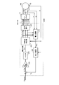
- FIG. 1 is an overall configuration diagram of an electric vehicle to which an electric motor control apparatus according to Embodiment 1 of the present invention is applied.
- electrically powered vehicle 100 includes a DC voltage generation unit 10 #, a smoothing capacitor C0, an inverter 14, an electric motor M1, a drive wheel DW, and a control device 30.
- DC voltage generation unit 10 # includes a power storage device B, system relays SR1 and SR2, a smoothing capacitor C1, and a converter 12.
- the power storage device B is typically configured by a secondary battery such as nickel metal hydride or lithium ion, an electric double layer capacitor, or the like.
- Voltage Vb of power storage device B and current Ib input / output to power storage device B are detected by voltage sensor 10 and current sensor 11, respectively.
- System relay SR1 is connected between the positive terminal of power storage device B and power line 6, and system relay SR2 is connected between the negative terminal of power storage device B and power line 5.
- System relays SR1 and SR2 are turned on / off by signal SE from control device 30.
- Converter 12 includes a reactor L1, power semiconductor switching elements Q1, Q2, and diodes D1, D2.
- Power semiconductor switching elements Q ⁇ b> 1 and Q ⁇ b> 2 are connected in series between power line 7 and power line 5. On / off of power semiconductor switching elements Q1, Q2 is controlled by control signals S1, S2 from control device 30.
- switching element As a power semiconductor switching element (hereinafter simply referred to as “switching element”), an IGBT (Insulated Gate Bipolar Transistor), a power MOS (Metal Oxide Semiconductor) transistor, a power bipolar transistor, or the like can be used. . Diodes D1 and D2 are connected in antiparallel to switching elements Q1 and Q2, respectively. Reactor L1 is connected between a connection node of switching elements Q1, Q2 and power line 6. Smoothing capacitor C 0 is connected between power line 7 and power line 5.
- IGBT Insulated Gate Bipolar Transistor
- MOS Metal Oxide Semiconductor
- the inverter 14 includes a U-phase upper and lower arm 15, a V-phase upper and lower arm 16, and a W-phase upper and lower arm 17 that are provided in parallel between the power line 7 and the power line 5.
- Each phase upper and lower arm is configured by a switching element connected in series between the power line 7 and the power line 5.
- the U-phase upper and lower arms 15 are composed of switching elements Q3 and Q4
- the V-phase upper and lower arms 16 are composed of switching elements Q5 and Q6
- the W-phase upper and lower arms 17 are composed of switching elements Q7 and Q8.
- Diodes D3 to D8 are connected in antiparallel to switching elements Q3 to Q8, respectively. Switching elements Q3 to Q8 are turned on / off by control signals S3 to S8 from control device 30.
- the motor M1 is typically a permanent magnet type three-phase AC synchronous motor, and is configured by connecting one end of three coils of U, V, and W phases to a neutral point. The other end of each phase coil is connected to the midpoint of the switching elements of each phase upper and lower arms 15-17. Electric motor M1 is driven by inverter 14 to generate torque for driving drive wheels DW.
- the electric motor M1 may be configured to have the function of a generator driven by the drive wheels DW when the vehicle is braked.
- the converter 12 is basically controlled so that the switching elements Q1, Q2 are turned on and off in a complementary manner within each switching period.
- converter 12 boosts voltage Vb supplied from power storage device B to voltage VH (this DC voltage corresponding to the input voltage to inverter 14 is also referred to as “system voltage” hereinafter).
- This boosting operation is performed by supplying electromagnetic energy accumulated in reactor L1 to switching line Q1 to power line 7 via switching element Q1 and diode D1.
- the converter 12 steps down the voltage VH to the voltage Vb during the step-down operation.
- This step-down operation is performed by supplying electromagnetic energy accumulated in reactor L1 to switching line Q1 to power line 6 via switching element Q2 and diode D2.
- the voltage conversion ratio (ratio of VH and Vb) in these step-up or step-down operations is controlled by the on-period ratio (duty ratio) of the switching elements Q1 and Q2 with respect to the switching period.
- Smoothing capacitor C0 smoothes the DC voltage from converter 12 and supplies the smoothed DC voltage to inverter 14.
- Voltage sensor 13 detects the voltage across smoothing capacitor C 0, that is, system voltage VH, and outputs the detected value to control device 30.
- the inverter 14 converts the DC voltage into the AC voltage by the switching operation of the switching elements Q3 to Q8 in response to the control signals S3 to S8 from the control device 30. And the electric motor M1 is driven so as to output a positive torque. Further, when the torque command value Trqcom of the electric motor M1 is zero, the inverter 14 converts the DC voltage into an AC voltage by switching operation in response to the control signals S3 to S8, and sets the electric motor M1 so that the torque becomes zero. To drive. Thereby, electric motor M1 is driven to generate zero or positive torque designated by torque command value Trqcom.
- the torque command value Trqcom of the electric motor M1 is set to be negative.
- the inverter 14 converts the AC voltage generated by the electric motor M1 into a DC voltage by the switching operation in response to the control signals S3 to S8, and supplies the converted DC voltage to the converter 12.
- regenerative braking here refers to braking that involves regenerative power generation when the driver operating the vehicle performs a footbrake operation, or regenerative power generation by turning off the accelerator pedal while driving, although the footbrake is not operated. Including decelerating (or stopping acceleration) the vehicle while moving.
- the current sensor 24 detects the motor current flowing through the electric motor M1 and outputs the detected value to the control device 30. Since the sum of instantaneous values of the three-phase currents iu, iv, iw is zero, the current sensor 24 is arranged to detect motor currents for two phases (eg, V-phase current iv and W-phase current iw). All you need is enough.
- the rotation angle sensor (resolver) 25 detects the rotation angle ⁇ of the rotor of the electric motor M1 and outputs the detected value to the control device 30.
- the control device 30 can calculate the rotation speed (number of rotations) and the angular speed ⁇ (rad / s) of the electric motor M1 based on the rotation angle ⁇ .
- the rotation angle sensor 25 may be omitted by directly calculating the rotation angle ⁇ from the motor voltage or current by the control device 30.
- the control device 30 is configured by an electronic control unit (ECU (Electronic Control Unit)), and is electrically operated by software processing by executing a program stored in advance by a CPU (not shown) and / or hardware processing by a dedicated electronic circuit. The operation of the vehicle 100 is controlled.
- ECU Electronic Control Unit
- the control device 30 includes a torque command value Trqcom, a voltage Vb detected by the voltage sensor 10, a current Ib detected by the current sensor 11, a system voltage VH detected by the voltage sensor 13, and a current sensor. Based on the motor currents iv, iw from 24, the rotation angle ⁇ from the rotation angle sensor 25, etc., the converter 12 and the inverter 14 so that the electric motor M1 outputs a torque according to the torque command value Trqcom by a control method described later. To control the operation. That is, control device 30 generates control signals S 1 to S 8 for controlling converter 12 and inverter 14 and outputs them to converter 12 and inverter 14.
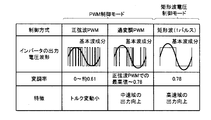
- FIG. 2 is a diagram illustrating a control mode of electric motor M1 shown in FIG. Referring to FIG. 2, in this electric vehicle 100, the PWM control mode and the rectangular wave voltage control mode are switched and used for control of electric motor M ⁇ b> 1, that is, power conversion in inverter 14.
- PWM control mode includes sinusoidal PWM control and overmodulation PWM control.
- sine wave PWM control on / off of the upper and lower arm elements of each phase is controlled in accordance with a voltage comparison between a sine wave voltage command and a carrier wave (typically a triangular wave).
- a carrier wave typically a triangular wave
- the fundamental wave component of the voltage applied to the motor M1 (hereinafter also simply referred to as “motor applied voltage”) is used. It can only be increased to about 0.61 times the input voltage.
- the ratio of the fundamental component (effective value) of the motor applied voltage (line voltage) to the input voltage of the inverter 14 (that is, the system voltage VH) is referred to as “modulation rate”.
- the overmodulation PWM control performs the same PWM control as the sine wave PWM control in a range where the amplitude of the voltage command (sine wave component) is larger than the carrier wave amplitude.
- the fundamental wave component can be increased by distorting the voltage command from the original sine wave waveform (amplitude correction), and the modulation rate can be increased from the maximum modulation rate in the sine wave PWM control to a range of 0.78. it can.
- the line voltage applied to the electric motor M1 is not a sine wave but a distorted voltage.
- one pulse of a rectangular wave whose ratio between the high level period and the low level period is 1: 1 is applied to the AC motor within the predetermined period.
- the modulation factor is increased to 0.78.
- the induced voltage increases as the rotational speed and output torque increase, so that the required drive voltage (motor required voltage) increases.
- the boosted voltage by the converter 12, that is, the system voltage VH needs to be set higher than the required motor voltage.
- the system voltage VH has a limit value (VH maximum voltage). Therefore, the PWM control mode by the sine wave PWM control or the overmodulation PWM control and the rectangular wave voltage control mode are selectively applied according to the operating state of the electric motor M1.
- the rectangular wave voltage control since the amplitude of the motor applied voltage is fixed, the rectangular wave voltage pulse phase control based on the torque deviation (the difference between the actual torque value (estimated value) and the torque command value) with respect to the torque command is performed. Torque control is executed.
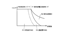
- FIG. 3 is a diagram for explaining the correspondence between the operating state of the AC motor and the control mode shown in FIG.
- sine wave PWM control is used to reduce the torque fluctuation
- overmodulation PWM control and high rotation speed range R3 are used in the low rotation speed range R1
- rectangular wave voltage control is applied in the middle rotation speed range R2
- application of overmodulation PWM control and rectangular wave voltage control can improve the output of AC electric motor M1.
- which one of the control modes shown in FIG. 2 is used is basically determined within the range of the realizable modulation rate.
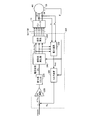
- FIG. 4 is a functional block diagram functionally illustrating the configuration of the control device 30 shown in FIG. Referring to FIG. 4, control device 30 includes a rectangular wave voltage control unit 200, a PWM control unit 400, and a control mode switching unit 490.
- Rectangular wave voltage control unit 200 receives torque command value Trqcom, motor currents iv, iw, and rotation angle ⁇ . Then, the rectangular wave voltage control unit 200 sets the phase of the voltage to be applied to the inverter 14 based on these signals by torque feedback control, and drives the inverter 14 based on the set voltage phase. Control signals S3 to S8 are generated and output to control mode switching section 490.
- PWM control unit 400 receives torque command value Trqcom, motor currents iv and iw detected by current sensor 24, and rotation angle ⁇ detected by rotation angle sensor 25. Based on these signals, PWM controller 400 generates voltage command values Vd # and Vq # to be applied to inverter 14 by current feedback control, and based on the generated voltage command values Vd # and Vq #. Then, control signals S3 to S8 for driving inverter 14 are generated and output to control mode switching unit 490. During overmodulation PWM control, the voltage amplitude is corrected and the fundamental wave component of the voltage command value is increased.
- Control mode switching unit 490 receives voltage command values Vd # and Vq # from PWM control unit 400, and receives system voltage VH from voltage sensor 13 (FIG. 1). Control mode switching unit 490 switches from the PWM control mode to the rectangular wave voltage control mode based on the modulation factor calculated from system voltage VH and voltage command values Vd # and Vq #. Specifically, control mode switching section 490 switches from PWM control mode to rectangular wave voltage control mode when the modulation factor reaches 0.78.
- Control mode switching unit 490 receives motor currents iv and iw and rotation angle ⁇ . Control mode switching unit 490 switches from the rectangular wave voltage control mode to the PWM control mode based on the current phase using these signals.
- FIG. 5 is a functional block diagram functionally illustrating the detailed configuration of the rectangular wave voltage control unit 200 shown in FIG.
- rectangular wave voltage control unit 200 includes power calculation unit 210, torque calculation unit 220, PI calculation unit 230, change rate limiter 235, rectangular wave generator 240, and signal generation unit 250. Including.
- the power calculation unit 210 calculates each phase current obtained from the V-phase current iv and the W-phase current iw detected by the current sensor 24 and each phase (U-phase, V-phase, W-phase) voltage command value Vu, Vv, Vw.
- the power (motor power) Pmt supplied to the motor M1 is calculated according to the following equation (1). At this time, filter processing for removing distortion components from the detected motor current (iv, iw) is also executed.
- the torque calculation unit 220 uses the motor power Pmt calculated by the power calculation unit 210 and the angular velocity ⁇ calculated from the rotation angle ⁇ of the electric motor M1 detected by the rotation angle sensor 25 to indicate torque that indicates actual torque.
- Estimated value Trq is calculated according to the following equation (2).
- Trq Pmt / ⁇ (2)
- voltage phase ⁇ v the phase of the rectangular wave voltage according to the control deviation.
- PI calculation unit 230 advances voltage phase ⁇ v when torque is insufficient, and delays voltage phase ⁇ v when torque is excessive.
- PI calculation unit 230 delays voltage phase ⁇ v when torque is insufficient, and advances voltage phase ⁇ v when torque is excessive.
- the change rate limiter 235 limits the change rate of the voltage phase ⁇ v. That is, in the rectangular wave voltage control, when the rotation speed of the electric motor M1 changes due to disturbance such as slip, the voltage phase ⁇ v is changed to maintain the torque. Specifically, when the rotation speed increases, the voltage phase ⁇ v is advanced to maintain the torque, and when the rotation speed decreases, the voltage phase ⁇ v is delayed. However, an offset occurs in the three-phase motor current accompanying the phase change of the voltage phase ⁇ v, and the offset amount increases as the change rate of the voltage phase ⁇ v increases. Since the stability of the rectangular wave voltage control is impaired when the current offset amount is increased, a change rate limiter 235 for limiting the change rate of the voltage phase ⁇ v is provided.
- the rectangular wave generator 240 generates each phase voltage command value (rectangular wave pulse) Vu, Vv, Vw according to the voltage phase ⁇ v.
- the signal generator 250 generates control signals S3 to S8 based on the phase voltage command values Vu, Vv, Vw. Then, when inverter 14 performs a switching operation according to control signals S3 to S8, a rectangular wave pulse according to voltage phase ⁇ v is applied as each phase voltage of the motor.
- a torque deviation ⁇ Trq may be obtained based on a detection value of the torque sensor by arranging a torque sensor instead of the power calculation unit 210 and the torque calculation unit 220.
- FIG. 6 is a functional block diagram functionally illustrating the detailed configuration of the PWM control unit 400 shown in FIG.
- PWM control unit 400 includes a current command generation unit 410, coordinate conversion units 420 and 450, a voltage command generation unit 440, and a PWM modulation unit 460.
- the current command generation unit 410 generates a d-axis current command value Idcom and a q-axis current command value Iqcom corresponding to the torque command value Trqcom of the electric motor M1 based on a map created in advance.
- the coordinate conversion unit 420 converts the v-phase current iv and the W-phase current iw detected by the current sensor 24 into the d-axis current Id and the q-axis by coordinate conversion (uvw3 phase ⁇ dq2 phase) using the rotation angle ⁇ of the electric motor M1. Convert to current Iq.
- the coordinate conversion unit 450 converts the d-axis voltage command value Vd # and the q-axis voltage command value Vq # into the U-phase, V-phase, and W-phase by coordinate conversion using the rotation angle ⁇ of the electric motor M1 (dq2 phase ⁇ uvw3 phase). Are converted into respective phase voltage command values Vu, Vv, Vw.
- the PWM modulation unit 460 generates control signals S3 to S8 for driving the inverter 14 based on the comparison between the phase voltage command values Vu, Vv, Vw and the carrier wave.
- the carrier wave is constituted by a triangular wave or a sawtooth wave having a predetermined frequency.
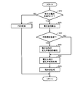
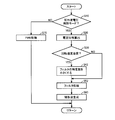
- FIG. 7 is a flowchart regarding the rate of change limiting process of the voltage phase ⁇ v executed by the control device 30 shown in FIG. The process of this flowchart is called from the main routine and executed every certain time or every time a predetermined condition is satisfied.
- control device 30 determines whether or not the control mode is a rectangular wave voltage control mode (step S10). When it is determined that the control mode is the rectangular wave voltage control mode (YES in step S10), control device 30 performs a PI operation on torque deviation ⁇ Trq with respect to torque command value Trqcom, thereby causing voltage phase ⁇ v of the rectangular wave voltage. Is calculated (step S20).
- the control device 30 determines whether or not the rotational speed of the electric motor M1 has suddenly changed (step S30).
- a threshold value indicating a sudden change in the rotation speed of the electric motor M1 is set in advance, and when the rate of change in the rotation speed exceeds the threshold value, it is determined that the rotation speed has changed suddenly.
- control device 30 relaxes the rate of change restriction on voltage phase ⁇ v (step S40). Specifically, the control device 30 sets an enlargement value larger than the normal value as the limit value of the change rate limiter 235 (FIG. 5). Note that the normal limit value of the change rate limiter 235 and the enlargement value are set in advance.
- step S40 is not executed and the process proceeds to step S50.
- control device 30 executes a change rate limiting process of the voltage phase ⁇ v by the change rate limiter 235 (step S50). Then, when the rate of change restriction process for voltage phase ⁇ v is executed, control device 30 generates phase voltage command values (rectangular wave pulses) Vu, Vv, Vw according to voltage phase ⁇ v (step S60).
- control device 30 executes the above-described PWM control (step S70).
- the change rate of the voltage phase ⁇ v of the rectangular wave voltage is limited by the change rate limiter 235 in the rectangular wave voltage control.
- the rate of change of the rotational speed is larger than a predetermined value indicating a sudden change in the rotational speed of the electric motor M1
- the restriction on the rate of change of the voltage phase ⁇ v is relaxed.
- the control stability and the torque response can be made compatible for the rectangular wave voltage control of the electric motor M1.
- the change rate limiter 235 is used as the change rate limiting unit for limiting the change rate of the voltage phase ⁇ v.
- the filter is used as the change rate limiting unit, and the time constant of the filter is changed. May change (relax) the rate of change of the voltage phase ⁇ v.
- FIG. 8 is a functional block diagram functionally illustrating the configuration of the rectangular wave voltage control unit in this modification.
- rectangular wave voltage control unit 200 ⁇ / b> A includes a filter 236 instead of change rate limiter 235 in the configuration of rectangular wave voltage control unit 200 in the first embodiment shown in FIG. 5.
- the filter 236 is provided to limit the rate of change of the voltage phase ⁇ v, and is constituted by a low-pass filter having a variable time constant, for example.
- the filtering function by the filter 236 is relaxed by reducing the time constant of the filter 236, and the restriction on the rate of change of the voltage phase ⁇ v is relaxed.
- the other configuration of the rectangular wave voltage control unit 200A is the same as that of the rectangular wave voltage control unit 200 shown in FIG.
- FIG. 9 is a flowchart related to the change rate limiting process of the voltage phase ⁇ v executed by the control device 30 in this modification. The processing of this flowchart is also called from the main routine and executed every certain time or every time a predetermined condition is satisfied.
- this flowchart includes steps S42 and S52 in place of steps S40 and S50 in the flowchart shown in FIG. That is, when it is determined in step S30 that the rotation speed of electric motor M1 has suddenly changed (YES in step S30), control device 30 makes the time constant of filter 236 (FIG. 8) smaller than normal (step S42). . The normal time constant of the filter 236 and the change value are set in advance. On the other hand, when it is determined in step S30 that the rotation speed has not changed suddenly (NO in step S30), step S42 is not executed and the process proceeds to step S52.
- control device 30 performs the filter process of the voltage phase ⁇ v by the filter 236 (step S52). Thereby, the rate of change of voltage phase ⁇ v is limited. Then, when the filter process of voltage phase ⁇ v is executed, the process proceeds to step S60, and phase voltage command values (rectangular wave pulses) Vu, Vv, Vw are generated according to voltage phase ⁇ v.
- the rate of change in the voltage phase ⁇ v is increased only on the side that advances the voltage phase ⁇ v.
- the restriction on the rate of change of the voltage phase ⁇ v is relaxed only on the side that delays the voltage phase ⁇ v. This eliminates unnecessary relaxation of the rate of change restriction and ensures control stability.
- the overall configuration of the electric vehicle 100 and the control device 30 in the second embodiment is the same as that in the first embodiment.
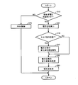
- FIG. 10 is a flowchart relating to the rate of change limiting process of the voltage phase ⁇ v executed by the control device 30 according to the second embodiment. The processing of this flowchart is also called from the main routine and executed every certain time or every time a predetermined condition is satisfied.
- this flowchart includes steps S44, S46, and S48 in place of step S40 in the flowchart shown in FIG. That is, when it is determined in step S30 that the rotation speed of electric motor M1 has suddenly changed (YES in step S30), control device 30 determines whether or not the change in rotation speed is in the acceleration direction (step S44). If it is determined that the change in rotational speed is in the speed increasing direction (YES in step S44), control device 30 relaxes the rate of change in voltage phase ⁇ v only on the side that advances voltage phase ⁇ v (step S46). That is, on the side where the voltage phase ⁇ v is delayed, the restriction on the rate of change of the voltage phase ⁇ v is not relaxed.
- control device 30 relaxes the rate of change in voltage phase ⁇ v only on the side that delays voltage phase ⁇ v (step S44). S48). That is, on the side where the voltage phase ⁇ v is advanced, the change rate limitation of the voltage phase ⁇ v is not relaxed.
- step S46 or step S48 the process proceeds to step S50, and the change rate limiting process of the voltage phase ⁇ v is executed.
- the rate of change of the voltage phase ⁇ v is limited by the rate-of-change limiter 235
- the case where the rate of change of the voltage phase ⁇ v is limited by the filter 236 (implementation) The same can be applied to the modified example of the first embodiment. That is, the time constant of the filter 236 can be set separately for the side that advances the voltage phase ⁇ v and the side that delays it, and when the change in rotational speed is in the acceleration direction, the time constant only for the side that advances the voltage phase ⁇ v is normally set. When the rotation speed changes in the deceleration direction, the time constant only on the side of delaying the voltage phase ⁇ v may be reduced.
- the second embodiment when the change in the rotational speed is in the speed increasing direction, only the voltage phase ⁇ v is advanced. On the other hand, when the change in the rotational speed is in the deceleration direction, the voltage phase ⁇ v is set. Since the restriction on the change rate of the voltage phase ⁇ v is relaxed only on the delay side, the relaxation of the change rate restriction can be minimized. Therefore, according to the second embodiment, the stability of the rectangular wave voltage control can be improved as compared with the first embodiment.
- the overall configuration of the electric vehicle 100 and the control device 30 in the third embodiment is the same as that in the first embodiment.
- FIG. 11 is a flowchart related to the change rate limiting process of the voltage phase ⁇ v executed by the control device 30 in the third embodiment. The processing of this flowchart is also called from the main routine and executed every certain time or every time a predetermined condition is satisfied.
- this flowchart includes step S32 instead of step S30 in the flowchart shown in FIG. That is, when voltage phase ⁇ v of the rectangular wave voltage is calculated in step S20, control device 30 determines whether or not the torque command of electric motor M1 has suddenly changed (step S32).
- a threshold value indicating a sudden change in the torque command value Trqcom of the electric motor M1 is set in advance, and when the rate of change of the torque command value Trqcom exceeds the threshold value, it is determined that the torque command has changed suddenly.
- step S32 If it is determined that the torque command of electric motor M1 has suddenly changed (YES in step S32), the process proceeds to step S40, and the rate of change restriction on voltage phase ⁇ v is relaxed. On the other hand, when it is determined in step S32 that the torque command has not changed suddenly (NO in step S32), step S40 is not executed and the process proceeds to step S50.
- the restriction on the rate of change of the voltage phase ⁇ v is relaxed when the rotational speed or torque command of the electric motor M1 changes suddenly. You may do it.
- both control stability and torque response can be achieved for the rectangular wave voltage control of the electric motor M1.
- the slip and grip of the drive wheel DW are detected based on the detected value of the rotation speed (rotation number) of the drive wheel DW and the rotation angle ⁇ of the motor M1, and the rotation speed of the motor M1 is determined. You may determine whether it changed suddenly by whether the slip of the driving wheel DW or the grip after a slip generate
- the present invention can be applied to various vehicles having the basic configuration of the electric vehicle 100 shown in FIG.
- the present invention is also applicable to a hybrid vehicle in which an engine is further mounted in the configuration shown in FIG.
- PI calculation unit 230 corresponds to an example of “voltage command generation unit” in the present invention
- each of change rate limiter 235 and filter 236 is one of “change rate limiting unit” in the present invention. This corresponds to the embodiment.
Landscapes
- Engineering & Computer Science (AREA)
- Power Engineering (AREA)
- Transportation (AREA)
- Mechanical Engineering (AREA)
- Life Sciences & Earth Sciences (AREA)
- Sustainable Development (AREA)
- Sustainable Energy (AREA)
- Control Of Ac Motors In General (AREA)
- Electric Propulsion And Braking For Vehicles (AREA)
- Control Of Motors That Do Not Use Commutators (AREA)
Abstract
Priority Applications (5)
| Application Number | Priority Date | Filing Date | Title |
|---|---|---|---|
| EP11863078.9A EP2696498B1 (fr) | 2011-04-05 | 2011-04-05 | Appareil de commande pour moteur électrique, véhicule électrique équipé de ce moteur et procédé de commande du moteur électrique |
| US14/008,117 US9020731B2 (en) | 2011-04-05 | 2011-04-05 | Control apparatus for electric motor, electrically-powered vehicle including the control apparatus, and method for controlling electric motor |
| CN201180069868.1A CN103444074B (zh) | 2011-04-05 | 2011-04-05 | 电动机的控制装置及具备该电动机的控制装置的电动车辆、以及电动机的控制方法 |
| JP2013508661A JP5633639B2 (ja) | 2011-04-05 | 2011-04-05 | 電動機の制御装置およびそれを備える電動車両、ならびに電動機の制御方法 |
| PCT/JP2011/058598 WO2012137300A1 (fr) | 2011-04-05 | 2011-04-05 | Appareil de commande pour moteur électrique, véhicule électrique équipé de ce moteur et procédé de commande du moteur électrique |
Applications Claiming Priority (1)
| Application Number | Priority Date | Filing Date | Title |
|---|---|---|---|
| PCT/JP2011/058598 WO2012137300A1 (fr) | 2011-04-05 | 2011-04-05 | Appareil de commande pour moteur électrique, véhicule électrique équipé de ce moteur et procédé de commande du moteur électrique |
Publications (1)
| Publication Number | Publication Date |
|---|---|
| WO2012137300A1 true WO2012137300A1 (fr) | 2012-10-11 |
Family
ID=46968741
Family Applications (1)
| Application Number | Title | Priority Date | Filing Date |
|---|---|---|---|
| PCT/JP2011/058598 Ceased WO2012137300A1 (fr) | 2011-04-05 | 2011-04-05 | Appareil de commande pour moteur électrique, véhicule électrique équipé de ce moteur et procédé de commande du moteur électrique |
Country Status (5)
| Country | Link |
|---|---|
| US (1) | US9020731B2 (fr) |
| EP (1) | EP2696498B1 (fr) |
| JP (1) | JP5633639B2 (fr) |
| CN (1) | CN103444074B (fr) |
| WO (1) | WO2012137300A1 (fr) |
Cited By (2)
| Publication number | Priority date | Publication date | Assignee | Title |
|---|---|---|---|---|
| JP2017532946A (ja) * | 2014-10-27 | 2017-11-02 | ヴァレオ エキプマン エレクトリク モトゥール | 多相同期回転電気機器を制御するための方法および装置、ならびに対応する自動車用の可逆的電気機器 |
| WO2024053181A1 (fr) * | 2022-09-08 | 2024-03-14 | 日立Astemo株式会社 | Dispositif de commande de moteur à courant alternatif, véhicule électrique et procédé de commande de moteur à courant alternatif |
Families Citing this family (15)
| Publication number | Priority date | Publication date | Assignee | Title |
|---|---|---|---|---|
| US9000701B2 (en) * | 2011-12-30 | 2015-04-07 | GM Global Technology Operations LLC | Methods, systems and apparatus for generating voltage commands used to control operation of a permanent magnet machine |
| US10254374B2 (en) * | 2013-07-16 | 2019-04-09 | Ford Global Technologies, Llc | Method of current sensor related torque error estimation for IPMSM e-drive system |
| JP6282487B2 (ja) * | 2014-02-25 | 2018-02-21 | 三菱重工業株式会社 | 過給機及び船舶 |
| CN105811827A (zh) * | 2014-12-29 | 2016-07-27 | 上海大郡动力控制技术有限公司 | 纯电动汽车转速波动的抑制方法 |
| US10656026B2 (en) | 2016-04-15 | 2020-05-19 | Emerson Climate Technologies, Inc. | Temperature sensing circuit for transmitting data across isolation barrier |
| US10305373B2 (en) | 2016-04-15 | 2019-05-28 | Emerson Climate Technologies, Inc. | Input reference signal generation systems and methods |
| US10277115B2 (en) | 2016-04-15 | 2019-04-30 | Emerson Climate Technologies, Inc. | Filtering systems and methods for voltage control |
| US9933842B2 (en) | 2016-04-15 | 2018-04-03 | Emerson Climate Technologies, Inc. | Microcontroller architecture for power factor correction converter |
| US10284132B2 (en) | 2016-04-15 | 2019-05-07 | Emerson Climate Technologies, Inc. | Driver for high-frequency switching voltage converters |
| US10763740B2 (en) | 2016-04-15 | 2020-09-01 | Emerson Climate Technologies, Inc. | Switch off time control systems and methods |
| US10312798B2 (en) | 2016-04-15 | 2019-06-04 | Emerson Electric Co. | Power factor correction circuits and methods including partial power factor correction operation for boost and buck power converters |
| JP7121248B2 (ja) * | 2017-09-14 | 2022-08-18 | シンフォニアテクノロジー株式会社 | 同期電動機の制御装置及び制御方法 |
| CN108809170B (zh) * | 2018-06-11 | 2021-01-29 | 北京北方华创微电子装备有限公司 | 一种匹配器电机自动控制电路 |
| CN111216564B (zh) * | 2018-11-27 | 2022-05-24 | 宇通客车股份有限公司 | 一种车辆扭矩控制方法及装置 |
| WO2022118822A1 (fr) * | 2020-12-04 | 2022-06-09 | 株式会社日立製作所 | Dispositif d'entraînement et procédé d'entraînement pour machine électrique rotative, et véhicule ferroviaire |
Citations (6)
| Publication number | Priority date | Publication date | Assignee | Title |
|---|---|---|---|---|
| JPH09312978A (ja) * | 1996-05-21 | 1997-12-02 | Toyo Electric Mfg Co Ltd | 直流−交流電流形変換器の制御装置 |
| JP2000050689A (ja) | 1998-07-24 | 2000-02-18 | Toyota Motor Corp | 交流電動機の駆動制御装置 |
| JP2005045880A (ja) * | 2003-07-24 | 2005-02-17 | Toyota Motor Corp | 負荷駆動装置および負荷駆動装置における電圧変換の制御をコンピュータに実行させるためのプログラムを記録したコンピュータ読取り可能な記録媒体 |
| JP2005051850A (ja) | 2003-07-30 | 2005-02-24 | Toyota Motor Corp | 車両および車両の制御方法 |
| JP2006232492A (ja) * | 2005-02-25 | 2006-09-07 | Mitsubishi Heavy Ind Ltd | フォークリフト及び、それに適用される誘導モータ制御方法 |
| JP2008167557A (ja) | 2006-12-27 | 2008-07-17 | Nissan Motor Co Ltd | モータ制御方法 |
Family Cites Families (11)
| Publication number | Priority date | Publication date | Assignee | Title |
|---|---|---|---|---|
| US4608527A (en) * | 1982-12-20 | 1986-08-26 | Sundstrand Corporation | Phase advance waveform generator for brushless DC actuator system controller |
| IN172484B (fr) * | 1990-09-10 | 1993-08-28 | Paramount Sinters Private Limi | |
| JP4092811B2 (ja) * | 1999-04-19 | 2008-05-28 | トヨタ自動車株式会社 | モータ制御装置および制御方法 |
| JP4175207B2 (ja) * | 2003-07-30 | 2008-11-05 | トヨタ自動車株式会社 | 車両および車両の制御方法 |
| JP4706324B2 (ja) * | 2005-05-10 | 2011-06-22 | トヨタ自動車株式会社 | モータ駆動システムの制御装置 |
| JP5149695B2 (ja) * | 2008-05-15 | 2013-02-20 | パナソニック株式会社 | モータ駆動制御装置 |
| JP5407322B2 (ja) * | 2008-12-22 | 2014-02-05 | トヨタ自動車株式会社 | 交流電動機の制御システム |
| WO2010150786A1 (fr) * | 2009-06-22 | 2010-12-29 | アイシン・エィ・ダブリュ株式会社 | Dispositif de commande pour unité d'entraînement à moteur électrique |
| US8508166B2 (en) * | 2009-08-10 | 2013-08-13 | Emerson Climate Technologies, Inc. | Power factor correction with variable bus voltage |
| JP5120669B2 (ja) * | 2010-03-31 | 2013-01-16 | アイシン・エィ・ダブリュ株式会社 | 電動機駆動装置の制御装置 |
| US8766588B2 (en) * | 2011-03-30 | 2014-07-01 | Bose Corporation | Rate limited common mode control for pulse-width modulation drives |
-
2011
- 2011-04-05 US US14/008,117 patent/US9020731B2/en active Active
- 2011-04-05 EP EP11863078.9A patent/EP2696498B1/fr active Active
- 2011-04-05 JP JP2013508661A patent/JP5633639B2/ja active Active
- 2011-04-05 CN CN201180069868.1A patent/CN103444074B/zh active Active
- 2011-04-05 WO PCT/JP2011/058598 patent/WO2012137300A1/fr not_active Ceased
Patent Citations (6)
| Publication number | Priority date | Publication date | Assignee | Title |
|---|---|---|---|---|
| JPH09312978A (ja) * | 1996-05-21 | 1997-12-02 | Toyo Electric Mfg Co Ltd | 直流−交流電流形変換器の制御装置 |
| JP2000050689A (ja) | 1998-07-24 | 2000-02-18 | Toyota Motor Corp | 交流電動機の駆動制御装置 |
| JP2005045880A (ja) * | 2003-07-24 | 2005-02-17 | Toyota Motor Corp | 負荷駆動装置および負荷駆動装置における電圧変換の制御をコンピュータに実行させるためのプログラムを記録したコンピュータ読取り可能な記録媒体 |
| JP2005051850A (ja) | 2003-07-30 | 2005-02-24 | Toyota Motor Corp | 車両および車両の制御方法 |
| JP2006232492A (ja) * | 2005-02-25 | 2006-09-07 | Mitsubishi Heavy Ind Ltd | フォークリフト及び、それに適用される誘導モータ制御方法 |
| JP2008167557A (ja) | 2006-12-27 | 2008-07-17 | Nissan Motor Co Ltd | モータ制御方法 |
Non-Patent Citations (1)
| Title |
|---|
| See also references of EP2696498A4 * |
Cited By (3)
| Publication number | Priority date | Publication date | Assignee | Title |
|---|---|---|---|---|
| JP2017532946A (ja) * | 2014-10-27 | 2017-11-02 | ヴァレオ エキプマン エレクトリク モトゥール | 多相同期回転電気機器を制御するための方法および装置、ならびに対応する自動車用の可逆的電気機器 |
| WO2024053181A1 (fr) * | 2022-09-08 | 2024-03-14 | 日立Astemo株式会社 | Dispositif de commande de moteur à courant alternatif, véhicule électrique et procédé de commande de moteur à courant alternatif |
| JP2024038588A (ja) * | 2022-09-08 | 2024-03-21 | 日立Astemo株式会社 | 交流モータ制御装置および電気車、交流モータの制御方法 |
Also Published As
| Publication number | Publication date |
|---|---|
| EP2696498A4 (fr) | 2016-01-06 |
| JP5633639B2 (ja) | 2014-12-03 |
| US9020731B2 (en) | 2015-04-28 |
| JPWO2012137300A1 (ja) | 2014-07-28 |
| EP2696498A1 (fr) | 2014-02-12 |
| CN103444074A (zh) | 2013-12-11 |
| CN103444074B (zh) | 2015-12-16 |
| EP2696498B1 (fr) | 2017-02-01 |
| US20140018991A1 (en) | 2014-01-16 |
Similar Documents
| Publication | Publication Date | Title |
|---|---|---|
| JP5633639B2 (ja) | 電動機の制御装置およびそれを備える電動車両、ならびに電動機の制御方法 | |
| CN102282758B (zh) | 交流电动机的控制装置及电动车辆 | |
| JP5133834B2 (ja) | 交流電動機の制御装置 | |
| EP2733844B1 (fr) | Véhicule et procédé permettant de contrôler un véhicule | |
| JP4604820B2 (ja) | モータ駆動システムの制御装置 | |
| JP5482574B2 (ja) | 交流電動機の制御システム | |
| JP2006320039A (ja) | モータ駆動システムの制御装置 | |
| JP5369630B2 (ja) | 交流電動機の制御装置 | |
| JP2006311768A (ja) | モータ駆動システムの制御装置 | |
| JP5281370B2 (ja) | 交流電動機の制御装置 | |
| CN103904982A (zh) | 车辆和用于车辆的控制装置 | |
| CN103904980B (zh) | 车辆和用于车辆的控制装置 | |
| JP2011067010A (ja) | 車両のモータ駆動装置 | |
| JP5696607B2 (ja) | 交流電動機の制御装置および制御方法 | |
| JP2010166707A (ja) | 交流電動機の制御装置 | |
| JP5780022B2 (ja) | 交流電動機の制御装置および制御方法 | |
| JP5884297B2 (ja) | モータ駆動制御システムおよびそれを搭載する車両、ならびにモータ駆動制御システムの制御方法 | |
| JP5768542B2 (ja) | 交流電動機の制御装置および制御方法 | |
| JP2010226780A (ja) | 交流電動機の制御システム |
Legal Events
| Date | Code | Title | Description |
|---|---|---|---|
| 121 | Ep: the epo has been informed by wipo that ep was designated in this application |
Ref document number: 11863078 Country of ref document: EP Kind code of ref document: A1 |
|
| ENP | Entry into the national phase |
Ref document number: 2013508661 Country of ref document: JP Kind code of ref document: A |
|
| WWE | Wipo information: entry into national phase |
Ref document number: 14008117 Country of ref document: US |
|
| NENP | Non-entry into the national phase |
Ref country code: DE |
|
| REEP | Request for entry into the european phase |
Ref document number: 2011863078 Country of ref document: EP |
|
| WWE | Wipo information: entry into national phase |
Ref document number: 2011863078 Country of ref document: EP |