WO2012137329A1 - ハイブリッド車両およびその制御方法 - Google Patents
ハイブリッド車両およびその制御方法 Download PDFInfo
- Publication number
- WO2012137329A1 WO2012137329A1 PCT/JP2011/058775 JP2011058775W WO2012137329A1 WO 2012137329 A1 WO2012137329 A1 WO 2012137329A1 JP 2011058775 W JP2011058775 W JP 2011058775W WO 2012137329 A1 WO2012137329 A1 WO 2012137329A1
- Authority
- WO
- WIPO (PCT)
- Prior art keywords
- internal combustion
- stopped
- combustion engine
- threshold value
- vehicle
- Prior art date
- Legal status (The legal status is an assumption and is not a legal conclusion. Google has not performed a legal analysis and makes no representation as to the accuracy of the status listed.)
- Ceased
Links
Images




Classifications
-
- B—PERFORMING OPERATIONS; TRANSPORTING
- B60—VEHICLES IN GENERAL
- B60W—CONJOINT CONTROL OF VEHICLE SUB-UNITS OF DIFFERENT TYPE OR DIFFERENT FUNCTION; CONTROL SYSTEMS SPECIALLY ADAPTED FOR HYBRID VEHICLES; ROAD VEHICLE DRIVE CONTROL SYSTEMS FOR PURPOSES NOT RELATED TO THE CONTROL OF A PARTICULAR SUB-UNIT
- B60W20/00—Control systems specially adapted for hybrid vehicles
- B60W20/40—Controlling the engagement or disengagement of prime movers, e.g. for transition between prime movers
-
- B—PERFORMING OPERATIONS; TRANSPORTING
- B60—VEHICLES IN GENERAL
- B60K—ARRANGEMENT OR MOUNTING OF PROPULSION UNITS OR OF TRANSMISSIONS IN VEHICLES; ARRANGEMENT OR MOUNTING OF PLURAL DIVERSE PRIME-MOVERS IN VEHICLES; AUXILIARY DRIVES FOR VEHICLES; INSTRUMENTATION OR DASHBOARDS FOR VEHICLES; ARRANGEMENTS IN CONNECTION WITH COOLING, AIR INTAKE, GAS EXHAUST OR FUEL SUPPLY OF PROPULSION UNITS IN VEHICLES
- B60K6/00—Arrangement or mounting of plural diverse prime-movers for mutual or common propulsion, e.g. hybrid propulsion systems comprising electric motors and internal combustion engines
- B60K6/20—Arrangement or mounting of plural diverse prime-movers for mutual or common propulsion, e.g. hybrid propulsion systems comprising electric motors and internal combustion engines the prime-movers consisting of electric motors and internal combustion engines, e.g. HEVs
- B60K6/42—Arrangement or mounting of plural diverse prime-movers for mutual or common propulsion, e.g. hybrid propulsion systems comprising electric motors and internal combustion engines the prime-movers consisting of electric motors and internal combustion engines, e.g. HEVs characterised by the architecture of the hybrid electric vehicle
- B60K6/44—Series-parallel type
- B60K6/445—Differential gearing distribution type
-
- B—PERFORMING OPERATIONS; TRANSPORTING
- B60—VEHICLES IN GENERAL
- B60W—CONJOINT CONTROL OF VEHICLE SUB-UNITS OF DIFFERENT TYPE OR DIFFERENT FUNCTION; CONTROL SYSTEMS SPECIALLY ADAPTED FOR HYBRID VEHICLES; ROAD VEHICLE DRIVE CONTROL SYSTEMS FOR PURPOSES NOT RELATED TO THE CONTROL OF A PARTICULAR SUB-UNIT
- B60W10/00—Conjoint control of vehicle sub-units of different type or different function
- B60W10/04—Conjoint control of vehicle sub-units of different type or different function including control of propulsion units
- B60W10/06—Conjoint control of vehicle sub-units of different type or different function including control of propulsion units including control of combustion engines
-
- B—PERFORMING OPERATIONS; TRANSPORTING
- B60—VEHICLES IN GENERAL
- B60W—CONJOINT CONTROL OF VEHICLE SUB-UNITS OF DIFFERENT TYPE OR DIFFERENT FUNCTION; CONTROL SYSTEMS SPECIALLY ADAPTED FOR HYBRID VEHICLES; ROAD VEHICLE DRIVE CONTROL SYSTEMS FOR PURPOSES NOT RELATED TO THE CONTROL OF A PARTICULAR SUB-UNIT
- B60W20/00—Control systems specially adapted for hybrid vehicles
-
- B—PERFORMING OPERATIONS; TRANSPORTING
- B60—VEHICLES IN GENERAL
- B60W—CONJOINT CONTROL OF VEHICLE SUB-UNITS OF DIFFERENT TYPE OR DIFFERENT FUNCTION; CONTROL SYSTEMS SPECIALLY ADAPTED FOR HYBRID VEHICLES; ROAD VEHICLE DRIVE CONTROL SYSTEMS FOR PURPOSES NOT RELATED TO THE CONTROL OF A PARTICULAR SUB-UNIT
- B60W20/00—Control systems specially adapted for hybrid vehicles
- B60W20/10—Controlling the power contribution of each of the prime movers to meet required power demand
- B60W20/13—Controlling the power contribution of each of the prime movers to meet required power demand in order to stay within battery power input or output limits; in order to prevent overcharging or battery depletion
-
- B—PERFORMING OPERATIONS; TRANSPORTING
- B60—VEHICLES IN GENERAL
- B60W—CONJOINT CONTROL OF VEHICLE SUB-UNITS OF DIFFERENT TYPE OR DIFFERENT FUNCTION; CONTROL SYSTEMS SPECIALLY ADAPTED FOR HYBRID VEHICLES; ROAD VEHICLE DRIVE CONTROL SYSTEMS FOR PURPOSES NOT RELATED TO THE CONTROL OF A PARTICULAR SUB-UNIT
- B60W50/00—Details of control systems for road vehicle drive control not related to the control of a particular sub-unit, e.g. process diagnostic or vehicle driver interfaces
- B60W2050/0062—Adapting control system settings
-
- B—PERFORMING OPERATIONS; TRANSPORTING
- B60—VEHICLES IN GENERAL
- B60W—CONJOINT CONTROL OF VEHICLE SUB-UNITS OF DIFFERENT TYPE OR DIFFERENT FUNCTION; CONTROL SYSTEMS SPECIALLY ADAPTED FOR HYBRID VEHICLES; ROAD VEHICLE DRIVE CONTROL SYSTEMS FOR PURPOSES NOT RELATED TO THE CONTROL OF A PARTICULAR SUB-UNIT
- B60W2510/00—Input parameters relating to a particular sub-units
- B60W2510/24—Energy storage means
- B60W2510/242—Energy storage means for electrical energy
- B60W2510/244—Charge state
-
- B—PERFORMING OPERATIONS; TRANSPORTING
- B60—VEHICLES IN GENERAL
- B60W—CONJOINT CONTROL OF VEHICLE SUB-UNITS OF DIFFERENT TYPE OR DIFFERENT FUNCTION; CONTROL SYSTEMS SPECIALLY ADAPTED FOR HYBRID VEHICLES; ROAD VEHICLE DRIVE CONTROL SYSTEMS FOR PURPOSES NOT RELATED TO THE CONTROL OF A PARTICULAR SUB-UNIT
- B60W2540/00—Input parameters relating to occupants
- B60W2540/16—Ratio selector position
-
- Y—GENERAL TAGGING OF NEW TECHNOLOGICAL DEVELOPMENTS; GENERAL TAGGING OF CROSS-SECTIONAL TECHNOLOGIES SPANNING OVER SEVERAL SECTIONS OF THE IPC; TECHNICAL SUBJECTS COVERED BY FORMER USPC CROSS-REFERENCE ART COLLECTIONS [XRACs] AND DIGESTS
- Y02—TECHNOLOGIES OR APPLICATIONS FOR MITIGATION OR ADAPTATION AGAINST CLIMATE CHANGE
- Y02T—CLIMATE CHANGE MITIGATION TECHNOLOGIES RELATED TO TRANSPORTATION
- Y02T10/00—Road transport of goods or passengers
- Y02T10/60—Other road transportation technologies with climate change mitigation effect
- Y02T10/62—Hybrid vehicles
-
- Y—GENERAL TAGGING OF NEW TECHNOLOGICAL DEVELOPMENTS; GENERAL TAGGING OF CROSS-SECTIONAL TECHNOLOGIES SPANNING OVER SEVERAL SECTIONS OF THE IPC; TECHNICAL SUBJECTS COVERED BY FORMER USPC CROSS-REFERENCE ART COLLECTIONS [XRACs] AND DIGESTS
- Y10—TECHNICAL SUBJECTS COVERED BY FORMER USPC
- Y10S—TECHNICAL SUBJECTS COVERED BY FORMER USPC CROSS-REFERENCE ART COLLECTIONS [XRACs] AND DIGESTS
- Y10S903/00—Hybrid electric vehicles, HEVS
- Y10S903/902—Prime movers comprising electrical and internal combustion motors
- Y10S903/903—Prime movers comprising electrical and internal combustion motors having energy storing means, e.g. battery, capacitor
Definitions
- the present invention relates to a hybrid vehicle and a control method therefor, and more particularly, to a hybrid vehicle equipped with an internal combustion engine, a power storage device, and a traveling motor, and a control method therefor.
- Patent Document 1 discloses an engine stop / start control device applicable to such a hybrid vehicle.
- This engine stop / start control device is employed in a vehicle that stops an engine when a predetermined stop condition is satisfied and starts the engine when a predetermined start condition is satisfied. Then, the engine stop / start control device changes the start condition to the side on which the engine is difficult to start when compared with the non-travel position when the shift position is the travel position and the means for detecting the shift position of the vehicle. Means.
- the power generation device uses the internal combustion engine to charge the power storage device.
- the remaining capacity of the power storage device hereinafter also referred to as “SOC”, for example, expressed as a percentage of the fully charged state
- SOC the remaining capacity of the power storage device
- the internal combustion engine is operated to charge the power storage device. This charging is executed even when the vehicle is stopped if the state of charge of the power storage device decreases.
- the operation of the stopped internal combustion engine can cause discomfort to the user in a hybrid vehicle.
- charging while stopped is not efficient. That is, in general, an internal combustion engine operates more efficiently in a state where the output is somewhat high.
- the charging while the vehicle is stopped is not efficient because it is sufficient to operate the internal combustion engine in a low output state. Therefore, when it is desired to suppress the operation of the internal combustion engine while the vehicle is stopped while realizing recovery when the charged state of the power storage device is lowered, the above publication discloses that the internal combustion engine is stopped and started under any conditions from the viewpoint of the charged state. There is no specific study on what to do.
- the present invention has been made to solve such a problem, and the object of the present invention is to achieve recovery of the charged state in the hybrid vehicle when the charged state of the power storage device is lowered, while the vehicle is stopped. It is to suppress user discomfort due to the operation of the internal combustion engine.
- the hybrid vehicle includes a power storage device, an internal combustion engine, at least one electric motor, a control device, and a shift selection device.
- At least one electric motor has a power generation function for supplying electric power to the power storage device by being driven by the internal combustion engine, and a function for generating a traveling driving force.
- the control device controls the start and stop of the internal combustion engine based on the start condition and stop condition of the internal combustion engine set from physical quantities related to the state of charge of the power storage device.
- the shift selection device is for selecting one of a plurality of shift ranges included in either the travel range or the non-travel range.
- the control device sets the start condition and the stop condition of the internal combustion engine so that the operation continuation time of the internal combustion engine decreases compared to when traveling, and the non-travel range is If selected, the stop condition of the internal combustion engine is set such that the operation duration time of the internal combustion engine increases as compared with the case where the travel range is selected when the vehicle is stopped.
- the control device changes the stop condition of the internal combustion engine so that the operation duration time of the internal combustion engine decreases compared to when traveling, and the non-travel range is selected. If so, the change of the stop condition of the internal combustion engine is stopped.
- the physical quantity is a remaining capacity of the power storage device.
- the control device starts the internal combustion engine when the remaining capacity falls below the first threshold value corresponding to the start condition of the internal combustion engine, and when the travel range is selected when the vehicle is stopped, the stop condition of the internal combustion engine.
- the remaining capacity exceeds a second threshold value that is greater than the first threshold value
- the internal combustion engine is stopped, and when the non-traveling range is selected, the second threshold value is exceeded. If the remaining capacity exceeds a larger third threshold value, the internal combustion engine is stopped.
- the control device stops the internal combustion engine while the vehicle is stopped when the remaining capacity exceeds the second threshold value, and the internal combustion engine when the travel starts.
- the eco-run mode setting is canceled.
- the physical quantity is a voltage of a power storage device. Then, the control device starts the internal combustion engine when the voltage falls below the first threshold value corresponding to the start condition of the internal combustion engine, and when the travel range is selected when the vehicle is stopped, the control device sets the stop condition of the internal combustion engine. If the voltage exceeds a corresponding second threshold value that is greater than the first threshold value, the internal combustion engine is stopped, and if a non-traveling range is selected, it is greater than the second threshold value. When the voltage exceeds the third threshold, the internal combustion engine is stopped.
- the physical quantity includes an elapsed time since the charging of the power storage device is started. Then, after the internal combustion engine is started based on the start condition of the internal combustion engine, the control device sets the first threshold time corresponding to the stop condition of the internal combustion engine to the elapsed time when the travel range is selected when the vehicle stops. When the non-traveling range is selected, the internal combustion engine is stopped when the elapsed time exceeds a second threshold time longer than the first threshold time.
- the control method is a hybrid vehicle control method.
- the hybrid vehicle includes a power storage device, an internal combustion engine, at least one electric motor, and a shift selection device.
- At least one electric motor has a power generation function for supplying electric power to the power storage device by being driven by the internal combustion engine, and a function for generating a traveling driving force.
- the shift selection device is for selecting one of a plurality of shift ranges included in either the travel range or the non-travel range.
- the control method includes a step of controlling start and stop of the internal combustion engine based on a start condition and a stop condition of the internal combustion engine set from a physical quantity related to a charging state of the power storage device, and a travel range when the vehicle is stopped.
- the traveling range is Setting the stop condition of the internal combustion engine in a tendency to increase the operation duration of the internal combustion engine as compared to the selected case.
- the step of setting the start condition and the stop condition of the internal combustion engine sets the stop condition of the internal combustion engine so that the operation duration time of the internal combustion engine tends to decrease compared to the travel time when the travel range is selected when the vehicle is stopped.
- the step of setting the stop condition of the internal combustion engine so that the operation duration time of the internal combustion engine tends to increase includes the step of stopping the change of the stop condition of the internal combustion engine when the non-traveling range is selected.
- the physical quantity is a remaining capacity of the power storage device.
- the step of controlling the start and stop of the internal combustion engine includes a step of starting the internal combustion engine when the remaining capacity falls below a first threshold value corresponding to the start condition of the internal combustion engine, and a travel range when the vehicle is stopped. If the remaining capacity exceeds a second threshold value that is greater than the first threshold value and corresponds to the stop condition of the internal combustion engine, the step of stopping the internal combustion engine and the non-traveling range are selected. And a step of stopping the internal combustion engine when the remaining capacity exceeds a third threshold value greater than the second threshold value.
- the control method when the travel range is selected when the vehicle is stopped and the remaining capacity exceeds the second threshold value, the internal combustion engine is stopped while the vehicle is stopped, and the internal combustion engine is The method further includes the step of setting the operation mode of the vehicle in the eco-run mode to be started, and the step of canceling the setting of the eco-run mode when the non-traveling range is selected.
- the start condition and the stop condition of the internal combustion engine are set such that the operation duration time of the internal combustion engine is reduced compared to when the travel is performed.
- the stop condition of the internal combustion engine is set such that the operation duration time of the internal combustion engine increases as compared with the case where the traveling range is selected when the vehicle is stopped.
- the internal combustion engine that can be caused by setting the start condition and the stop condition of the internal combustion engine so that the operation continuation time of the internal combustion engine tends to decrease Can suppress frequent stoppage and operation. Therefore, according to the present invention, it is possible to suppress the discomfort of the user due to the operation of the stopped internal combustion engine while realizing the recovery of the charged state.
- FIG. 1 is an overall block diagram of a hybrid vehicle according to Embodiment 1 of the present invention. It is a functional block diagram of ECU. It is the figure which showed an example of the time transition of SOC of an electrical storage apparatus when the driving range is selected at the time of a stop. It is the figure which showed an example of the time transition of SOC of an electrical storage apparatus when a non-driving range is selected at the time of a stop. It is a flowchart for demonstrating the process sequence of SOC control performed by ECU. 6 is a flowchart for illustrating a processing procedure of SOC control in the second embodiment. 12 is a flowchart for illustrating a processing procedure of SOC control in the third embodiment.
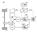
- FIG. 1 is an overall block diagram of a hybrid vehicle according to Embodiment 1 of the present invention.
- hybrid vehicle 100 includes an engine 2, a power split device 4, motor generators 6, 10, a transmission gear 8, a drive shaft 12, and wheels 14.
- Hybrid vehicle 100 further includes power storage device 16, power converters 18 and 20, electronic control unit (hereinafter referred to as “ECU (Electronic Control Unit)”) 22, and shift selection device 24.
- ECU Electronic Control Unit
- the power split device 4 is coupled to the engine 2, the motor generator 6 and the transmission gear 8 and distributes power among them.
- a planetary gear having three rotation shafts of a sun gear, a planetary carrier, and a ring gear can be used as the power split device 4, and these three rotation shafts are connected to the rotation shafts of the motor generator 6, the engine 2, and the transmission gear 8, respectively. Is done.
- the rotation shaft of motor generator 10 is connected to the rotation shaft of transmission gear 8. That is, motor generator 10 and transmission gear 8 have the same rotation shaft, and the rotation shaft is connected to the ring gear of power split device 4.
- engine 2 is incorporated in hybrid vehicle 100 as a power source for driving transmission gear 8 that transmits power to drive shaft 12 and driving motor generator 6.
- the motor generator 6 is incorporated in the hybrid vehicle 100 so as to operate as a generator driven by the engine 2 and to operate as an electric motor that can start the engine 2.
- Motor generator 10 is incorporated in hybrid vehicle 100 as a power source that drives transmission gear 8 that transmits power to drive shaft 12.
- the power storage device 16 is a rechargeable DC power supply, and is configured by a secondary battery such as nickel hydride or lithium ion, for example.
- the power storage device 16 supplies power to the power converters 18 and 20.
- Power storage device 16 is charged by receiving power from power converters 18 and / or 20 when motor generator 6 and / or 10 generates power.
- a large-capacity capacitor can also be used as the power storage device 16, and a power buffer that temporarily stores the power generated by the motor generators 6, 10 and can supply the stored power to the motor generators 6, 10. Anything is acceptable.
- voltage VB of power storage device 16 and current IB input / output to power storage device 16 are detected by a sensor (not shown), and the detected value is output to ECU 22.
- the power converter 18 converts the power generated by the motor generator 6 into DC power based on the signal PWM 1 from the ECU 22 and outputs the DC power to the power storage device 16. Based on signal PWM ⁇ b> 2 from ECU 22, power converter 20 converts the DC power supplied from power storage device 16 into AC power and outputs it to motor generator 10. Power converter 18 converts DC power supplied from power storage device 16 into AC power and outputs it to motor generator 6 based on signal PWM1 when engine 2 is started. Further, power converter 20 converts the electric power generated by motor generator 10 into DC power based on signal PWM 2 and outputs it to power storage device 16 when the vehicle is braked or when acceleration is reduced on a downward slope. Note that power converters 18 and 20 are configured by inverters including switching elements for three phases, for example.
- Motor generators 6 and 10 are AC motors, and are constituted by, for example, three-phase AC synchronous motors in which permanent magnets are embedded in a rotor.
- the motor generator 6 converts the kinetic energy generated by the engine 2 into electric energy and outputs it to the power converter 18.
- Motor generator 6 generates driving force by the three-phase AC power received from power converter 18 and starts engine 2.
- the motor generator 10 generates driving torque of the vehicle by the three-phase AC power received from the power converter 20. Further, the motor generator 10 converts the mechanical energy stored in the vehicle as kinetic energy or positional energy into electric energy and outputs the electric energy to the power converter 20 when the vehicle is braked or when the acceleration on the down slope is reduced.
- the engine 2 converts thermal energy generated by fuel combustion into kinetic energy of a moving element such as a piston or a rotor, and outputs the converted kinetic energy to the power split device 4.
- a moving element such as a piston or a rotor
- the reciprocating motion is converted into a rotational motion via a so-called crank mechanism, and the kinetic energy of the piston is transmitted to the power split device 4.
- the shift selection device 24 is a device for the driver to select one of a plurality of shift ranges.
- the shift selection device 24 includes a shift lever (not shown) that is movable in a P (parking) position, an R (reverse) position, an N (neutral) position, a D (drive) position, and the like.
- the P range, R range, N range, and D range can be selected by adjusting to the position, N position, and D position, respectively.
- the shift selection device 24 outputs a shift signal SP indicating the selected shift range to the ECU 22.
- the D range and the R range are ranges that can be traveled immediately by depressing the accelerator pedal, and are collectively referred to as a “travel range”.
- the P range and the N range are ranges that do not travel even when the accelerator pedal is depressed, and are collectively referred to as “non-traveling range”.
- the ECU 22 controls the power converters 18 and 20 and the engine 2 by software processing by executing a program stored in advance by a CPU (Central Processing Unit) and / or hardware processing by a dedicated electronic circuit. Specifically, ECU 22 generates signals PWM1 and PWM2 for driving power converters 18 and 20, respectively, and outputs the generated signals PWM1 and PWM2 to power converters 18 and 20, respectively. Further, the ECU 22 generates a signal ENG for controlling the engine 2 and outputs the generated signal ENG to the engine 2. Further, ECU 22 calculates the SOC of power storage device 16 based on the detected values of voltage VB and current IB of power storage device 16, and controls the SOC of power storage device 16 based on the calculated value.
- a CPU Central Processing Unit
- the ECU 22 controls the start and stop of the engine 2 based on the start condition and stop condition of the engine 2 set based on the SOC.
- the ECU 22 receives the shift signal SP from the shift selection device 24, and when the travel range (for example, D range) is selected when the vehicle is stopped, the operation duration time of the engine 2 tends to decrease compared to when traveling.
- the stop condition of the engine 2 is set. Further, when the non-traveling range (for example, the P range) is selected, the ECU 22 stops the engine 2 so that the operation duration time of the engine 2 tends to increase compared to when the traveling range is selected when the vehicle is stopped. Set conditions.
- FIG. 2 is a functional block diagram of the ECU 22.
- ECU 22 includes an SOC calculation unit 32, a stop / run determination unit 34, an SOC control unit 36, an engine control unit 38, and a power conversion control unit 40.
- the SOC calculation unit 32 calculates the SOC of the power storage device 16 based on the detected values of the voltage VB and the current IB of the power storage device 16, and outputs the calculation result to the SOC control unit 36.
- Various known methods can be used for calculating the SOC.
- the stop / run determination unit 34 determines whether the vehicle is in a stop state or in a travel state, and outputs the determination result to the SOC control unit 36.
- the term “stop” as used herein refers to a case where the vehicle is stopped when the brake pedal is depressed, and does not mean that the vehicle system is stopped.
- the stop / run determination unit 34 determines stop / run based on, for example, the vehicle speed, the accelerator pedal / brake pedal depression amount, the shift range selected by the shift selection device 24, and the like.
- the SOC control unit 36 controls the SOC of the power storage device 16. Specifically, when the SOC falls below threshold value L, SOC control unit 36 outputs a start command for engine 2 to engine control unit 38 and power conversion control unit 40 when engine 2 is stopped. To do. Then, SOC control unit 36 outputs a power generation command of motor generator 6 to power conversion control unit 40. Further, when the SOC exceeds the threshold value U1 (L ⁇ U1), the SOC control unit 36 outputs a stop command for the engine 2 to the engine control unit 38.
- the SOC control unit 36 receives the shift signal SP from the shift selection device 24, and when the vehicle is stopped and a travel range (for example, D range) is selected, the threshold value is smaller than the threshold value U1.
- a travel range for example, D range
- U1 the threshold value
- U2 L ⁇ U2 ⁇ U1
- a stop command for the engine 2 is output to the engine control unit 38, and the operation mode of the vehicle is set to the eco-run mode.
- the eco-run mode is a mode in which the engine 2 is stopped while the vehicle is stopped, and the engine 2 is started as soon as the vehicle starts running. That is, when the travel range is selected when the vehicle is stopped, the SOC control unit 36 stops the engine 2 when the SOC exceeds the threshold value U2, and then starts the engine 2 when the travel is started.
- the command is output to engine control unit 38 and power conversion control unit 40, and the power generation command of motor generator 6 is output to power conversion control unit 40.
- the SOC control unit 36 does not output a stop command for the engine 2 to the engine control unit 38 until the SOC exceeds the threshold value U1.
- the SOC control unit 36 issues a stop command for the engine 2 when the SOC exceeds a threshold value greater than the threshold value U2. 38.
- the SOC control unit 36 outputs a stop command for the engine 2 to the engine control unit 38.
- the engine control unit 38 generates a signal ENG for controlling the engine 2 and outputs the generated signal ENG to the engine 2.
- the engine control unit 38 receives a start command for the engine 2 from the SOC control unit 36
- the engine control unit 38 generates a signal ENG instructing the operation of the engine 2 and outputs the signal ENG to the engine 2.
- the engine control unit 38 receives a stop command for the engine 2 from the SOC control unit 36
- the engine control unit 38 generates a signal ENG instructing the engine 2 to stop and outputs the signal ENG to the engine 2.
- the power conversion control unit 40 generates signals PWM1 and PWM2 for driving the power converters 18 and 20, respectively, and outputs the generated signals PWM1 and PWM2 to the power converters 18 and 20, respectively.
- power conversion control unit 40 receives a start command for engine 2 from SOC control unit 36
- power conversion control unit 40 generates a signal PWM 1 for powering driving motor generator 6 and outputs the signal PWM 1 to power converter 18.
- power conversion control unit 40 receives a power generation command for motor generator 6 from SOC control unit 36
- power conversion control unit 40 generates signal PWM 1 for regenerative drive of motor generator 6 and outputs the signal PWM 1 to power converter 18.
- power conversion control unit 40 generates signal PWM ⁇ b> 2 for driving motor generator 10 and outputs the signal PWM ⁇ b> 2 to power converter 20.
- the start control of the engine 2 is performed when the engine 2 is stopped.
- the SOC exceeds a threshold value U1 (L ⁇ U1) (engine stop condition)
- stop control of the engine 2 is performed.
- U1 L ⁇ U1
- U2 L ⁇ U2 ⁇ U1
- the engine 2 The stop control is performed. That is, when the travel range is selected when the vehicle is stopped, the stop condition of the engine 2 is changed so that the operation continuation time of the engine 2 decreases compared to when traveling.
- the non-traveling range is selected by the shift selection device 24, when the SOC exceeds a threshold value U1 larger than the threshold value U2, stop control of the engine 2 is performed. That is, when the non-traveling range is selected, the stop condition of the engine 2 is changed so that the operation continuation time of the engine 2 increases as compared with the case where the traveling range is selected when the vehicle is stopped. In other words, when the travel range is selected when the vehicle is stopped, the non-travel range is selected where the stop condition of the engine 2 is changed so that the operation duration time of the engine 2 decreases compared to when traveling. In such a case, the change of the stop condition is canceled.
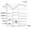
- FIG. 3 is a diagram illustrating an example of the time transition of the SOC of the power storage device 16 when the travel range is selected when the vehicle is stopped.
- the case where the D range is selected is representatively described.
- the operation mode of the vehicle is set to “absolute charging mode”.
- the absolute charging mode is a mode in which the power storage device 16 is charged regardless of whether the vehicle is stopped or traveling. Then, the engine 2 starts and the SOC starts to rise.
- the vehicle has stopped at time t2. It is assumed that the D range is selected even after the vehicle stops.
- the engine 2 operates with priority on the SOC recovery.
- the SOC reaches the threshold value U2 (L ⁇ U2 ⁇ U1) at time t3, the operation mode of the vehicle becomes the “eco-run mode”.
- the eco-run mode is a mode in which the engine 2 is stopped while the vehicle is stopped, and the engine 2 is started together with the start of traveling.
- the engine 2 stops.
- the D range is selected when the vehicle is stopped, the engine 2 is stopped at time t3 when the SOC reaches the threshold value U2 lower than the threshold value U1.
- the SOC of the power storage device 16 decreases (time t3 to t4).
- the SOC falls below the threshold value L again, the engine 2 is started.
- the engine stop threshold value at the time of stopping is lowered from U1 to U2 in order to shorten the engine operating time while the vehicle is stopped.
- the stopping time becomes longer, the engine 2 is stopped and operated. May be repeated frequently. Therefore, in the first embodiment, when a non-traveling range that tends to have a longer stop time is selected, the engine stop threshold is set higher than when the travel range is selected when the vehicle is stopped.
- the engine 2 is restrained from frequently stopping and operating.
- the engine stop threshold value is set to U1. That is, when the non-traveling range is selected, the engine stop threshold is stopped by stopping changing the engine stop threshold value from U1 to U2 as compared with the case where the traveling range is selected when the vehicle is stopped. Achieve higher values.
- FIG. 4 is a diagram illustrating an example of the time transition of the SOC of the power storage device 16 when the non-traveling range is selected when the vehicle is stopped.
- the case where the P range is selected will be representatively described.
- the process up to time t2 is the same as FIG. It is assumed that the P range is selected after stopping at time t2.
- engine 2 operates until the SOC reaches threshold value U1, and at time t3, SOC is restored to threshold value U1 (> U2) and engine 2 is stopped.
- the time until the SOC again falls below the threshold value L due to power consumption by the auxiliary machine, the electric air conditioner, or the like becomes longer. Therefore, frequent stop and operation of the engine 2 are suppressed.
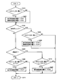
- FIG. 5 is a flowchart for explaining the SOC control processing procedure executed by the ECU 22.
- the processing shown in this flowchart is called from the main routine and executed at regular time intervals or when a predetermined condition is satisfied.
- ECU 22 determines whether or not a non-traveling range is selected based on shift signal SP from shift selection device 24 (step S10). When it is determined that the travel range is not selected, that is, the travel range is selected (NO in step S10), ECU 22 calculates the SOC based on voltage VB and current IB of power storage device 16, and the calculated It is determined whether or not the SOC is higher than the threshold value U1 (step S20). If it is determined that the SOC is higher than threshold value U1 (YES in step S20), ECU 22 turns off the forced charge flag and also turns off the eco-run mode and the absolute charge mode (step S30). Thereby, when the engine 2 is operating at this time, the engine 2 is stopped.
- step S20 If it is determined in step S20 that the SOC is equal to or lower than threshold value U1 (NO in step S20), ECU 22 determines whether or not the SOC is lower than threshold value L (L ⁇ U1) (step S40). ). If it is determined that the SOC is lower than threshold value L (YES in step S40), ECU 22 turns on the forced charging flag (step S50). When it is determined that the SOC is equal to or greater than threshold value L (NO in step S40), ECU 22 proceeds to step S60.
- step S60 the ECU 22 determines whether or not the forced charging flag is turned on.
- the forced charge flag is off (NO in step S60)
- the process proceeds to step S160 without executing the subsequent processes.
- step S60 If it is determined in step S60 that the forced charge flag is on (YES in step S60), ECU 22 determines whether or not the SOC is higher than threshold value U2 (L ⁇ U2 ⁇ U1) (step S60). S70). If it is determined that the SOC is higher than threshold value U2 (YES in step S70), ECU 22 turns on the eco-run mode and turns off the absolute charge mode (step S80). Thereby, when the vehicle is stopped at this time, the engine 2 is stopped.
- step S70 If it is determined in step S70 that the SOC is equal to or lower than threshold value U2 (NO in step S70), ECU 22 determines whether or not the SOC is lower than threshold value L (step S90). If it is determined that the SOC is lower than threshold value L (YES in step S90), ECU 22 turns on the absolute charge mode and turns off the eco-run mode (step S100). Thereby, regardless of whether the vehicle is stopped or traveling, if the engine 2 is stopped at this time, the engine 2 is started. When it is determined in step S90 that the SOC is greater than or equal to threshold value L (NO in step S90), ECU 22 proceeds to step S160.
- step S10 determines whether or not the SOC is lower than the threshold value L (step S120).
- step S120 determines whether or not the SOC is lower than threshold value L (YES in step S120).
- step S120 determines whether or not the SOC is higher than threshold value U1 (step S140). If it is determined that the SOC is higher than threshold value U1 (YES in step S140), ECU 22 turns off the forced charge flag and turns off absolute charge mode (step S150). Thereby, when the engine 2 is operating at this time, the engine 2 is stopped. When it is determined in step S140 that the SOC is equal to or less than threshold value U1 (NO in step S140), ECU 22 proceeds to step S160.
- steps S70 and S80 is “when the travel range is selected when the vehicle is stopped, the internal combustion engine start condition and the stop condition tend to decrease compared with the travel time.
- steps S140 and S150 is “when the non-traveling range is selected, the operation duration time of the internal combustion engine tends to increase compared to when the traveling range is selected when the vehicle is stopped.
- setting conditions correspond to “setting conditions”.
- the operation mode of the vehicle is the eco-run mode. Then the engine 2 stops. Thereby, when SOC falls, the operation
- the non-traveling range is selected, the operation of the engine 2 is continued until the SOC exceeds a threshold value U1 that is larger than the threshold value U2, and when the SOC exceeds the threshold value U1, the engine 2 Stop.
- the overall configuration of the hybrid vehicle according to the second embodiment is the same as that of the hybrid vehicle 100 shown in FIG.
- FIG. 6 is a flowchart for explaining the SOC control processing procedure in the second embodiment.
- the processing shown in this flowchart is also called and executed from the main routine at regular time intervals or when a predetermined condition is satisfied.
- ECU 22 determines whether or not the SOC calculated based on voltage VB and current IB of power storage device 16 is lower than threshold value L (step S210). If it is determined that the SOC is lower than threshold value L (YES in step S210), ECU 22 turns on the forced charging mode during traveling and the forced charging mode during stopping (step S220).
- the forced charging mode during traveling is a mode in which the power storage device 16 is charged by operating the engine 2 during traveling.
- the stop-time forced charging mode is a mode in which the power storage device 16 is charged by operating the engine 2 while the vehicle is stopped. Therefore, in step S220, charging of power storage device 16 is started regardless of whether the vehicle is stopped or traveling.
- ECU 22 proceeds to step S230.
- the ECU 22 determines whether or not the non-traveling range is selected based on the shift signal SP from the shift selection device 24 (step S230). If it is determined that the vehicle is not in the non-traveling range, that is, the travel range is selected (NO in step S230), ECU 22 determines whether or not the vehicle is stopped (step S240).
- step S250 ECU 22 determines whether or not the SOC is higher than threshold value U1 (L ⁇ U1) (step S250). . If it is determined that the SOC is higher than threshold value U1 (YES in step S250), ECU 22 turns off the forced charging mode during travel (step S260). Thereby, engine 2 stops and charging of power storage device 16 stops. When it is determined in step S250 that the SOC is equal to or less than threshold value U1 (NO in step S250), ECU 22 proceeds to step S310.
- step S240 ECU 22 determines whether or not the SOC is higher than threshold value U2 (L ⁇ U2 ⁇ U1) (step S270). . If it is determined that the SOC is higher than threshold value U2 (YES in step S270), ECU 22 turns off the forced charging mode when the vehicle is stopped (step S280). Thereby, engine 2 stops and charging of power storage device 16 stops. When it is determined in step S270 that the SOC is equal to or less than threshold value U2 (NO in step S270), ECU 22 proceeds to step S310.
- step S290 determines whether or not the SOC is higher than threshold value U1 (step S290). If it is determined that the SOC is higher than threshold value U1 (YES in step S290), ECU 22 turns off the forced charging mode during traveling and the forced charging mode during stopping (step S300). Thereby, when the engine 2 is operating at this time, the engine 2 is stopped. If it is determined in step S290 that the SOC is equal to or less than threshold value U1 (NO in step S290), ECU 22 proceeds to step S310.
- steps S270 and S280 is “when the traveling range is selected when the vehicle is stopped, the operating condition of the internal combustion engine tends to decrease compared to when the engine is traveling.
- steps S290 and S300 is “when the non-traveling range is selected, the operation duration of the internal combustion engine tends to increase compared to when the traveling range is selected when the vehicle stops.
- setting conditions correspond to “setting conditions”.
- the same function as in the first embodiment can be realized, and the same effect as in the first embodiment can be obtained.
- the SOC threshold value for stopping the engine 2 started due to the decrease in the SOC is changed depending on the travel / stop and the shift range.
- the engine 2 is started.
- the threshold value of the SOC also changes depending on whether the vehicle is running or stopped. Specifically, when the vehicle is stopped, the SOC threshold value for starting the engine 2 is set to a smaller value than when the vehicle is running. Thereby, the action
- the overall configuration of the hybrid vehicle according to the third embodiment is the same as that of the hybrid vehicle 100 shown in FIG.
- FIG. 7 is a flowchart for explaining the SOC control processing procedure in the third embodiment.
- the processing shown in this flowchart is also called and executed from the main routine at regular time intervals or when a predetermined condition is satisfied.
- this flowchart includes steps S410 to S450 in place of steps S210 and S220 in the flowchart shown in FIG. That is, the ECU 22 determines whether or not the vehicle is stopped (step S410). If it is determined that the vehicle is not stopped, that is, is traveling (NO in step S410), ECU 22 determines whether or not the SOC is lower than threshold value L1 (step S420).
- step S420 If it is determined in step S420 that the SOC is lower than threshold value L1 (YES in step S420), ECU 22 turns on the forced charging mode during travel (step S430). Thereby, the engine 2 is started and the power storage device 16 is charged. When it is determined in step S420 that the SOC is equal to or greater than threshold value L1 (NO in step S420), ECU 22 proceeds to step S230.
- step S410 when it is determined in step S410 that the vehicle is stopped (YES in step S410), ECU 22 determines whether or not the SOC is lower than threshold value L2 (L2 ⁇ L1) (step S440). .
- step S440 If it is determined in step S440 that the SOC is lower than threshold value L2 (YES in step S440), ECU 22 turns on the forced charging mode when the vehicle is stopped (step S450). Thereby, the engine 2 is started and the power storage device 16 is charged.
- step S440 determines that the SOC is greater than or equal to threshold value L2 (NO in step S440)
- ECU 22 proceeds to step S230.
- step S230 is the same as the flowchart shown in FIG.
- the engine 2 is started and the power storage device 16 is charged when the SOC falls below the threshold value L1.
- threshold value L2 L2 ⁇ L1
- L1 threshold value smaller than threshold value L1
- engine 2 is started and power storage device 16 is charged. Therefore, according to the third embodiment, the operation of the engine 2 when the vehicle is stopped can be further suppressed.
- the stop condition of the engine 2 is also changed (steps S230 to S280).
- the engine operation when the vehicle is stopped can be changed only by changing the start condition of the engine 2 (steps S410 to S450). The effect which suppresses is acquired.
- the start and stop of the engine 2 are controlled based on the SOC of the power storage device 16, but other physical quantities related to the state of charge of the power storage device 16 instead of the SOC. May be used.
- the start and stop of the engine 2 may be controlled based on the voltage VB of the power storage device 16. Specifically, the engine 2 is started when the voltage VB falls below the first threshold value corresponding to the start condition of the engine 2, and is greater than the first threshold value corresponding to the stop condition of the engine 2. When the voltage VB exceeds the threshold value of 2, the engine 2 is stopped. When the travel range is selected when the vehicle is stopped, if the voltage VB exceeds the third threshold value that is larger than the first threshold value and smaller than the second threshold value, the engine 2 When the non-traveling range is selected, the engine 2 is stopped when the voltage VB exceeds a threshold value (for example, the second threshold value) larger than the third threshold value. It may be. Further, when the vehicle stops, the first threshold value may be changed to a value smaller than that during traveling.
- a threshold value for example, the second threshold value
- an elapsed time after the charging of the power storage device 16 is started may be used. Specifically, after the engine 2 is started based on the start condition of the engine 2, the engine 2 is stopped when the elapsed time exceeds the threshold time corresponding to the stop condition of the engine 2.
- the threshold time is changed to a shorter time than when traveling, and when the non-travel range is selected, the travel range is selected when the vehicle is stopped. It may be longer than the case (for example, a threshold time during running).
- the series / parallel type hybrid vehicle in which the power of the engine 2 can be divided and transmitted to the transmission gear 8 and the motor generator 6 by the power split device 4 has been described. It can also be applied to other hybrid vehicles. That is, for example, a so-called series-type hybrid vehicle that uses the engine 2 only to drive the motor generator 6 and generates the driving force of the vehicle only by the motor generator 10, or a motor as required using the engine as the main power.
- the present invention is also applicable to a one-motor hybrid vehicle that assists and can charge the power storage device using the motor as a generator.
- the present invention can also be applied to a so-called plug-in hybrid vehicle that can charge the power storage device 16 with a power supply external to the vehicle.
- the R range is included in the travel range.
- the R range may be included in the non-travel range in the case of a system in which the power storage device cannot be charged by operating the engine during reverse travel.
- engine 2 corresponds to an embodiment of “internal combustion engine” in the present invention
- motor generators 6 and 10 correspond to an embodiment of “at least one electric motor” in the present invention
- the ECU 22 corresponds to an embodiment of the “control device” in the present invention.
Landscapes
- Engineering & Computer Science (AREA)
- Transportation (AREA)
- Mechanical Engineering (AREA)
- Chemical & Material Sciences (AREA)
- Combustion & Propulsion (AREA)
- Automation & Control Theory (AREA)
- Hybrid Electric Vehicles (AREA)
- Electric Propulsion And Braking For Vehicles (AREA)
- Control Of Vehicle Engines Or Engines For Specific Uses (AREA)
- Charge And Discharge Circuits For Batteries Or The Like (AREA)
Abstract
Description
図1は、この発明の実施の形態1によるハイブリッド車両の全体ブロック図である。図1を参照して、ハイブリッド車両100は、エンジン2と、動力分割装置4と、モータジェネレータ6,10と、伝達ギヤ8と、駆動軸12と、車輪14とを備える。また、ハイブリッド車両100は、蓄電装置16と、電力変換器18,20と、電子制御ユニット(以下「ECU(Electronic Control Unit)」と称する。)22と、シフト選択装置24とをさらに備える。
図5に示したフローチャートに代えて、以下に示すフローチャートで示される処理手順によっても、実施の形態1と同様のSOC制御を実現することができる。
上記の実施の形態1,2では、SOCの低下により始動したエンジン2を停止させるSOCのしきい値を走行/停止やシフトレンジによって変えたが、この実施の形態3では、エンジン2を始動させるSOCのしきい値も走行時と停車時とで変える。具体的には、車両が停車中のときは、エンジン2を始動させるSOCのしきい値を走行中のときよりも小さい値に設定する。これにより、停車時のエンジン2の作動がさらに抑制される。
Claims (10)
- 蓄電装置(16)と、
内燃機関(2)と、
前記内燃機関により駆動されて前記蓄電装置へ電力を供給するための発電機能と、走行駆動力を発生する機能とを有する少なくとも一つの電動機(6,10)と、
前記蓄電装置の充電状態に関連する物理量から設定される前記内燃機関の始動条件および停止条件に基づいて、前記内燃機関の始動および停止を制御する制御装置(22)と、
走行レンジおよび非走行レンジのいずれかに含まれる複数のシフトレンジのうちの1つを選択するためのシフト選択装置(24)とを備え、
前記制御装置は、停車時に前記走行レンジが選択されている場合には、走行時に比べて前記内燃機関の作動継続時間が減少する傾向に前記始動条件および前記停止条件を設定し、前記非走行レンジが選択されている場合には、停車時に前記走行レンジが選択されている場合に比べて前記作動継続時間が増加する傾向に前記停止条件を設定する、ハイブリッド車両。 - 前記制御装置は、停車時に前記走行レンジが選択されている場合には、走行時に比べて前記作動継続時間が減少する傾向に前記停止条件を変更し、前記非走行レンジが選択されている場合には、前記停止条件の変更を中止する、請求項1に記載のハイブリッド車両。
- 前記物理量は、前記蓄電装置の残存容量であり、
前記制御装置は、前記始動条件に対応する第1のしきい値を前記残存容量が下回ると前記内燃機関を始動させ、停車時に前記走行レンジが選択されている場合には、前記停止条件に対応する、前記第1のしきい値よりも大きい第2のしきい値を前記残存容量が上回ると前記内燃機関を停止させ、前記非走行レンジが選択されている場合には、前記第2のしきい値よりも大きい第3のしきい値を前記残存容量が上回ると前記内燃機関を停止させる、請求項1または請求項2に記載のハイブリッド車両。 - 前記制御装置は、停車時に前記走行レンジが選択されている場合には、前記残存容量が前記第2のしきい値を上回ると、停車中は前記内燃機関を停止させ、かつ、走行開始とともに前記内燃機関を始動させるエコランモードに車両の動作モードを設定し、前記非走行レンジが選択されている場合には、前記エコランモードの設定を解除する、請求項3に記載のハイブリッド車両。
- 前記物理量は、前記蓄電装置の電圧であり、
前記制御装置は、前記始動条件に対応する第1のしきい値を前記電圧が下回ると前記内燃機関を始動させ、停車時に前記走行レンジが選択されている場合には、前記停止条件に対応する、前記第1のしきい値よりも大きい第2のしきい値を前記電圧が上回ると前記内燃機関を停止させ、前記非走行レンジが選択されている場合には、前記第2のしきい値よりも大きい第3のしきい値を前記電圧が上回ると前記内燃機関を停止させる、請求項1または請求項2に記載のハイブリッド車両。 - 前記物理量は、前記蓄電装置の充電が開始されてからの経過時間を含み、
前記制御装置は、前記始動条件に基づき前記内燃機関が始動した後、停車時に前記走行レンジが選択されている場合には、前記停止条件に対応する第1のしきい時間を前記経過時間が超えると前記内燃機関を停止させ、前記非走行レンジが選択されている場合には、前記第1のしきい時間よりも長い第2のしきい時間を前記経過時間が超えると前記内燃機関を停止させる、請求項1または請求項2に記載のハイブリッド車両。 - ハイブリッド車両の制御方法であって、
前記ハイブリッド車両は、
蓄電装置(16)と、
内燃機関(2)と、
前記内燃機関により駆動されて前記蓄電装置へ電力を供給するための発電機能と、走行駆動力を発生する機能とを有する少なくとも一つの電動機(6,10)と、
走行レンジおよび非走行レンジのいずれかに含まれる複数のシフトレンジのうちの1つを選択するためのシフト選択装置(24)とを備え、
前記制御方法は、
前記蓄電装置の充電状態に関連する物理量から設定される前記内燃機関の始動条件および停止条件に基づいて、前記内燃機関の始動および停止を制御するステップと、
停車時に前記走行レンジが選択されている場合に、走行時に比べて前記内燃機関の作動継続時間が減少する傾向に前記始動条件および前記停止条件を設定するステップと、
前記非走行レンジが選択されている場合に、停車時に前記走行レンジが選択されている場合に比べて前記作動継続時間が増加する傾向に前記停止条件を設定するステップとを含む、ハイブリッド車両の制御方法。 - 前記始動条件および前記停止条件を設定するステップは、停車時に前記走行レンジが選択されている場合に、走行時に比べて前記作動継続時間が減少する傾向に前記停止条件を変更するステップを含み、
前記作動継続時間が増加する傾向に前記停止条件を設定するステップは、前記非走行レンジが選択されている場合に、前記停止条件の変更を中止するステップを含む、請求項7に記載のハイブリッド車両の制御方法。 - 前記物理量は、前記蓄電装置の残存容量であり、
前記内燃機関の始動および停止を制御するステップは、
前記始動条件に対応する第1のしきい値を前記残存容量が下回ると前記内燃機関を始動させるステップと、
停車時に前記走行レンジが選択されている場合に、前記停止条件に対応する、前記第1のしきい値よりも大きい第2のしきい値を前記残存容量が上回ると前記内燃機関を停止させるステップと、
前記非走行レンジが選択されている場合に、前記第2のしきい値よりも大きい第3のしきい値を前記残存容量が上回ると前記内燃機関を停止させるステップとを含む、請求項7または請求項8に記載のハイブリッド車両の制御方法。 - 停車時に前記走行レンジが選択されている場合に、前記残存容量が前記第2のしきい値を上回ると、停車中は前記内燃機関を停止させ、かつ、走行開始とともに前記内燃機関を始動させるエコランモードに車両の動作モードを設定するステップと、
前記非走行レンジが選択されている場合に、前記エコランモードの設定を解除するステップとをさらに含む、請求項9に記載のハイブリッド車両の制御方法。
Priority Applications (5)
| Application Number | Priority Date | Filing Date | Title |
|---|---|---|---|
| CN201180069938.3A CN103459221B (zh) | 2011-04-07 | 2011-04-07 | 混合动力车辆及其控制方法 |
| EP11863021.9A EP2695784B1 (en) | 2011-04-07 | 2011-04-07 | Hybrid vehicle and method for controlling the same |
| JP2013508684A JP5630571B2 (ja) | 2011-04-07 | 2011-04-07 | ハイブリッド車両およびその制御方法 |
| PCT/JP2011/058775 WO2012137329A1 (ja) | 2011-04-07 | 2011-04-07 | ハイブリッド車両およびその制御方法 |
| US14/009,995 US8942877B2 (en) | 2011-04-07 | 2011-04-07 | Hybrid vehicle and method for controlling the same |
Applications Claiming Priority (1)
| Application Number | Priority Date | Filing Date | Title |
|---|---|---|---|
| PCT/JP2011/058775 WO2012137329A1 (ja) | 2011-04-07 | 2011-04-07 | ハイブリッド車両およびその制御方法 |
Publications (1)
| Publication Number | Publication Date |
|---|---|
| WO2012137329A1 true WO2012137329A1 (ja) | 2012-10-11 |
Family
ID=46968765
Family Applications (1)
| Application Number | Title | Priority Date | Filing Date |
|---|---|---|---|
| PCT/JP2011/058775 Ceased WO2012137329A1 (ja) | 2011-04-07 | 2011-04-07 | ハイブリッド車両およびその制御方法 |
Country Status (5)
| Country | Link |
|---|---|
| US (1) | US8942877B2 (ja) |
| EP (1) | EP2695784B1 (ja) |
| JP (1) | JP5630571B2 (ja) |
| CN (1) | CN103459221B (ja) |
| WO (1) | WO2012137329A1 (ja) |
Cited By (4)
| Publication number | Priority date | Publication date | Assignee | Title |
|---|---|---|---|---|
| JP2014151718A (ja) * | 2013-02-06 | 2014-08-25 | Toyota Motor Corp | ハイブリッド車両用制御装置 |
| JP2016160751A (ja) * | 2015-02-26 | 2016-09-05 | トヨタ自動車株式会社 | アイドリングストップ制御装置 |
| US9634542B2 (en) | 2013-01-25 | 2017-04-25 | Li-Ho Yao | Electric device for a bicycle |
| CN114286768A (zh) * | 2020-07-31 | 2022-04-05 | 日产自动车株式会社 | 串联混合动力车辆的控制方法以及串联混合动力车辆 |
Families Citing this family (7)
| Publication number | Priority date | Publication date | Assignee | Title |
|---|---|---|---|---|
| US9002552B2 (en) * | 2011-09-21 | 2015-04-07 | GM Global Technology Operations LLC | Compact electric range extender for an electric vehicle |
| CN107128184B (zh) * | 2016-02-26 | 2020-12-25 | 上海恒劲动力科技有限公司 | 燃料电池与储能电池混合动力车控制方法及车系统 |
| DE102016203845B4 (de) * | 2016-03-09 | 2026-01-29 | Bayerische Motoren Werke Aktiengesellschaft | Start-Stopp-Einrichtung zum Einleiten eines automatischen Abschaltvorgangs einer Antriebsmaschine |
| US10005448B2 (en) * | 2016-03-22 | 2018-06-26 | Ford Global Technologies, Llc | Load based engine start-stop control |
| KR101836687B1 (ko) * | 2016-09-01 | 2018-03-08 | 현대자동차주식회사 | 하이브리드 자동차의 제어방법 |
| DE102017204272A1 (de) | 2017-03-15 | 2018-09-20 | Bayerische Motoren Werke Aktiengesellschaft | Vorrichtung zum Aktivieren/Deaktivieren eines Rangierbetriebs eines Antriebs in einem Hybridfahrzeug |
| JP7247285B2 (ja) * | 2021-08-26 | 2023-03-28 | 本田技研工業株式会社 | 車両制御装置 |
Citations (8)
| Publication number | Priority date | Publication date | Assignee | Title |
|---|---|---|---|---|
| JPH11122713A (ja) * | 1997-10-13 | 1999-04-30 | Toyota Motor Corp | 原動機の運転制御装置およびハイブリッド車輌の運転制御装置 |
| JP2001140673A (ja) | 1999-11-19 | 2001-05-22 | Toyota Motor Corp | エンジンの停止・始動制御装置 |
| JP2006077641A (ja) | 2004-09-08 | 2006-03-23 | Mitsubishi Fuso Truck & Bus Corp | ハイブリッド電気自動車の制御装置 |
| JP2007223458A (ja) * | 2006-02-23 | 2007-09-06 | Toyota Motor Corp | ハイブリッド車両 |
| JP2008008215A (ja) | 2006-06-29 | 2008-01-17 | Toyota Motor Corp | 内燃機関制御装置 |
| JP2009018743A (ja) | 2007-07-13 | 2009-01-29 | Toyota Motor Corp | 車両およびその制御方法 |
| JP2010174827A (ja) | 2009-01-30 | 2010-08-12 | Daihatsu Motor Co Ltd | アイドルストップ制御装置 |
| JP2010202119A (ja) * | 2009-03-05 | 2010-09-16 | Toyota Motor Corp | ハイブリッド車両およびその制御方法 |
Family Cites Families (2)
| Publication number | Priority date | Publication date | Assignee | Title |
|---|---|---|---|---|
| JP3776610B2 (ja) * | 1998-12-08 | 2006-05-17 | トヨタ自動車株式会社 | パワートレーンの制御装置 |
| JP3791234B2 (ja) * | 1999-03-17 | 2006-06-28 | 株式会社デンソー | ハイブリッド車用空調装置。 |
-
2011
- 2011-04-07 US US14/009,995 patent/US8942877B2/en active Active
- 2011-04-07 WO PCT/JP2011/058775 patent/WO2012137329A1/ja not_active Ceased
- 2011-04-07 CN CN201180069938.3A patent/CN103459221B/zh not_active Expired - Fee Related
- 2011-04-07 JP JP2013508684A patent/JP5630571B2/ja not_active Expired - Fee Related
- 2011-04-07 EP EP11863021.9A patent/EP2695784B1/en not_active Not-in-force
Patent Citations (8)
| Publication number | Priority date | Publication date | Assignee | Title |
|---|---|---|---|---|
| JPH11122713A (ja) * | 1997-10-13 | 1999-04-30 | Toyota Motor Corp | 原動機の運転制御装置およびハイブリッド車輌の運転制御装置 |
| JP2001140673A (ja) | 1999-11-19 | 2001-05-22 | Toyota Motor Corp | エンジンの停止・始動制御装置 |
| JP2006077641A (ja) | 2004-09-08 | 2006-03-23 | Mitsubishi Fuso Truck & Bus Corp | ハイブリッド電気自動車の制御装置 |
| JP2007223458A (ja) * | 2006-02-23 | 2007-09-06 | Toyota Motor Corp | ハイブリッド車両 |
| JP2008008215A (ja) | 2006-06-29 | 2008-01-17 | Toyota Motor Corp | 内燃機関制御装置 |
| JP2009018743A (ja) | 2007-07-13 | 2009-01-29 | Toyota Motor Corp | 車両およびその制御方法 |
| JP2010174827A (ja) | 2009-01-30 | 2010-08-12 | Daihatsu Motor Co Ltd | アイドルストップ制御装置 |
| JP2010202119A (ja) * | 2009-03-05 | 2010-09-16 | Toyota Motor Corp | ハイブリッド車両およびその制御方法 |
Non-Patent Citations (1)
| Title |
|---|
| See also references of EP2695784A4 |
Cited By (5)
| Publication number | Priority date | Publication date | Assignee | Title |
|---|---|---|---|---|
| US9634542B2 (en) | 2013-01-25 | 2017-04-25 | Li-Ho Yao | Electric device for a bicycle |
| JP2014151718A (ja) * | 2013-02-06 | 2014-08-25 | Toyota Motor Corp | ハイブリッド車両用制御装置 |
| JP2016160751A (ja) * | 2015-02-26 | 2016-09-05 | トヨタ自動車株式会社 | アイドリングストップ制御装置 |
| US9821811B2 (en) | 2015-02-26 | 2017-11-21 | Toyota Jidosha Kabushiki Kaisha | Idling stop control device |
| CN114286768A (zh) * | 2020-07-31 | 2022-04-05 | 日产自动车株式会社 | 串联混合动力车辆的控制方法以及串联混合动力车辆 |
Also Published As
| Publication number | Publication date |
|---|---|
| US8942877B2 (en) | 2015-01-27 |
| JPWO2012137329A1 (ja) | 2014-07-28 |
| EP2695784A1 (en) | 2014-02-12 |
| EP2695784B1 (en) | 2017-01-11 |
| EP2695784A4 (en) | 2015-06-17 |
| US20140039744A1 (en) | 2014-02-06 |
| CN103459221A (zh) | 2013-12-18 |
| JP5630571B2 (ja) | 2014-11-26 |
| CN103459221B (zh) | 2016-01-06 |
Similar Documents
| Publication | Publication Date | Title |
|---|---|---|
| JP5630571B2 (ja) | ハイブリッド車両およびその制御方法 | |
| JP5585666B2 (ja) | ハイブリッド車両およびその制御方法 | |
| EP2722243B1 (en) | Hybrid vehicle and method for controlling hybrid vehicle | |
| JP5825288B2 (ja) | ハイブリッド車両 | |
| JP2009143563A (ja) | ハイブリッド車両 | |
| JP5825287B2 (ja) | ハイブリッド車両 | |
| JP6213497B2 (ja) | ハイブリッド車両 | |
| JP6179504B2 (ja) | ハイブリッド車両 | |
| JPWO2013065166A1 (ja) | 車両および車両の制御方法 | |
| JP5696791B2 (ja) | 車両および車両の制御方法 | |
| JPWO2013046313A1 (ja) | 車両および車両の制御方法 | |
| JP6361299B2 (ja) | ハイブリッド車両 | |
| JP5879768B2 (ja) | ハイブリッド車両 | |
| JPWO2012137297A1 (ja) | 車両および車両用制御方法 | |
| JP2013006430A (ja) | ハイブリッド車両およびその制御方法 | |
| JP2015013517A (ja) | 車両の制御装置 | |
| JP2015009746A (ja) | ハイブリッド車両の制御装置 | |
| JP2016155486A (ja) | ハイブリッド車両 |
Legal Events
| Date | Code | Title | Description |
|---|---|---|---|
| 121 | Ep: the epo has been informed by wipo that ep was designated in this application |
Ref document number: 11863021 Country of ref document: EP Kind code of ref document: A1 |
|
| ENP | Entry into the national phase |
Ref document number: 2013508684 Country of ref document: JP Kind code of ref document: A |
|
| WWE | Wipo information: entry into national phase |
Ref document number: 14009995 Country of ref document: US |
|
| NENP | Non-entry into the national phase |
Ref country code: DE |
|
| REEP | Request for entry into the european phase |
Ref document number: 2011863021 Country of ref document: EP |
|
| WWE | Wipo information: entry into national phase |
Ref document number: 2011863021 Country of ref document: EP |