WO2012137452A1 - Élément optique et élément optique à diffraction multicouche - Google Patents
Élément optique et élément optique à diffraction multicouche Download PDFInfo
- Publication number
- WO2012137452A1 WO2012137452A1 PCT/JP2012/002230 JP2012002230W WO2012137452A1 WO 2012137452 A1 WO2012137452 A1 WO 2012137452A1 JP 2012002230 W JP2012002230 W JP 2012002230W WO 2012137452 A1 WO2012137452 A1 WO 2012137452A1
- Authority
- WO
- WIPO (PCT)
- Prior art keywords
- resin layer
- refractive index
- optical element
- resin
- transparent substrate
- Prior art date
- Legal status (The legal status is an assumption and is not a legal conclusion. Google has not performed a legal analysis and makes no representation as to the accuracy of the status listed.)
- Ceased
Links
Images


Classifications
-
- G—PHYSICS
- G02—OPTICS
- G02B—OPTICAL ELEMENTS, SYSTEMS OR APPARATUS
- G02B5/00—Optical elements other than lenses
- G02B5/18—Diffraction gratings
- G02B5/1866—Transmission gratings characterised by their structure, e.g. step profile, contours of substrate or grooves, pitch variations, materials
-
- B—PERFORMING OPERATIONS; TRANSPORTING
- B29—WORKING OF PLASTICS; WORKING OF SUBSTANCES IN A PLASTIC STATE IN GENERAL
- B29D—PRODUCING PARTICULAR ARTICLES FROM PLASTICS OR FROM SUBSTANCES IN A PLASTIC STATE
- B29D11/00—Producing optical elements, e.g. lenses or prisms
- B29D11/0073—Optical laminates
-
- B—PERFORMING OPERATIONS; TRANSPORTING
- B29—WORKING OF PLASTICS; WORKING OF SUBSTANCES IN A PLASTIC STATE IN GENERAL
- B29D—PRODUCING PARTICULAR ARTICLES FROM PLASTICS OR FROM SUBSTANCES IN A PLASTIC STATE
- B29D11/00—Producing optical elements, e.g. lenses or prisms
- B29D11/0074—Production of other optical elements not provided for in B29D11/00009- B29D11/0073
- B29D11/00769—Producing diffraction gratings
-
- G—PHYSICS
- G02—OPTICS
- G02B—OPTICAL ELEMENTS, SYSTEMS OR APPARATUS
- G02B5/00—Optical elements other than lenses
- G02B5/18—Diffraction gratings
- G02B5/1876—Diffractive Fresnel lenses; Zone plates; Kinoforms
Definitions
- the present invention relates to an optical element and a multilayer diffractive optical element which are used for a camera, a video tape recorder, and the like.
- chromatic aberration is reduced by using lenses formed from glass materials having different dispersion properties in combination.
- the chromatic aberration which appears on an axis, is corrected by using a positive lens formed from a glass material having small dispersion and a negative lens formed from a glass material having large dispersion in combination.
- the structure and the number of lenses are restricted and/or in the case in which glass materials to be used are restricted, it is difficult in some cases to sufficiently correct the chromatic aberration.
- the chromatic aberration can be reduced by using a small number of lenses.
- This combination uses a physical phenomenon in which on a refracting surface and a diffracting surface of the optical system, chromatic aberration with respect to light having a certain reference wavelength appears in directions opposite to each other.
- chromatic aberration with respect to light having a certain reference wavelength appears in directions opposite to each other.
- one ray of light incident on the diffractive optical element is divided into a plurality of rays of different orders by a diffraction effect.
- diffracted light of order other than a design order forms an image on a place different from that of an image of light of the design order, thereby causing flare.
- the low refractive index and high dispersion optical material disclosed in Japanese Patent Laid-Open No. 2008-203821 can be obtained by curing a composite material by ultraviolet radiation in which a transparent conductive metal oxide having a high refractive index dispersion and a low secondary dispersion property is mixed and dispersed as fine particles in a binder resin having a low refractive index.
- a transparent conductive metal oxide such as ITO, has been used as the transparent conductive metal oxide.
- a multilayer diffractive optical element which includes as a part thereof, a dispersing material of transparent conductive fine particles of ITO or the like shows a high diffraction efficiency state in the entire visible range.
- the optical properties of an ITO dispersing material are changed in accordance with use environment. Therefore, it is difficult to obtain a high diffraction efficiency of the multilayer diffractive optical element in the entire visible range.
- the present invention provides an optical element and a multilayer diffractive optical element, each of which can maintain a high diffraction efficiency state in the entire visible range without causing any changes with time.
- a first resin layer formed by energy curing of a resin composition containing a monomer and fine particles of a transparent conductive substance and a second resin layer which permeates oxygen are laminated on a transparent substrate, and a space for supplying oxygen is provided on the second resin layer.
- a first resin layer which includes a resin formed by energy curing of a resin composition containing a monomer and fine particles of a transparent conductive substance and which has a diffraction grating shape and a second resin layer which permeates oxygen and which has at least one diffraction grating shape surface are laminated on a transparent substrate so that the diffraction grating shape of the first resin layer and that of the second resin layer face each other, and a space for supplying oxygen is provided on the second resin layer.
- a first resin layer which includes a resin formed by energy curing of a resin composition containing a monomer and fine particles of a transparent conductive substance and which has at least one diffraction grating shape surface is laminated so that the diffraction grating shape of the transparent substrate and that of the first resin layer face each other, and a space for supplying oxygen is provided on the first resin layer.
- Fig. 1A is a schematic view showing one embodiment of a multilayer diffractive optical element of the present invention.
- Fig. 1B is a schematic view showing another embodiment of the multilayer diffractive optical element of the present invention.
- Fig. 1C is a schematic view showing another embodiment of the multilayer diffractive optical element of the present invention.
- Fig. 1D is a schematic view showing another embodiment of the multilayer diffractive optical element of the present invention.
- Fig. 2A is a schematic view showing a method for forming a sample for refractive-index measurement.
- Fig. 2B is a schematic view showing the method for forming a sample for refractive-index measurement.
- Fig. 2C is a schematic view showing the method for forming a sample for refractive-index measurement.
- Fig. 3A is a schematic view showing a method for forming a multilayer diffractive optical element for evaluation of diffraction efficiency.
- Fig. 3B is a schematic view showing the method for forming a multilayer diffractive optical element for evaluation of diffraction efficiency.
- Fig. 4A is a schematic view showing the method for forming a multilayer diffractive optical element for evaluation of diffraction efficiency.
- Fig. 4B is a schematic view showing the method for forming a multilayer diffractive optical element for evaluation of diffraction efficiency.
- Fig. 4C is a schematic view showing the method for forming a multilayer diffractive optical element for evaluation of diffraction efficiency.
- FIG. 5 is a schematic view showing the structure of a sample for refractive-index measurement of Example 2.
- Fig. 6 is a schematic view showing the structure of a multilayer diffractive optical element for evaluation of diffraction efficiency of Example 2.
- Fig. 7 is a schematic view showing the structure of a sample for refractive-index measurement of Comparative Example 1.
- Fig. 8 is a schematic view showing the structure of a multilayer diffractive optical element for evaluation of diffraction efficiency of Comparative Example 1.
- an optical material of a resin is formed by curing a resin composition containing ITO fine particles and a monomer by irradiation of ultraviolet rays and visible light having a short wavelength.
- a resin composition containing ITO fine particles and a monomer by irradiation of ultraviolet rays and visible light having a short wavelength, radicals are generated.
- the radicals thus generated are trapped by the ITO fine particles and function as carriers of ITO.
- the ITO is reduced by the radicals, and as a result, optical properties, such as the refractive index and the absorption of light, are changed, so that the performance of the optical element is influenced.
- a high diffraction efficiency state of the optical element at an initial stage is shifted from diffraction conditions by the change in refractive index of an ITO dispersing material, and as a result, the diffraction efficiency is degraded.
- the present inventors found out that when oxygen in the air is incorporated and is brought into contact with the ITO dispersing material so as to eliminate the radicals trapped by the ITO fine particles by oxygen and so as to return the reduced ITO to its original state by oxidation thereof, the optical properties, such as the refractive index and the absorption of light, can be improved.
- a first resin layer formed by energy curing of a resin composition containing a monomer and fine particles of a transparent conductive substance and a second resin layer which permeates oxygen are laminated on a transparent substrate, and a space for supplying oxygen is provided on the second resin layer.
- an optical element has the structure in which a second resin layer and a first resin layer formed by energy curing of a resin composition containing a monomer and fine particles of a transparent conductive substance are laminated on a transparent substrate and in which a space for supplying oxygen is provided on the first resin layer.
- a first resin layer formed by energy curing of a resin composition containing a monomer and fine particles of a transparent conductive substance and a second resin layer which permeates oxygen are laminated on a first transparent substrate, a second transparent substrate located above the second resin layer with a space of a gas containing oxygen provided therebetween is fixed to the first transparent substrate by a spacer, and the space of a gas containing oxygen is a closed space surrounded by the second resin layer, the second transparent substrate, and the spacer.
- a second resin layer and a first resin layer formed of a resin composition containing fine particles of a transparent conductive substance are laminated on a first transparent substrate, and a second transparent substrate located above the first resin layer with a space of a gas containing oxygen provided therebetween is fixed to the first transparent substrate by a spacer, and the space of a gas containing oxygen is a closed space surrounded by the first resin layer, the second transparent substrate, and the spacer.
- the space for supplying oxygen is provided on the second resin layer, the refractive index and the transmittance of a material in which the transparent conductive substance is dispersed in a long wavelength region can be suppressed from being changed by ultraviolet rays and visible light.
- the first resin layer preferably includes a low refractive index and high dispersion material
- the second resin layer preferably includes a high refractive index and low dispersion material
- the first resin layer and the second resin layer each preferably include an energy curing resin, and the resin is preferably at least one radical curing resin selected from an acrylic resin, a vinyl resin, and an epoxy resin.
- a first resin layer formed by energy curing of a resin composition containing a monomer and fine particles of a transparent conductive substance and a second resin layer which permeates oxygen are laminated on a transparent substrate, and a space for supplying oxygen is provided on the second resin layer.
- the transparent substrate for example, a glass substrate and a glass lens may be used.
- the resin composition for forming the first resin layer is a composition containing the fine particles of a transparent conductive substance, the resin composition, a surface treatment agent or a dispersing agent (surfactant), and the like.
- the transparent conductive substance for the fine particles contained in the resin composition forming the first resin layer of the present invention for example, zinc oxide, indium oxide, tin oxide, antimony oxide, indium tin oxide (ITO), antimony-doped tin oxide (ATO), zinc-doped indium oxide (IZO), aluminum-doped zinc oxide (AZO), and fluorine-doped tin oxide (FTO) may be mentioned.
- indium tin oxide (ITO) is preferably used.
- indium tin oxide (ITO) is a substance which has a small secondary dispersion property (theta gF ) and which is best to maintain the transparency.
- the use of this new substance is not limited.
- various surface treatment agents or dispersing agents are preferably used on the surfaces of the fine particles.
- the average fine particle diameter of the fine particles a fine particle diameter having no adverse influences on the optical transmittance, the optical scattering, and the like is preferable, and the average fine particle diameter is in a range of 1 to 100 nm, preferably in a range of 2 to 30 nm, and particularly preferably in a range of 2 to 20 nm.
- the average fine particle diameter is 20 nm or less, when the distribution in fine particle diameter is broad, and the volume fraction of fine particles having a fine particle diameter of more than 30 nm is 5 percent or more of the total fine particles, the optical scattering is considerably adversely influenced besides the case in which the fine particles are agglomerated.
- a surface treatment is preferably performed on the fine particles, if needed.
- the surface treatment may be performed at the stage of synthesis of fine particles or at the stage of production thereof or may be separately performed after the fine particles are obtained.
- the volume fraction of the fine particles of a transparent conductive substance in the resin composition for forming the first resin layer is in a range of 1 to 29 percent by volume and preferably in a range of 5 to 23 percent by volume.
- the dispersing solvent used in the present invention in order to dissolve the monomer (hereinafter referred to as the "binder component" in some cases) or to disperse the fine particles in the solvent, and if needed, in order to dissolve a surface treatment agent or a dispersing agent, for example, there may be mentioned aromatic hydrocarbons, such as toluene, benzene, and xylene; alcohols, such ethanol and isopropanol; alicyclic hydrocarbons, such as cyclohexane; acetates, such as ethyl acetate and butyl acetate; ketones, such as acetone and methyl ethyl ketone; amides, such as dimethylformamide (DMF), dimethylacetamide (DMAc), and N-methyl pyrrolidone (NMP); aliphatic hydrocarbons, such as hexane and octane; ethers, such as diethyl ether and but
- the dispersing solvent may be selected in accordance with the affinities of fine particles, a surface treatment agent, and a dispersing agent to be used, and the dispersing solvents may be used alone, or at least two types thereof may be used in combination as long as the dispersibility is not degraded.
- the dispersing solvent is removed in a process for forming the resin composition.
- the content of the dispersing solvent contained in the resin composition for forming the first resin layer with respect to the resin composition for forming the first resin layer is 0.2 percent by weight or less and preferably 0.05 percent by weight or less.
- the surface treatment agent or the dispersing agent (surfactant) for uniformly dispersing fine particles without causing agglomeration thereof the following will be preferably used.
- the surface treatment agent or the dispersing agent used in the present invention pigment derivatives or a resin type or an active agent type compound may be preferably used.
- a cationic, a weak cationic, a nonionic, or an amphoteric surfactant is effectively used.
- Disper BYK 161, 162, 163, and 164 of Disper BYK Series (manufactured by BYK Japan K.K.), Solsperse 3000, 9000, 17000, 20000, 24000, and 41090 of Solsperse Series (manufactured by Zeneca Co., Ltd.), and a PO or an EO modified compound of an alkyl amine, such as TAMN-15, of TAMN Series (manufactured by Nikko Chemicals Co., Ltd.).
- the dispersing agents may be used alone, or at least two types thereof may be used in combination.
- the content of the surface treatment agent or the dispersing agent, which is contained in the resin composition for forming the first resin layer is changed roughly in accordance with the type of surface treatment agent or dispersing agent, the type of fine particles, the surface area thereof (diameters of fine particles), the type of dispersing resin in which fine particles are mixed, the type of dispersing solvent, and the like, the content with respect to the weight of the fine particles is in a range of 0.1 to 25.0 percent by weight and preferably in a range of 4.0 to 20.0 percent by weight.
- the content of the dispersing agent is more than 25.0 percent by weight, cloudiness occurs thereby, and optical scattering also occurs; hence, the properties (refractive index, Abbe's number, secondary dispersion property, elastic modulus, and the like) of the composition which are obtained by the fine particles contained therein are unnecessarily degraded.
- the monomer functioning as the binder component to be formed into the base resin a monomer having good compatibility with the solvent in which, for example, the metal oxide fine particles having transparency and conductivity are dispersed, the surface treatment agent, and the dispersing agent is preferably selected.
- any monomer may be used as long as having at least one double bond or triple bond, and as particular examples of a monomer or an oligomer of an unsaturated group-containing compound, for example, there may be mentioned 1,4-divinylcyclohexane, 1,4-cyclohexanedimethanol divinyl ether, 4,4-dimethyl-hept-1-en-6-yne, divinylbenzene, 1,6-divinylnaphthalene, N-vinyl pyrrolidone, N-vinylcaprolactam, ethoxylated bisphenol A divinyl ether, and propoxylated bisphenol A divinyl ether; monofunctional acrylates and methacrylates, such as a polyethylene glycol mono-(meth)acrylate, a polypropylene glycol mono-(meth)acrylate, and a phenoxyethyl (meth)acrylate; compounds each formed in such a way that ethylene oxide or propylene
- a fluorine compound as examples of suitable raw materials of the resins, for example, a fluorinated acrylic, a fluorinated methacrylic, a fluorinated epoxy, and a fluorinated vinyl monomer may be mentioned.
- a fluororesin polymer may also be selected.
- a copolymer among copolymers manufactured by Central Glass Co., Ltd., for example, copolymers sold under the trade names, No. 702C, 703C, 704C, 705C, 706C and 707C may also be mentioned.
- Fluorine monomers each used as a binder component having a polymerization functional group may be used alone, or at least two types thereof may also be used in combination. In addition, at least two of the acrylates and/or methacrylates mentioned above may also be used in combination.
- the content of the monomer contained in the resin composition for forming the first resin layer with respect to the resin composition for forming the first resin layer is in a range of 30 to 99 percent by weight and preferably in a range of 37 to 78 percent by weight.
- polymerization can be performed by exciting an initiator using energy, such as plasma, heat, radioactive rays, and ultraviolet rays, in consideration of replica formation of a lens or the like, a photo-curing method is preferable.
- energy such as plasma, heat, radioactive rays, and ultraviolet rays
- a usable photopolymerization initiator in particular, for example, 2-benzyl-2-dimethylamino-1-(4-morpholinophenyl)-1-butanone, 1-hydroxycyclohexyl phenyl ketone, bis(2,4,6-trimethyl benzoyl)-phenylphosphine oxide, 4-phenyl benzophenone, 4-phenoxy benzophenone, 4,4'-diphenyl benzophenone, and 4,4'-diphenoxy benzophenone may be mentioned as suitable compounds.
- 1-hydroxycyclohexyl phenyl ketone is preferably used.
- the content of the photopolymerization initiator is preferably set in a range of 0.01 to 10.00 percent by weight with respect to that of the binder component.
- the photopolymerization initiators may be used alone, or at least two types thereof may also be used in combination.
- a high refractive index and low dispersion resin composition for forming the second resin layer which permeates oxygen is a composition containing fine particles of a high refractive index and low dispersion substance, a resin composition, a surface treatment agent or a dispersing agent (surfactant), and the like.
- the high refractive index and low dispersion fine particles contained in a resin composition forming the second resin layer of the present invention for example, aluminum oxide and zirconium oxide may be mentioned.
- a high refractive index and low dispersion substance appears in the future, the use of the above substance is not limited.
- a fluorine resin or the like is used for the resin of the second resin layer, by the difference in refractive index thereof, fine particles which increase the refractive index may not be required in some cases.
- various surface treatment agents or dispersing agents are preferably used on the surfaces of the fine particles.
- the average fine particle diameter of the fine particles a fine particle diameter having no adverse influences on the optical transmittance, the optical scattering, and the like is preferable, and the average fine particle diameter is in a range of 1 to 100 nm, preferably in a range of 2 to 30 nm, and particularly preferably in a range of 2 to 20 nm.
- the average fine particle diameter is 20 nm or less, when the distribution in fine particle diameter is broad, and the volume fraction of fine particles having a fine particle diameter of more than 30 nm is 5 percent or more of the total fine particles, the optical scattering is considerably adversely influenced besides the case in which the fine particles are agglomerated.
- a surface treatment is preferably performed on the fine particles, if needed.
- the surface treatment may be performed at the stage of synthesis of fine particles or at the stage of production thereof or may be separately performed after the fine particles are obtained.
- the volume fraction of the fine particles of the transparent conductive substance in the resin composition for forming the second resin layer is in a range of 1 to 29 percent by volume and preferably in a range of 5 to 23 percent by volume.
- the dispersing solvent used in the present invention in order to dissolve the monomer (hereinafter referred to as the "binder component" in some cases) or to disperse the fine particles in the solvent, and if needed, in order to dissolve a surface treatment agent or a dispersing agent, for example, there may be mentioned aromatic hydrocarbons, such as toluene, benzene, and xylene; alcohols, such ethanol and isopropanol; alicyclic hydrocarbons, such as cyclohexane; acetates, such as ethyl acetate and butyl acetate; ketones, such as acetone and methyl ethyl ketone; amides, such as DMF, DMAc, and NMP; aliphatic hydrocarbons, such as hexane and octane; ethers, such as diethyl ether and butyl carbitol; and halogenated hydrocarbon, such as dichloromethane, such as
- the dispersing solvent may be selected in accordance with the affinities of fine particles, a surface treatment agent, and a dispersing agent to be used, and the dispersing solvents may be used alone, or at least two types thereof may be used in combination as long as the dispersibility is not degraded.
- the dispersing solvent is removed in a process for forming the resin composition.
- the content of the dispersing solvent contained in the resin composition for forming the second resin layer with respect to the resin composition for forming the second resin layer is 0.2 percent by weight or less and preferably 0.05 percent by weight or less.
- the surface treatment agent or the dispersing agent (surfactant) for uniformly dispersing fine particles without causing agglomeration thereof the following will be preferably used.
- the surface treatment agent or the dispersing agent used in the present invention pigment derivatives or a resin type or an active agent type compound may be preferably used.
- a cationic, a weak cationic, a nonionic, or an amphoteric surfactant is effectively used.
- Disper BYK 161, 162, 163, and 164 of Disper BYK Series (manufactured by BYK Japan K.K.), Solsperse 3000, 9000, 17000, 20000, 24000, and 41090 of Solsperse Series (manufactured by Zeneca Co., Ltd.), and a PO or an EO modified compound of an alkyl amine, such as TAMN-15, of TAMN Series (manufactured by Nikko Chemicals Co., Ltd.).
- the dispersing agents may be used alone, or at least two types thereof may be used in combination.
- the content of the surface treatment agent or the dispersing agent, which is contained in the resin composition for forming the second resin layer, is changed roughly in accordance with the type of surface treatment agent or dispersing agent, the type of fine particles, the surface area thereof (diameters of fine particles), the type of dispersing resin in which fine particles are mixed, the type of dispersing solvent, and the like.
- the content of the surface treatment agent or the dispersing agent with respect to the weight of the fine particles is in a range of 0.1 to 25.0 percent by weight and preferably in a range of 4.0 to 20.0 percent by weight.
- the content of the dispersing agent is more than 25.0 percent by weight, cloudiness occurs thereby, and optical scattering also occurs; hence, the properties (refractive index, Abbe's number, elastic modulus, and the like) of the composition which are obtained by the fine particles contained therein are unnecessarily degraded.
- the monomer functioning as the binder component to be formed into the base resin a monomer having good compatibility with the solvent in which, for example, the metal oxide fine particles having transparency and conductivity are dispersed, the surface treatment agent, and the dispersing agent is preferably selected.
- any monomer may be used as long as having at least one double bond or triple bond, and as particular examples of a monomer or an oligomer of an unsaturated group-containing compound, for example, there may be mentioned 1,4-divinylcyclohexane, 1,4-cyclohexanedimethanol divinyl ether, 4,4-dimethyl-hept-1-en-6-yne, divinylbenzene, 1,6-divinylnaphthalene, N-vinyl pyrrolidone, N-vinylcaprolactam, ethoxylated bisphenol A divinyl ether, and propoxylated bisphenol A divinyl ether; monofunctional acrylates and methacrylates, such as a polyethylene glycol mono-(meth)acrylate, a polypropylene glycol mono-(meth)acrylate, and a phenoxyethyl (meth)acrylate; compounds each formed in such a way that ethylene oxide or propylene
- Fluorine monomers each used as the binder component and having a polymerization functional group may be used alone, or at least two thereof may also be used in combination. In addition, at least two of the acrylates and/or methacrylates mentioned above may also be used in combination.
- the content of the monomer contained in the resin composition for forming the second resin layer with respect to the resin composition for forming the second resin layer is 30 to 99 percent by weight and preferably 37 to 78 percent by weight.
- polymerization can be performed by exciting an initiator using energy, such as plasma, heat, radioactive rays, and ultraviolet rays, in consideration of replica formation of a lens or the like, a photo-curing method is preferable.
- energy such as plasma, heat, radioactive rays, and ultraviolet rays
- a usable photopolymerization initiator in particular, for example, 2-benzyl-2-dimethylamino-1-(4-morpholinophenyl)-1-butanone, 1-hydroxycyclohexyl phenyl ketone, bis(2,4,6-trimethyl benzoyl)-phenylphosphine oxide, 4-phenyl benzophenone, 4-phenoxy benzophenone, 4,4'-diphenyl benzophenone, and 4,4'-diphenoxy benzophenone may be mentioned as suitable compounds.
- 1-hydroxycyclohexyl phenyl ketone is preferably used.
- the content of the photopolymerization initiator is preferably set in a range of 0.01 to 10.00 percent by weight with respect to the binder component.
- the photopolymerization initiators may be used alone, or at least two types thereof may also be used in combination.
- Step of preparing optical material as resin composition Next, a step of preparing an optical material as the resin composition in the present invention will be described. The case in which a photopolymerizable binder component is used will be representatively described.
- a suitable surface treatment agent or dispersing agent is first dissolved in a selected solvent, and fine particles are then added thereto, a shearing force is applied to crush agglomerates of the fine particles, and remaining agglomerates are removed by centrifugal separation and filtering, so that a uniform particulate dispersion liquid is obtained.
- a selected photopolymerizable binder component and a photopolymerization initiator are dissolved.
- the solvent and the surface treatment agent or the dispersing agent are preferably used in combination so that the dispersion state of the fine particles is more unlikely to be degraded by addition of the binder component.
- agglomerated fine particles can be removed. After the dissolution is completely performed, a state in which the fine particles are preferably dispersed without precipitation thereof and the like is confirmed, and the solvent is then removed using an evaporator.
- the degree of reduced pressure be appropriately adjusted in accordance with the boiling point of the solvent, the remaining amount thereof, and the like. By rapid evaporation and removal of the solvent, the degree of agglomeration of the fine particles may be degraded, and the dispersibility thereof may be degraded in some cases.
- heating may also be performed so as not to degrade the dispersibility. As described above, the optical material of the present invention is obtained.
- a residual solvent which cannot be removed may be contained in the optical material thus obtained in some cases. If the content of the residual solvent is larger than 0.1 percent by weight, it seems that an effect of promoting fine particle migration at the time of energy curing is generated, and the gradient index (GI) and light scattering are increased. Therefore, the content of the residual solvent is preferably 0.1 percent by weight or less.
- the degree of reduced pressure is excessively high, and when heating is simultaneously performed under reduced pressure, or a step under reduced pressure is performed for a long period of time, the surface treatment agent, the dispersing agent, and monomers such as the binder component, which are added as described above, may also be distilled off together with the solvent. Therefore, the degree of reduced pressure, the temperature, the time, and the like must be appropriately adjusted in consideration of the molecular weight, the boiling point, the sublimability, and the like of each component.
- the substrate When the first and the second resin layers each having a small thickness are formed on a light transparent material used for the substrate, for example, a glass plate is used as the substrate.
- a metal material is used for a mold corresponding to a fine diffraction grating structure, an optical material of a resin composition having fluidity is poured into the metal mold and is lightly pressed, so that mold forming is performed. While the above state is maintained, this optical material is photo-polymerized.
- the light irradiation for this photopolymerization reaction is performed using light having a preferable wavelength, in general, such as ultraviolet rays or visible light, in accordance with the mechanism in which radicals are generated using a photopolymerization initiator.
- light irradiation is uniformly performed on a molded raw material, such as the resin composition for optical material preparation, with the light transparent material used for the substrate, in particular, a glass plate, provided therebetween.
- the amount of light thus irradiated is appropriately selected in accordance with the mechanism in which radicals are generated using a photopolymerization initiator or in accordance with the content ratio of the contained photopolymerization initiator.
- the second resin layer which permeates oxygen is laminated.
- a material used for the second resin layer is determined by the optical constant of the first resin layer, and after curing, the second resin layer has a high refractive index and low dispersion value relative to that of the first resin layer.
- a resin itself or a resin containing fine particles of zirconia or alumina is used as the material of the second resin layer.
- the molded polymer body (diffraction grating or the like) of the first resin layer is pressed lightly thereon, and while the above state is maintained, photopolymerization of this optical material is performed.
- the light irradiation for this photopolymerization reaction is performed using light having a preferable wavelength, in general, such as ultraviolet rays or visible light, in accordance with the mechanism in which radicals are generated using a photopolymerization initiator.
- light irradiation is uniformly performed on a molded raw material, such as the monomer for optical material preparation, from the light transparent material used for the substrate, in particular, from a transparent substrate side of the first resin layer or a glass mold side.
- the amount of light thus irradiated is appropriately selected in accordance with the mechanism in which radicals are generated using a photopolymerization initiator or in accordance with the content ratio of the contained photopolymerization initiator.
- the resin composition for the second resin layer is removed from the metal mold or the glass mold, so that the optical element is obtained.
- the thickness of the second resin layer is excessively large, the permeability of oxygen is decreased, and the effect as the oxygen transmission layer will disappear.
- Fig. 1A is a schematic view showing one embodiment of a multilayer diffractive optical element of the present invention, an upper part indicates a plan view, and a lower part indicates a cross-sectional view taken along the line A-A.
- a multilayer diffractive optical element 100 is formed in such a way that a first resin layer 2 which includes a resin formed by energy curing of a resin composition containing a monomer and fine particles of a transparent conductive substance and which has a diffraction grating shape and a second resin layer 1 which permeates oxygen and which has at least one diffraction grating shape surface are laminated on a transparent substrate 3 so that the diffraction grating shapes thereof face each other without forming any space therebetween.
- the first resin layer 2 is formed from a low refractive index and high dispersion material
- the second resin layer 1 is formed from a high refractive index and low dispersion material.
- An upper surface of the second resin layer 1 is open to the air, and a space for supplying oxygen is present on the upper layer.
- a diffractive optical element By using the multilayer diffractive optical element shown in Fig. 1A, a diffractive optical element can be provided in which layers having different refractive-index wavelength dispersions are laminated on a substrate, the diffraction efficiency of specific order (design order) is designed high in the entire region of use wavelength band, and the properties are not changed by visible light or ultraviolet rays.
- Fig. 1B is a schematic view showing another embodiment of the multilayer diffractive optical element of the present invention.
- a multilayer diffractive optical element 110 is formed in such a way that a first resin layer 2 having at least one diffraction grating shape surface and a second resin layer 1 which includes a resin formed by energy curing of a resin composition containing a monomer and fine particles of a transparent conductive substance and which has a diffraction grating shape are laminated on a transparent substrate 3 so that the diffraction grating shapes thereof face each other without forming any space therebetween.
- the first resin layer 2 is formed from a high refractive index and low dispersion material
- the second resin layer 1 is formed from a low refractive index and high dispersion material.
- An upper surface of the second resin layer 1 is open to the air, and a space for supplying oxygen is present on the upper layer.
- a diffractive optical element By using the multilayer diffractive optical element shown in Fig. 1B, a diffractive optical element can be provided in which layers having different refractive-index wavelength dispersions are laminated on a substrate, the diffraction efficiency of specific order (design order) is designed high in the entire region of use wavelength band, and the properties are not changed by visible light or ultraviolet rays.
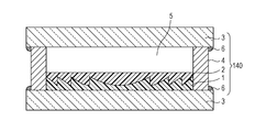
- Fig. 1C is a schematic view showing another embodiment of the multilayer diffractive optical element of the present invention.
- a space 5 for supplying oxygen is provided on the second resin layer 1 shown in Fig. 1A.
- the height (distance between the second resin layer 1 and another transparent substrate 3) of the space for supplying oxygen be in a range of 50 micrometers to 5 mm
- the concentration of oxygen contained in the space be 10 to 100 percent by volume
- the concentration of water contained in the space be 230 g/m 3 or less (relative humidity at 25 degrees Celsius: 10 percent).
- end portions of the space 5 are sealed by a spacer 4 and a sealing agent 6 so as to prevent the entry of moisture from the outside.
- a sealing agent for example, a sealing material OE-6450A/B (Dow Corning Toray Co., Ltd.) may be mentioned.
- a diffractive optical element By using the multilayer diffractive optical element shown in Fig. 1C, a diffractive optical element can be provided in which layers having different refractive-index wavelength dispersions are laminated on a substrate, the diffraction efficiency of specific order (design order) is designed high in the entire region of use wavelength band, and the properties are not changed by visible light or ultraviolet rays.
- Fig. 1D is a schematic view showing another embodiment of the multilayer diffractive optical element of the present invention.
- a space 5 for supplying oxygen is provided on the first resin layer 2 of the multilayer diffractive optical element shown in Fig. 1B.
- the height (distance between the first resin layer 2 and another transparent substrate 3) of the space for supplying oxygen be in a range of 50 micrometers to 5 mm
- the concentration of oxygen contained in the space be 10 to 100 percent by volume
- the concentration of water contained in the space be 230 g/m 3 or less (relative humidity at 25 degrees Celsius: 10 percent).
- end portions of the space 5 are sealed by a spacer 4 and a sealing agent 6 so as to prevent the entry of moisture from the outside.
- a diffractive optical element By using the multilayer diffractive optical element shown in Fig. 1D, a diffractive optical element can be provided in which layers having different refractive-index wavelength dispersions are laminated on a substrate, the diffraction efficiency of specific order (design order) is designed high in the entire region of use wavelength band, and the properties are not changed by visible light or ultraviolet rays.
- a particulate dispersion liquid (average fine particle diameter of indium tin oxide: 20 nm, concentration thereof: 9.96 percent by weight, amount of dispersing agent: 2.19 percent by weight) in which indium tin oxide (ITO) was dispersed in a xylene solvent, and as an ultraviolet curing acrylic resin, 3.72 g of a mixture containing 20 percent by weight of tris(2-acryloxyethyl)isocyanurate, 25 percent by weight of pentaerythritol triacrylate, 40 percent by weight of (dicyclopentenyloxy)ethyl methacrylate, 13 percent by weight of urethane modified polyester-acrylate, and 2 percent by weight of 1-hydroxycyclohexyl phenyl ketone were mixed together.
- ITO indium tin oxide
- This mixed solution was received in an evaporator, and the xylene solvent was removed at an oil bath temperature of 45 degrees Celsius at a final stage and a set pressure of 2 hPa for 15 hours, so that a low refractive index and high dispersion material 11 was prepared.
- the fine particle diameter of the indium tin oxide (ITO) was measured by a laser type fine particle size distribution meter (ELS, manufactured by Otsuka Electronics Co., Ltd.).
- the low refractive index and high dispersion material 11 was fired, and the inorganic solid content thereof was measured.
- the inorganic solid content was 51.2 percent by weight.
- a gas chromatography (5890 series II: manufactured by Hewlett-Packard Development Company) was used for measurement of a residual solvent (xylene), and the content thereof was 0.015 percent by weight.
- a particulate dispersion liquid (average fine particle diameter of zirconium oxide: 10 nm, concentration thereof: 10.11 percent by weight, amount of dispersing agent: 2.27 percent by weight) in which zirconium oxide was dispersed in a toluene solvent, and as an ultraviolet curing acrylic resin, 9.41 g of a mixture containing 20 percent by weight of tris(2-acryloxyethyl)isocyanurate, 25 percent by weight of pentaerythritol triacrylate, 40 percent by weight of (dicyclopentenyloxy)ethyl methacrylate, 13 percent by weight of a urethane modified polyester-acrylate, and 2 percent by weight of 1-hydroxycyclohexyl phenyl ketone were mixed together.
- This mixed solution was received in an evaporator, and the toluene solvent was removed at an oil bath temperature of 45 degrees Celsius at a final stage and a set pressure of 3 hPa for 15 hours, so that a high refractive index and low dispersion material 21 was prepared.
- the fine particle diameter of the zirconium oxide was measured by a laser type fine particle size distribution meter (ELS, manufactured by Otsuka Electronics Co., Ltd.).
- the high refractive index and low dispersion material 21 was fired, and the inorganic solid content thereof was measured.
- the inorganic solid content was 53.7 percent by weight.
- a gas chromatography (5890 series II: manufactured by Hewlett-Packard Development Company) was used for measurement of a residual solvent (toluene), and the content thereof was 0.005 percent by weight or less.
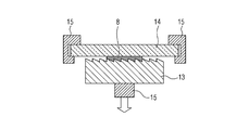
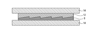
- Figs. 2A to 2C are schematic views each showing a method for forming a sample for refractive-index measurement.
- a spacer 10 having a thickness of 12.5 micrometers and a measurement material 8 to be measured (low refractive index and high dispersion material 11) were arranged on a high refractive index glass 7 (S-TIH11: manufactured by Ohara Inc.) having a thickness of 1 mm.
- a quartz glass 9 having a thickness of 1 mm was further provided on the measurement material 8 with the spacer 10 provided therebetween, so that the measurement material 8 was extended by pressure.
- This measurement material 8 was irradiated with a high pressure mercury lamp (EXECURE250, manufactured by HOYA CANDEO OPTRONICS Corp.) at 20 mW/cm 2 (illumination through a quartz glass) for 1,300 seconds (26 J), so that the measurement material 8 was cured.
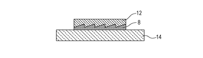
- the quartz glass 9 was peeled off after the curing, and annealing was performed at 80 degrees Celsius for 72 hours. Subsequently, as shown in Fig.
- the quartz glass 9 having a thickness of 1 mm was provided on the measurement material 12 with the spacer 11 provided therebetween, so that the measurement material 12 was extended by pressure to form a sample.
- This measurement material 12 was irradiated with a high pressure mercury lamp (EXECURE250, manufactured by HOYA CANDEO OPTRONICS Corp.) at 20 mW/cm 2 (illumination through a quartz glass) for 1,300 seconds (26 J), so that the measurement material 12 was cured.
- the quartz glass 9 was peeled off after the curing, and annealing was performed at 80 degrees Celsius for 72 hours, so that a sample for refractive index measurement was prepared.
- the structure of the sample for measurement is shown in Fig. 2C.
- the refractive indices of the cured sample at the g line (435.8 nm), the F line (486.1 nm), the e line (546.1 nm), the d line (587.6 nm), and the c line (656.3 nm) were measured from a high refractive index glass 7 side by using a refractometer (KPR-30, manufactured by Shimadzu Corp.). In addition, from the refractive indices thus measured, Abbe's number was calculated.
- Multilayer diffractive optical element Next, after a diffraction optical shape was formed from the low refractive index and high dispersion material 11, the high refractive index and low dispersion material 21 was laminated thereon to form a multilayer diffractive optical element without forming any space therebetween, and the evaluation thereof was then performed.
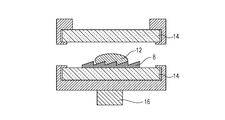
- FIGs. 3A and 3B and Figs. 4A to 4C are schematic views each showing a method for forming a multilayer diffractive optical element for evaluation of diffraction efficiency.
- the measurement material 8 low refractive index and high dispersion material 11
- a flat glass 14 having a thickness of 2 mm was arranged thereon.
- Irradiation was performed using a high pressure mercury lamp (EXECURE250, manufactured by Hoya CANDEO OPTRONICS, Inc.) at 14.2 mW/cm 2 for 211 seconds and at 20 mW/cm 2 for 600 seconds, and annealing was then performed in the air at 80 degrees Celsius for 72 hours, thereby forming a diffraction grating.
- a grating height of the diffraction grating measured after the annealing was 11.7 micrometers, and the pitch thereof was 80 micrometers (Fig. 3B).
- the measurement material 8 formed on the flat glass 14 was set in a molding jig 16 together with the flat glass 14, and subsequently, on the measurement material 8, the measurement material 12 (high refractive index and low dispersion material 21) was dripped (Fig. 4A).
- Another flat glass 14 was placed thereon, and the measurement material 12 was extended by pressure so that the thickness of the resin was larger than the grating height by 30 micrometers, thereby forming a sample (Fig. 4B).
- a high temperature/high humidity test apparatus compact environmental tester IW241, manufactured by Yamato Scientific Co., Ltd.
- the diffraction efficiency of the multilayer diffractive optical element formed from the low refractive index and high dispersion material 11 and the high refractive index and low dispersion material 21 in the entire visible range was 99 percent or more.
- n g to n C each represent the refractive index
- neu d represents Abbe's number
- theta gF represents the relative partial dispersion (secondary dispersion).
- Refractive indices (n g , n F , n e , n d , n C ) (1.6037, 1.5916, 1.5809, 1.5740, 1.5640)
- Refractive indices (n g , n F , n e , n d , n C ) (1.641, 1.633, 1.627, 1.623, 1.619)
- Refractive indices (n g , n F , n e , n d , n C ) (1.6027, 1.5909, 1.5802, 1.5733, 1.5632)
- the change in refractive index from the initial value was -0.0007 to -0.0010.
- Refractive indices (n g , n F , n e , n d , n C ) (1.6416, 1.6336, 1.6271, 1.6237, 1.6196)
- the change in refractive index from the initial value was +0.0003 to +0.0005.
- Refractive indices (n g , n F , n e , n d , n C ) (1.6015, 1.5895, 1.5787, 1.5720, 1.5621)
- the change in refractive index from the initial value was -0.0019 to -0.0022.
- Refractive indices (n g , n F , n e , n d , n C ) (1.6364, 1.6285, 1.6219, 1.6186, 1.6143)
- the change in refractive index from the initial value was -0.0046 to -0.0049.
- Example 1 Unlike the case of Example 1, a space having a height (distance between the measurement material 12 and the quartz glass 9 of Fig. 5) in a range of 50 micrometers to 5 mm for supplying oxygen was provided on the sample for refractive index measurement and the multilayer diffractive optical element, and the surroundings of the space were sealed with a sealing agent so that moisture is not allowed to enter.
- the spacer 10 having a thickness of 12.5 micrometers and the measurement material 8 to be measured were arranged on the high refractive index glass 7 (S-TIH11: manufactured by Ohara Inc.) having a thickness of 1 mm.
- the quartz glass 9 having a thickness of 1 mm was further provided on the measurement material 8 with the spacer 10 provided therebetween, and the measurement material 8 was extended by pressure.
- Irradiation was performed on this measurement material 8 using a high pressure mercury lamp (EXECURE250, manufactured by Hoya CANDEO OPTRONICS, Inc.) at 20 mW/cm 2 (illumination through a quartz glass) for 1,300 seconds (26 J), so that the measurement material 8 was cured. After the curing, the quartz glass 9 was peeled off, and annealing was performed at 80 degrees Celsius for 72 hours. Subsequently, as shown in Fig.
- EXECURE250 manufactured by Hoya CANDEO OPTRONICS, Inc.
- the quartz glass 9 having a thickness of 1 mm was provided on the measurement material 12 with the spacer 11 provided therebetween, so that the measurement material 12 was extended by pressure to form a sample.
- This measurement material 12 was irradiated with a high pressure mercury lamp (EXECURE250, manufactured by HOYA CANDEO OPTRONICS Corp.) at 20 mW/cm 2 (illumination through a quartz glass) for 1,300 seconds (26 J), so that the measurement material 12 was cured.
- the quartz glass 9 was peeled off after the curing, and annealing was performed at 80 degrees Celsius for 72 hours.
- a sealing agent 18 (sealing material for LED, OE-6450 A/B) was arranged and was then cured at 80 degrees Celsius for 24 hours, and a sample for refractive index measurement having a space 19 of 25 micrometers to 5 mm for supplying oxygen was formed.
- Fig. 5 The structure of the sample for refractive index measurement is shown Fig. 5.
- Sample for refractive index measurement 12-0 was a sample for refractive index measurement formed using the 75-micrometer spacer 17 to arrange a space of 25 micrometers for supplying oxygen.
- Sample for refractive index measurement 12-1 was a sample for refractive index measurement formed using the 100-micrometer spacer 17 to arrange a space of 50 micrometers for supplying oxygen.
- Sample for refractive index measurement 12-2 was a sample for refractive index measurement formed using the 150-micrometer spacer 17 to arrange a space of 100 micrometers for supplying oxygen.
- Sample for refractive index measurement 12-3 was a sample for refractive index measurement formed using the 500-micrometer spacer 17 to arrange a space of 450 micrometers for supplying oxygen.
- Sample for refractive index measurement 12-4 was a sample for refractive index measurement formed using the 1-mm spacer 17 to arrange a space of 950 micrometers for supplying oxygen.
- Sample for refractive index measurement 12-5 was a sample for refractive index measurement formed using the 5-mm spacer 17 to arrange a space of 5 mm for supplying oxygen.
- the refractive indices of the cured sample at the g line (435.8 nm), the F line (486.1 nm), the e line (546.1 nm), the d line (587.6 nm), and the c line (656.3 nm) were measured from a high refractive index glass 7 side by using a refractometer (KPR-30, manufactured by Shimadzu Corp.). In addition, from the refractive indices thus measured, Abbe's number was calculated.
- the measurement material 8 (low refractive index and high dispersion material 11) was arranged, and the glass substrate 14 having a thickness of 2 mm was arranged thereon. Irradiation was performed using a high pressure mercury lamp (EXECURE250, manufactured by Hoya CANDEO OPTRONICS, Inc.) at 14.2 mW/cm 2 for 211 seconds and at 20 mW/cm 2 for 600 seconds, and annealing was then performed in the air at 80 degrees Celsius for 72 hours, thereby forming a diffraction grating.
- EXECURE250 manufactured by Hoya CANDEO OPTRONICS, Inc.
- a grating height of the diffraction grating measured after the annealing was 11.7 micrometers, and the pitch thereof was 80 micrometers.
- the measurement material 8 formed on the flat glass 14 was set in the molding jig 16 together with the flat glass 14, and subsequently, on the measurement material 8, the measurement material 12 (high refractive index and low dispersion material 21) was dripped (Fig. 4A).
- the another flat glass 14 was placed thereon, and the measurement material 12 was extended by pressure so that the thickness of the resin was larger than the grating height by 30 micrometers, thereby forming the sample (Fig. 4B).
- the sealing agent 18 (sealing material for LED, OE-6450 A/B) was arranged and was then cured at 80 degrees Celsius for 24 hours, so that a multilayer diffractive optical element having a space 19 of 50 micrometers to 5 mm for supplying oxygen was formed.
- the structure of the multilayer optical element is shown in Fig. 6.
- Multilayer diffractive optical element 12-0 was a multilayer diffractive optical element formed using the 75-micrometer spacer 17 to have a space of 25 micrometers for supplying oxygen.
- Multilayer diffractive optical element 12-1 was a multilayer diffractive optical element formed using the 100-micrometer spacer 17 to have a space of 50 micrometers for supplying oxygen.
- Multilayer diffractive optical element 12-2 was a multilayer diffractive optical element formed using the 150-micrometer spacer 17 to have a space of 100 micrometers for supplying oxygen.
- Multilayer diffractive optical element 12-3 was a multilayer diffractive optical element formed using the 500-micrometer spacer 17 to have a space of 450 micrometers for supplying oxygen.
- Multilayer diffractive optical element 12-4 was a multilayer diffractive optical element formed using the 1-mm spacer 17 to have a space of 950 micrometers for supplying oxygen.
- Multilayer diffractive optical element 12-5 was a multilayer diffractive optical element formed using the 5-mm spacer 17 to have a space of 5 mm for supplying oxygen.
- the diffraction efficiency of each of the multilayer diffractive optical elements 12-0, 12-1, 12-2, 12-3, 12-4, and 12-5 in the entire visible range was 99 percent or more.
- the delta n was plus or minus 0.0003, and there was no significant difference.
- Refractive indices (n g , n F , n e , n d , n C ) (1.641, 1.633, 1.627, 1.623, 1.619)
- the delta n was plus or minus 0.0003, and there was no significant difference.
- the diffraction efficiency of the multilayer diffractive optical element 12-0 in the entire visible range was 98% or more and was changed from the initial value by 1 to 2 percent.
- the spacer 10 having a thickness of 12.5 micrometers and the measurement material 8 to be measured were arranged on the high refractive index glass 7 (S-TIH11: manufactured by Hoya Corp.) having a thickness of 1 mm.
- the quartz glass 9 having a thickness of 1 mm was further provided on the measurement material 8 with the spacer 10 interposed therebetween, and the measurement material 8 was extended by pressure.
- Irradiation was performed on this measurement material 8 using a high pressure mercury lamp (EXECURE250, manufactured by Hoya CANDEO OPTRONICS, Inc.) at 20 mW/cm 2 (illumination through a quartz glass) for 1,300 seconds (26 J), so that the measurement material 8 was cured. After the curing, the quartz glass 9 was peeled off, and annealing was performed at 80 degrees Celsius for 72 hours. Subsequently, as shown in Fig.
- EXECURE250 manufactured by Hoya CANDEO OPTRONICS, Inc.
- the quartz glass 9 having a thickness of 1 mm was provided on the measurement material 12 with the spacer 11 interposed therebetween, and the measurement material 12 was then extended by pressure to form a sample.
- This measurement material 12 was irradiated with a high pressure mercury lamp (EXECURE250, manufactured by HOYA CANDEO OPTRONICS Corp.) at 20 mW/cm 2 (illumination through a quartz glass) for 1,300 seconds (26 J), so that the measurement material 12 was cured.
- a high pressure mercury lamp EXECURE250, manufactured by HOYA CANDEO OPTRONICS Corp.
- the quartz glass 9 was not peeled off, and annealing was performed at 80 degrees Celsius for 72 hours, so that the sample for measurement was obtained.
- the refractive indices of the cured sample at the g line (435.8 nm), the F line (486.1 nm), the e line (546.1 nm), the d line (587.6 nm), and the c line (656.3 nm) were measured from a high refractive index glass 7 side by using a refractometer (KPR-30, manufactured by Shimadzu Corp.). In addition, from the refractive indices thus measured, Abbe's number was calculated.
- Multilayer diffractive optical element Next, after a diffraction optical shape was formed from the low refractive index and high dispersion material 11, the high refractive index and low dispersion material 21 was laminated thereon to form a multilayer diffractive optical element, and the evaluation thereof was then performed.
- the measurement material 8 (low refractive index and high dispersion material 11) was arranged, and the glass substrate 14 having a thickness of 2 mm was arranged thereon. Irradiation was performed using a high pressure mercury lamp (EXECURE250, manufactured by Hoya CANDEO OPTRONICS, Inc.) at 14.2 mW/cm 2 for 211 seconds and at 20 mW/cm 2 for 600 seconds, and annealing was then performed in the air at 80 degrees Celsius for 72 hours, thereby forming a diffraction grating.
- EXECURE250 manufactured by Hoya CANDEO OPTRONICS, Inc.
- a grating height of the diffraction grating measured after the annealing was 12 micrometers, and the pitch thereof was 80 micrometers.
- the grating height of the diffraction grating was optimized based on the measurement result of the refractive index.
- the measurement material 8 formed on the flat glass 14 was set in the molding jig 16 together with the flat glass 14, and subsequently, on the measurement material 8, the measurement material 12 (high refractive index and low dispersion material 21) was dripped (Fig. 4A).
- the another flat glass 14 was placed thereon, and the measurement material 12 was extended by pressure so that the thickness of the resin was larger than the grating height by 30 micrometers, thereby forming the sample (Fig. 4B).
- the diffraction efficiency of the multilayer diffractive optical element formed from the low refractive index and high dispersion material 11 and the high refractive index and low dispersion material 21 in the entire visible range was 99 percent or more.
- Refractive indices (n g , n F , n e , n d , n C ) (1.6009, 1.5888, 1.5776, 1.5704, 1.5596)
- the delta n from Example 1 was -0.0028 to -0.0044.
- Refractive indices (n g , n F , n e , n d , n C ) (1.6364, 1.6285, 1.6220, 1.6186, 1.6145)
- the delta n from Example 1 was -0.0045 to -0.0048.
- the change in refractive index from the initial value was -0.0011 to -0.0025.
- Refractive indices (n g , n F , n e , n d , n C ) (1.6365, 1.6286, 1.6220, 1.6187, 1.6146)
- the diffraction efficiency of the multilayer diffractive optical element formed from the low refractive index and high dispersion material 11 and the high refractive index and low dispersion material 21 in the entire visible range was 99 percent or more and was not so much changed from the initial value.
- Refractive indices (n g , n F , n e , n d , n C ) (1.6009, 1.5889, 1.5777, 1.5704, 1.5597)
- the change in refractive index from the initial value was 0.0000 to +0.0001.
- Refractive indices (n g , n F , n e , n d , n C ) (1.6364, 1.6285, 1.6220, 1.6186, 1.6145)
- Comparative Example 1 the resin composition containing ITO fine particles and a monomer is cured by irradiation of ultraviolet rays, and the low refractive index and high dispersion material 11 (first resin layer) and the high refractive index and low dispersion material 21 (second resin layer) are sealed with the quartz glass 9 and the flat glass 14, so that the multilayer diffractive optical element which blocks the supply of oxygen is formed. Under the conditions in which the supply of oxygen is blocked, radicals are generated by a photochemical reaction of the resin using ultraviolet rays.
- ITO Since the radicals thus generated are trapped by the ITO fine particles, ITO is placed in a reduced state by the radicals, and the optical properties, such as the refractive index and the absorption of light, are changed, so that the performance of the multilayer diffractive optical element is influenced.
- the space for supplying oxygen is provided on the high refractive index and low dispersion material 21 (second resin layer). Therefore, since the second resin layer incorporates oxygen in the air and brings oxygen into contact with the ITO material of the first resin layer, the radicals trapped by the ITO fine particles are eliminated by oxygen, and reduced ITO is returned to the original state by oxidation thereof. Accordingly, the change in optical properties, such as the refractive index and the absorption of light, can be decreased in the light resistance test and the like.
- the present invention is able to provide a diffractive optical element which prevents the change in properties caused by visible light or ultraviolet rays and moisture absorption.
- the present invention can be applied to an optical element, a diffractive optical element, a multilayer diffractive optical element, and an optical system, in particular, an imaging optical system, such as a camera and a video camera.
Landscapes
- Engineering & Computer Science (AREA)
- Physics & Mathematics (AREA)
- Health & Medical Sciences (AREA)
- Manufacturing & Machinery (AREA)
- Ophthalmology & Optometry (AREA)
- Mechanical Engineering (AREA)
- General Physics & Mathematics (AREA)
- Optics & Photonics (AREA)
- Diffracting Gratings Or Hologram Optical Elements (AREA)
- Polymerisation Methods In General (AREA)
Abstract
L'invention porte sur un élément optique à diffraction multicouche, dans lequel élément une première couche de résine constituée par une composition de résine contenant de fines particules d'une substance conductrice transparente et ayant une forme de réseau de diffraction, et une seconde couche de résine utilisée pour la transmission d'oxygène et ayant au moins une surface de forme de réseau de diffraction sont stratifiées sur un substrat transparent, de telle sorte que la forme de réseau de diffraction de la première couche de résine et celle de la seconde couche de résine se font face, et dans lequel un espace pour délivrer de l'oxygène est disposé sur la seconde couche de résine. Par la structure telle que décrite ci-dessus, un état de rendement de diffraction élevé peut être maintenu dans la totalité de la plage visible sans aucun changement au cours du temps.
Applications Claiming Priority (2)
| Application Number | Priority Date | Filing Date | Title |
|---|---|---|---|
| JP2011086139A JP5863265B2 (ja) | 2011-04-08 | 2011-04-08 | 光学素子および多層回折光学素子 |
| JP2011-086139 | 2011-04-08 |
Publications (1)
| Publication Number | Publication Date |
|---|---|
| WO2012137452A1 true WO2012137452A1 (fr) | 2012-10-11 |
Family
ID=46025840
Family Applications (1)
| Application Number | Title | Priority Date | Filing Date |
|---|---|---|---|
| PCT/JP2012/002230 Ceased WO2012137452A1 (fr) | 2011-04-08 | 2012-03-30 | Élément optique et élément optique à diffraction multicouche |
Country Status (2)
| Country | Link |
|---|---|
| JP (1) | JP5863265B2 (fr) |
| WO (1) | WO2012137452A1 (fr) |
Cited By (2)
| Publication number | Priority date | Publication date | Assignee | Title |
|---|---|---|---|---|
| EP3259625A1 (fr) * | 2015-02-16 | 2017-12-27 | Apple Inc. | Scellement hermétique à basse température pour des empilements d'éléments optiques diffractifs |
| US11603457B2 (en) | 2017-09-05 | 2023-03-14 | Fujifilm Corporation | Curable composition, cured product, and lens unit |
Families Citing this family (1)
| Publication number | Priority date | Publication date | Assignee | Title |
|---|---|---|---|---|
| JPWO2013175801A1 (ja) * | 2012-05-25 | 2016-01-12 | パナソニックIpマネジメント株式会社 | 回折光学素子およびその製造方法 |
Citations (11)
| Publication number | Priority date | Publication date | Assignee | Title |
|---|---|---|---|---|
| JPS4841708A (fr) | 1971-09-25 | 1973-06-18 | ||
| JPS4864183A (fr) | 1971-12-09 | 1973-09-05 | ||
| JPS4943191A (fr) | 1972-09-02 | 1974-04-23 | ||
| JPS506034A (fr) | 1972-11-28 | 1975-01-22 | ||
| JPS5137193A (fr) | 1974-09-25 | 1976-03-29 | Toyo Boseki | |
| JPS5230490A (en) | 1975-09-03 | 1977-03-08 | Denki Kagaku Keiki Co Ltd | Gas concentration measuring electrode stable in air |
| EP1394574A2 (fr) * | 2002-08-30 | 2004-03-03 | Canon Kabushiki Kaisha | Materiél optique, élément optique et systéme optique et élément de diffraction laminé les utilisant |
| EP1947488A1 (fr) * | 2007-01-22 | 2008-07-23 | Canon Kabushiki Kaisha | Élément optique à diffraction stratifiée |
| JP2008203821A (ja) | 2007-01-22 | 2008-09-04 | Canon Inc | 積層型回折光学素子 |
| US20090141354A1 (en) * | 2007-12-03 | 2009-06-04 | Canon Kabushiki Kaisha | Diffractive optical element and optical system including the same |
| JP2011086139A (ja) | 2009-10-16 | 2011-04-28 | Honda Motor Co Ltd | 車両の衝突を回避するための装置 |
Family Cites Families (2)
| Publication number | Priority date | Publication date | Assignee | Title |
|---|---|---|---|---|
| JP4958144B2 (ja) * | 2005-06-08 | 2012-06-20 | 三菱マテリアル電子化成株式会社 | 透明導電膜形成用組成物、透明導電膜及びディスプレイ |
| JP5287080B2 (ja) * | 2007-10-18 | 2013-09-11 | 日油株式会社 | プラズマディスプレイパネル用ハードコートフィルム及びプラズマディスプレイパネル |
-
2011
- 2011-04-08 JP JP2011086139A patent/JP5863265B2/ja not_active Expired - Fee Related
-
2012
- 2012-03-30 WO PCT/JP2012/002230 patent/WO2012137452A1/fr not_active Ceased
Patent Citations (11)
| Publication number | Priority date | Publication date | Assignee | Title |
|---|---|---|---|---|
| JPS4841708A (fr) | 1971-09-25 | 1973-06-18 | ||
| JPS4864183A (fr) | 1971-12-09 | 1973-09-05 | ||
| JPS4943191A (fr) | 1972-09-02 | 1974-04-23 | ||
| JPS506034A (fr) | 1972-11-28 | 1975-01-22 | ||
| JPS5137193A (fr) | 1974-09-25 | 1976-03-29 | Toyo Boseki | |
| JPS5230490A (en) | 1975-09-03 | 1977-03-08 | Denki Kagaku Keiki Co Ltd | Gas concentration measuring electrode stable in air |
| EP1394574A2 (fr) * | 2002-08-30 | 2004-03-03 | Canon Kabushiki Kaisha | Materiél optique, élément optique et systéme optique et élément de diffraction laminé les utilisant |
| EP1947488A1 (fr) * | 2007-01-22 | 2008-07-23 | Canon Kabushiki Kaisha | Élément optique à diffraction stratifiée |
| JP2008203821A (ja) | 2007-01-22 | 2008-09-04 | Canon Inc | 積層型回折光学素子 |
| US20090141354A1 (en) * | 2007-12-03 | 2009-06-04 | Canon Kabushiki Kaisha | Diffractive optical element and optical system including the same |
| JP2011086139A (ja) | 2009-10-16 | 2011-04-28 | Honda Motor Co Ltd | 車両の衝突を回避するための装置 |
Cited By (3)
| Publication number | Priority date | Publication date | Assignee | Title |
|---|---|---|---|---|
| EP3259625A1 (fr) * | 2015-02-16 | 2017-12-27 | Apple Inc. | Scellement hermétique à basse température pour des empilements d'éléments optiques diffractifs |
| US10732428B2 (en) | 2015-02-16 | 2020-08-04 | Apple Inc. | Low-temperature hermetic sealing for diffractive optical element stacks |
| US11603457B2 (en) | 2017-09-05 | 2023-03-14 | Fujifilm Corporation | Curable composition, cured product, and lens unit |
Also Published As
| Publication number | Publication date |
|---|---|
| JP2012220711A (ja) | 2012-11-12 |
| JP5863265B2 (ja) | 2016-02-16 |
Similar Documents
| Publication | Publication Date | Title |
|---|---|---|
| US20210223437A1 (en) | Optical element and method for manufacturing the same | |
| EP2081056B1 (fr) | Elément optique diffractif stratifié et composition de résine associée | |
| US9696469B2 (en) | Multilayer diffractive optical element | |
| EP2565227A1 (fr) | Matériau composite organique-inorganique, élément optique et élément optique à diffraction multicouche | |
| EP3570076B1 (fr) | Produit durci, et élément optique, élément optique diffractif, appareil optique et dispositif d'imagerie utilisant le produit durci | |
| JP5773579B2 (ja) | 多層型回折光学素子 | |
| WO2018212051A1 (fr) | Film antireflet anti-éblouissement ainsi que procédé de fabrication de celui-ci, plaque polarisante, dispositif d'affichage d'image, et dispositif d'affichage de type auto-luminescent | |
| WO2012137452A1 (fr) | Élément optique et élément optique à diffraction multicouche | |
| JP2010169708A (ja) | 複合型光学素子 | |
| EP2484721A1 (fr) | Composition de résine composite organique-inorganique, matériau de résine composite organique-inorganique, élément optique et élément optique à diffraction empilée | |
| US11156750B2 (en) | Laminated diffractive optical element and method for manufacturing laminated diffractive optical element | |
| JP7327979B2 (ja) | 硬化物、硬化物を用いた光学素子、回折光学素子、光学機器および撮像装置 | |
| US12601864B2 (en) | Optical element, optical equipment, and imaging apparatus | |
| EP2243622A2 (fr) | Procédé de production de pièce optique | |
| JP2006342254A (ja) | 光硬化型樹脂組成物の製造方法 | |
| JP2021085950A (ja) | 回折光学素子、光学機器および撮像装置 |
Legal Events
| Date | Code | Title | Description |
|---|---|---|---|
| 121 | Ep: the epo has been informed by wipo that ep was designated in this application |
Ref document number: 12718410 Country of ref document: EP Kind code of ref document: A1 |
|
| NENP | Non-entry into the national phase |
Ref country code: DE |
|
| 122 | Ep: pct application non-entry in european phase |
Ref document number: 12718410 Country of ref document: EP Kind code of ref document: A1 |