WO2012137544A1 - Capteur magnétique - Google Patents
Capteur magnétique Download PDFInfo
- Publication number
- WO2012137544A1 WO2012137544A1 PCT/JP2012/053746 JP2012053746W WO2012137544A1 WO 2012137544 A1 WO2012137544 A1 WO 2012137544A1 JP 2012053746 W JP2012053746 W JP 2012053746W WO 2012137544 A1 WO2012137544 A1 WO 2012137544A1
- Authority
- WO
- WIPO (PCT)
- Prior art keywords
- magnetoresistive element
- magnetic sensor
- magnet
- magnets
- magnetoresistive
- Prior art date
- Legal status (The legal status is an assumption and is not a legal conclusion. Google has not performed a legal analysis and makes no representation as to the accuracy of the status listed.)
- Ceased
Links
Images


Classifications
-
- G—PHYSICS
- G01—MEASURING; TESTING
- G01R—MEASURING ELECTRIC VARIABLES; MEASURING MAGNETIC VARIABLES
- G01R33/00—Arrangements or instruments for measuring magnetic variables
- G01R33/0047—Housings or packaging of magnetic sensors ; Holders
-
- G—PHYSICS
- G01—MEASURING; TESTING
- G01R—MEASURING ELECTRIC VARIABLES; MEASURING MAGNETIC VARIABLES
- G01R33/00—Arrangements or instruments for measuring magnetic variables
- G01R33/02—Measuring direction or magnitude of magnetic fields or magnetic flux
- G01R33/06—Measuring direction or magnitude of magnetic fields or magnetic flux using galvano-magnetic devices
- G01R33/09—Magnetoresistive devices
- G01R33/091—Constructional adaptation of the sensor to specific applications
-
- H—ELECTRICITY
- H10—SEMICONDUCTOR DEVICES; ELECTRIC SOLID-STATE DEVICES NOT OTHERWISE PROVIDED FOR
- H10N—ELECTRIC SOLID-STATE DEVICES NOT OTHERWISE PROVIDED FOR
- H10N50/00—Galvanomagnetic devices
- H10N50/10—Magnetoresistive devices
-
- H—ELECTRICITY
- H10—SEMICONDUCTOR DEVICES; ELECTRIC SOLID-STATE DEVICES NOT OTHERWISE PROVIDED FOR
- H10N—ELECTRIC SOLID-STATE DEVICES NOT OTHERWISE PROVIDED FOR
- H10N50/00—Galvanomagnetic devices
- H10N50/80—Constructional details
Definitions
- the present invention relates to a long magnetic sensor that detects a magnetic pattern printed on, for example, banknotes.
- Patent Document 1 is disclosed as a magnetic sensor for discriminating an object to be detected such as a bill or a security printed with a predetermined pattern with magnetic ink or the like.
- the vibration in the fundamental wave mode is a bending vibration in which both ends of the long magnetic sensor are fixed ends.
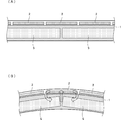
- FIG. 1A shows a state in which no bending stress is applied to the long magnetic sensor.
- a plurality of magnetoresistive elements 2, a plurality of magnets 5 that apply a magnetic field to the magnetic sensing portions of the plurality of magnetoresistive elements 2, and a case 1 that holds the magnetoresistive elements 2 and the magnets 5 are provided. Yes.
- the plurality of magnets 5 and the plurality of magnets 5 are arranged such that the position of the opposing portion between the magnets 5 of the plurality of magnets 5 is the center position of a certain magnetoresistive element 2 of the plurality of magnetoresistive elements 2.
- a resistance element 2 is arranged.
- FIG. 1B is a partial sectional view exaggeratingly showing a state in which bending stress is applied to the long magnetic sensor.
- the case 1 is a resin molded from a resin mold
- the magnetoresistive element 2 and the magnet 5 are softer than the case 1. For this reason, when bending stress is applied to the long magnetic sensor, stress distortion occurs in the magnetoresistive element 2 corresponding to the facing portion (magnet joint position) between the magnet 5 and the magnet 5.
- the magnetoresistive element 2 is made of an n-InSb material, InAs material, GaAs material, Ge material, or Si material having high electron mobility. Such a magnetoresistive element material has a piezoresistive effect. Therefore, when stress strain occurs in the magnetoresistive element 2, a signal due to the piezoresistive effect is superimposed, and this acts as noise (piezonoise).
- the bending stress applied to the magnetoresistive element 2 can be reduced, but not only the distance accuracy between the magnetic sensor and the object to be detected is lowered, but also the amplitude of the bending vibration is increased. End up. Since the detection sensitivity of the magnetic body is affected by the square of the distance between the magnetic sensing portion of each magnetoresistive element of the magnetic sensor and the magnetic body to be detected, a flexible material cannot be used for the case of the magnetic sensor.
- the stress strain applied to the magnetoresistive element 2 is reduced.
- the opposing portion of the magnetoresistive element 2 and the magnetoresistive element 2 naturally has no magnetic sensitive part (disconnected)
- the detection sensitivity of the magnetic material tends to decrease
- the magnet 5 and the magnet 5 Since the opposing part has a tendency that the detection sensitivity of the magnetic material is lowered due to the small magnetic flux density, both sensitivity reduction factors overlap. Therefore, it is difficult to adopt a structure in which the magnet facing portion overlaps the magnetoresistive element facing portion.
- the present invention has been made in view of the above-described problems, and an object thereof is to provide a magnetic sensor that solves the above-described piezo noise problem caused by bending vibration accompanying the increase in length of the magnetic sensor.
- the magnetic sensor of the present invention includes a plurality of magnetoresistive elements, a plurality of magnets, and a case for holding the plurality of magnetoresistive elements and the plurality of magnets, and the case includes the plurality of magnetoresistive elements in series. And a magnet holding part for holding the plurality of magnets in series so as to apply a magnetic field to the magnetoresistive element placed on the magnetoresistive element placing part.
- the plurality of magnets and the plurality of magnetoresistive elements include a magnet facing portion, which is a facing portion between the magnets of the plurality of magnets, and a magnetoresistive element and a magnetoresistive element of the plurality of magnetoresistive elements. Are arranged so as to correspond to positions other than the opposite part of The magnetoresistive element is bonded to the case through an adhesive layer at a part of the surface of the magnetoresistive element facing the case.
- a magnetic sensor in which piezo noise associated therewith is reduced even when bending vibration occurs in the magnetic sensor can be configured.
- FIG. 1A is a cross-sectional view of a conventional general long type magnetic sensor in a state where no bending stress is applied.
- FIG. 1B is a partial cross-sectional view in a state where bending stress is applied to the long magnetic sensor.
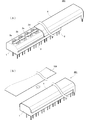
- 2A is an external perspective view in the middle of attaching the cover of the long magnetic sensor 201 according to the first embodiment
- FIG. 2B is an external perspective view in a state in which the cover is attached.
- FIG. 3 is a front view showing a structure in which the magnetic sensor 201 is incorporated into an installation destination device.
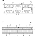
- FIG. 4A is a partial plan view of the magnetic sensor 201 according to the first embodiment with the cover removed.
- FIG. 4B is a partial view of the central longitudinal cross section of the magnetic sensor 201 in the longitudinal direction.
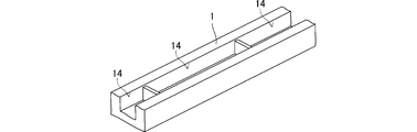
- FIG. 5 is a partial perspective view of the case 1 as viewed from the magnet holding portion 14 side.
- FIG. 6 shows a comparative example of piezo noise generated between the conventional magnetic sensor and the magnetic sensor 201 according to the first embodiment of the present invention.
- FIG. 7A is a partial plan view of the magnetic sensor 202 of the second embodiment with the cover removed.
- FIG. 7B is a partial view of the central longitudinal cross section of the magnetic sensor 202 in the longitudinal direction.
- FIG. 8A is a partial plan view of the magnetic sensor 203 according to the third embodiment with the cover removed.
- FIG. 8B is a partial view of a central longitudinal section in the longitudinal direction of the magnetic sensor 203.
- FIG. 2A is an external perspective view in the middle of attaching the cover of the long magnetic sensor 201 according to the first embodiment
- FIG. 2B is an external perspective view in a state in which the cover is attached.
- the case 1 made of synthetic resin has magnetoresistive elements 2a, 2b, 2c, 2d.
- a terminal pin 6 that conducts to the plurality of magnetoresistive elements 2a, 2b, 2c, 2d,.
- Claw engaging grooves 3 are provided on both sides of the case 1 along the longitudinal direction.
- the cover 4 made of metal is provided with a cover fixing claw portion that engages with the claw portion engagement groove 3 of the case. As shown, a cover 4 is covered on top of the case 1.
- the object to be detected 100 is conveyed in a direction substantially perpendicular to the longitudinal direction of the long magnetic sensor 201 as indicated by an arrow in the figure.
- FIG. 3 is a front view showing a structure in which the magnetic sensor 201 is incorporated into an installation destination device.
- the magnetic sensor 201 is mounted on the circuit board 110 via the terminal pins 6.
- the circuit board 110 is held by a holder 120, and the holder 120 is fixed to a frame or the like of an installation destination device.
- FIG. 4A is a partial plan view of the magnetic sensor 201 of the first embodiment. However, it is shown with the cover removed.
- FIG. 4B is a partial view of the central longitudinal cross section of the magnetic sensor 201 in the longitudinal direction.
- FIG. 5 is a partial perspective view of the case 1 as viewed from the magnet holding portion 14 side.
- the magnet holding part 14 is a recess formed in the lower part of the case 1, and the magnet 5 is accommodated in the magnet holding part 14.
- the case 1 is resin-molded.
- a plurality of magnetoresistive element mounting portions 13i, 13j, 13k and the like are formed on the upper portion of the case 1.
- Magnets 5 are housed in a plurality of magnet holders 14 formed in the lower part of case 1.
- the magnet 5 is filled with a filler 8 such as an epoxy resin so that the magnet 5 is embedded in the magnet holding portion 14.
- the magnetoresistive elements 2i, 2j, 2k and the like are bonded to the lower surfaces of the magnetoresistive element mounting portions 13i, 13j, 13k and the like via the adhesive layer 7.
- a part of the lower surface of the magnetoresistive element 2j is joined by an adhesive layer 7 to the magnetoresistive element mounting portion 13j corresponding to the position of the facing portion between the magnet 5 and the magnet 5.
- Nearly the entire lower surface of the magnetoresistive elements 2i, 2k is joined by an adhesive layer 7 to the magnetoresistive element mounting portions 13i, 13k, etc. that do not correspond to the positions of the opposing portions of the magnets 5 and 5.
- the magnetoresistive elements 2i, 2j, 2k, etc. are bonded to the magnetoresistive element mounting portion on the opposite side of the magnetosensitive element so that the magnetosensitive part is on the upper surface side.
- the electrode pad of the magnetoresistive element is joined to the inner lead of the lead frame, and the outer lead of the lead frame is thermocompression bonded to the terminal pin 6, but in FIG. Illustration of these leads is omitted.
- the magnetoresistive element that is not at the position of the facing portion between the magnet 5 and the magnet 5 and the height of the magnetosensitive element 2j joined to the magnetoresistive element mounting portion 13j corresponding to the facing portion between the magnet 5 and the magnet 5
- the thickness of the adhesive layer 7 is determined so that the heights of the magnetically sensitive portions such as the magnetoresistive elements 2i and 2k joined to the placement portions 13i and 13k are uniform. For example, when the adhesive is applied to the magnetoresistive element mounting portion with a dispenser or the like, the viscosity of the adhesive and the coating amount are determined, and the magnetoresistive element is mounted on the magnetoresistive element mounting portion.
- the spread area of the adhesive on the lower surface of the magnetoresistive element and the thickness of the adhesive layer are determined. Furthermore, the spread amount of the adhesive layer and the thickness of the adhesive layer may be adjusted by the pressing force of the magnetoresistive element on the magnetoresistive element mounting portion.
- the magnetoresistive element 2j joined to the magnetoresistive element mounting portion 13j of the case 1 corresponding to the position of the facing portion between the magnet 5 and the magnet 5 is a part of the lower surface of the magnetoresistive element mounting portion 13j. 1B, even when bending stress as shown in FIG. 1B is applied to the magnetic sensor 201, the bending moment to the magnetoresistive element 2j is reduced. That is, the flat state is maintained with almost no influence of bending at the position of the facing portion between the magnet 5 and the magnet 5 of the case 1. This suppresses the generation of piezo noise.
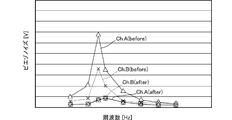
- FIG. 6 shows a comparative example of piezo noise generated between the conventional magnetic sensor and the magnetic sensor 201 according to the first embodiment of the present invention.
- Ch.A (before) is piezo noise generated in the channel A of the conventional magnetic sensor
- Ch.B (before) is piezo noise generated in the channel B of the conventional magnetic sensor.
- Ch.A (after) is piezo noise generated in the channel A of the magnetic sensor 201 of the first embodiment
- Ch.B (after) is piezo noise generated in the channel B of the magnetic sensor 201 of the first embodiment. is there.
- the channel A corresponds to the sixth magnetoresistive element corresponding to the position of the opposing portion of the magnet 5 among the 18 channels (18 magnetoresistive elements) in total.
- the channel B corresponds to the eleventh magnetoresistive element corresponding to the position of another facing portion between the magnet 5 and the magnet 5.
- the horizontal axis represents frequency and the vertical axis represents piezo noise voltage. Both are relative value scales. As shown in FIG. 6, since a mountain shape in which piezo noise rises at a predetermined frequency is drawn, it can be seen that bending vibration is generated at the resonance frequency, and large piezo noise is generated at this resonance frequency. Compared to the magnetic sensor having the conventional structure, the piezo noise can be reduced to about 1/6 or less in the magnetic sensor 201 of the first embodiment.
- FIG. 7A is a partial plan view of the magnetic sensor 202 of the second embodiment. However, it is shown with the cover removed.
- FIG. 7B is a partial view of the central longitudinal cross section of the magnetic sensor 202 in the longitudinal direction.
- Case 1 is resin molded.
- a plurality of magnetoresistive element mounting portions 13i, 13j, 13k and the like are formed on the upper portion of the case 1.
- the lower surfaces of these magnetoresistive element mounting portions 13i, 13j, 13k and the like are magnetoresistive element facing surfaces.
- magnet holders 14 that store a plurality of magnets 5 are formed in the lower part of the case 1, and the magnets 5 are stored in these magnet holders 14, respectively.
- the periphery of the magnet 5 is filled with a filler 8 such as an epoxy resin.
- an adhesive layer 9 for the magnetoresistive element 2j is an adhesive layer 9 for the magnetoresistive element 2j.
- an adhesive in which beads defining the thickness of the adhesive layer are mixed is applied to the magnetoresistive element placement portion 13j of the case 1 corresponding to the position of the facing portion between the magnet 5 and the magnet 5. is doing.
- the thickness of the adhesive layer that joins the magnetoresistive element 2j to the magnetoresistive element mounting portion 13j is relatively small, the thickness of the adhesive layer can be controlled only with a normal adhesive. May be difficult.
- the beads for example, silica beads having a particle diameter of 150 ⁇ m to 200 ⁇ m can be used.
- a mixture of the beads with a Si-based adhesive at a certain ratio is used.
- the thickness of the adhesive layer 9 is defined to be approximately equal to the particle size of the beads.
- the thickness of the adhesive layer such as the magnetoresistive elements 2i and 2k on the magnetoresistive element mounting portions 13i and 13k that are not located at the position where the magnet 5 and the magnet 5 face each other is adjusted by, for example, the amount of adhesive applied.
- the thickness of the adhesive layer of the magnetoresistive element 2j on the magnetoresistive element mounting portion 13j corresponding to the position of the facing portion between the magnet 5 and the magnet 5 may be adjusted by the particle size of the beads to be mixed. In this way, the height of the magnetic sensing part of each magnetoresistive element can be made uniform.
- the adhesive applied to the magnetoresistive element mounting portions 13i, 13k, etc. which is not located at the position where the magnet 5 and the magnet 5 face each other, may be an adhesive mixed with beads defining the thickness of the adhesive layer. Good. Further, the particle size and ratio of the beads to be mixed may be different between the adhesive that limits the application range and the adhesive that is applied to the entire surface.
- the piezo noise reduction effect of the magnetic sensor 202 of the second embodiment is substantially the same as that of the magnetic sensor 201 of the first embodiment.
- FIG. 8A is a partial plan view of the magnetic sensor 203 of the third embodiment. However, it is shown with the cover removed.
- FIG. 8B is a partial view of a central longitudinal section in the longitudinal direction of the magnetic sensor 203.
- the difference from the first and second embodiments is a configuration for increasing the thickness of the adhesive layer provided on the magnetoresistive element mounting portion 13j of the case 1 corresponding to the position of the facing portion between the magnet 5 and the magnet 5. is there. That is, the engraved portion 12 is formed on almost the entire surface of the magnetoresistive element mounting portion 13j. Therefore, in the state where the thickness of the adhesive layer provided on the magnetoresistive element mounting portion 13j is thicker than the thickness of the adhesive layer provided on the other magnetoresistive element mounting portions 13i, 13k, etc. The height of can be made constant.
- the thickness of the adhesive layer 7 provided on the magnetoresistive element mounting portion 13j corresponding to the position of the facing portion between the magnet 5 and the magnet 5 is relatively thick, the bonding strength of the magnetoresistive element 2j with a limited application area Can be maintained sufficiently.
- the elasticity of the adhesive layer 7 acts effectively, stress strain on the magnetoresistive element 2j when bending stress is applied to the magnetic sensor is further reduced.
- the adhesive used for joining the magnetoresistive element 2j is the bead mixed adhesive shown in the second embodiment, and the thickness of the adhesive layer 7 provided on the magnetoresistive element mounting portion 13j is defined by the particle size of the beads. You may do it.
- the piezo noise reduction effect of the magnetic sensor 203 of the third embodiment is substantially the same as that of the magnetic sensor 201 of the first embodiment.
Landscapes
- Physics & Mathematics (AREA)
- Condensed Matter Physics & Semiconductors (AREA)
- General Physics & Mathematics (AREA)
- Measuring Magnetic Variables (AREA)
Abstract
Selon l'invention, une pluralité de sections de montage d'éléments de résistance magnétique (13i, 13j, 13k), etc., sont formées sur la section supérieure d'un boîtier (1). Des sections de support d'aimant (14) qui renferment une pluralité d'aimants (5) sont formées dans la section inférieure du boîtier (1), et chacun des aimants (5) est renfermé dans ces sections de support d'aimant (14). Une partie de la surface inférieure d'un élément de résistance magnétique (2j) est réunie par une couche adhésive (7) à la section de montage d'éléments de résistance magnétique (13j) correspondant à la position en une section faisant face à l'aimant (5) et à l'aimant (5). Presque la totalité de la surface inférieure des éléments de résistance magnétique (2i, 2k) est réunie par la couche adhésive (7) aux sections de montage d'éléments de résistance magnétique (13i, 13k), etc., ne correspondant pas à la position en une section faisant face à l'aimant (5) et de l'aimant (5). En résultat, un capteur magnétique est configuré, lequel n'est pas susceptible de générer un bruit piézoélectrique même si l'amplitude d'une vibration de courbure provoquée par une vibration de résonance en association avec l'allongement du capteur magnétique augmente.
Applications Claiming Priority (2)
| Application Number | Priority Date | Filing Date | Title |
|---|---|---|---|
| JP2011081933 | 2011-04-01 | ||
| JP2011-081933 | 2011-04-01 |
Publications (1)
| Publication Number | Publication Date |
|---|---|
| WO2012137544A1 true WO2012137544A1 (fr) | 2012-10-11 |
Family
ID=46968948
Family Applications (1)
| Application Number | Title | Priority Date | Filing Date |
|---|---|---|---|
| PCT/JP2012/053746 Ceased WO2012137544A1 (fr) | 2011-04-01 | 2012-02-17 | Capteur magnétique |
Country Status (1)
| Country | Link |
|---|---|
| WO (1) | WO2012137544A1 (fr) |
Cited By (2)
| Publication number | Priority date | Publication date | Assignee | Title |
|---|---|---|---|---|
| JP2016125861A (ja) * | 2014-12-26 | 2016-07-11 | セイコーNpc株式会社 | 磁気ラインセンサ |
| JP2016125860A (ja) * | 2014-12-26 | 2016-07-11 | セイコーNpc株式会社 | 磁気ラインセンサにおける磁石の位置決め方法及び位置決め装置 |
Citations (2)
| Publication number | Priority date | Publication date | Assignee | Title |
|---|---|---|---|---|
| WO2005083457A1 (fr) * | 2004-02-27 | 2005-09-09 | Murata Manufacturing Co., Ltd. | Capteur magnétique prolongé |
| JP2006220506A (ja) * | 2005-02-09 | 2006-08-24 | Denso Corp | 回転角検出装置 |
-
2012
- 2012-02-17 WO PCT/JP2012/053746 patent/WO2012137544A1/fr not_active Ceased
Patent Citations (2)
| Publication number | Priority date | Publication date | Assignee | Title |
|---|---|---|---|---|
| WO2005083457A1 (fr) * | 2004-02-27 | 2005-09-09 | Murata Manufacturing Co., Ltd. | Capteur magnétique prolongé |
| JP2006220506A (ja) * | 2005-02-09 | 2006-08-24 | Denso Corp | 回転角検出装置 |
Cited By (2)
| Publication number | Priority date | Publication date | Assignee | Title |
|---|---|---|---|---|
| JP2016125861A (ja) * | 2014-12-26 | 2016-07-11 | セイコーNpc株式会社 | 磁気ラインセンサ |
| JP2016125860A (ja) * | 2014-12-26 | 2016-07-11 | セイコーNpc株式会社 | 磁気ラインセンサにおける磁石の位置決め方法及び位置決め装置 |
Similar Documents
| Publication | Publication Date | Title |
|---|---|---|
| JP4492432B2 (ja) | 物理量センサ装置の製造方法 | |
| CN110567573B (zh) | 高灵敏度输出压电振动传感器被测激振力信号的方法 | |
| JP5579190B2 (ja) | 圧電式加速度センサ | |
| CN101738492B (zh) | 传感器装置和运行传感器装置的方法 | |
| US20170176186A1 (en) | Angular velocity sensor having support substrates | |
| JP2015224903A (ja) | 圧力センサ、マイクロフォン、超音波センサ、血圧センサ及びタッチパネル | |
| CN101730877A (zh) | 触摸传感装置 | |
| JP6316516B2 (ja) | 磁気センサ装置 | |
| JP7115242B2 (ja) | 磁気センサ | |
| WO2012137543A1 (fr) | Capteur magnétique | |
| JP5429013B2 (ja) | 物理量センサ及びマイクロフォン | |
| WO2012137544A1 (fr) | Capteur magnétique | |
| JP2002350260A (ja) | 半導体圧力センサ | |
| WO2012098901A1 (fr) | Capteur d'accélération | |
| JP5107461B2 (ja) | 磁気センサパッケージ | |
| JP2007263951A (ja) | 磁気センサ | |
| CN104094612B (zh) | 音响发生器、音响发生装置以及电子设备 | |
| JP7331468B2 (ja) | 慣性センサーユニットの取り付け方法、および慣性センサーユニット | |
| JP2007064649A (ja) | 加速度センサ | |
| CN100588970C (zh) | 加速度传感器及使用该加速度传感器的磁盘装置 | |
| JP4862840B2 (ja) | 回転検出装置の調整方法 | |
| JP7601977B2 (ja) | 振動センサ | |
| JP2006194712A (ja) | 慣性センサ | |
| JP4393322B2 (ja) | 半導体圧力センサ | |
| JP4393323B2 (ja) | 半導体圧力センサ |
Legal Events
| Date | Code | Title | Description |
|---|---|---|---|
| 121 | Ep: the epo has been informed by wipo that ep was designated in this application |
Ref document number: 12768034 Country of ref document: EP Kind code of ref document: A1 |
|
| NENP | Non-entry into the national phase |
Ref country code: DE |
|
| 122 | Ep: pct application non-entry in european phase |
Ref document number: 12768034 Country of ref document: EP Kind code of ref document: A1 |
|
| NENP | Non-entry into the national phase |
Ref country code: JP |