WO2012137576A1 - Appareil de purification d'eau - Google Patents
Appareil de purification d'eau Download PDFInfo
- Publication number
- WO2012137576A1 WO2012137576A1 PCT/JP2012/056165 JP2012056165W WO2012137576A1 WO 2012137576 A1 WO2012137576 A1 WO 2012137576A1 JP 2012056165 W JP2012056165 W JP 2012056165W WO 2012137576 A1 WO2012137576 A1 WO 2012137576A1
- Authority
- WO
- WIPO (PCT)
- Prior art keywords
- purified water
- water
- flow path
- unit
- purification
- Prior art date
- Legal status (The legal status is an assumption and is not a legal conclusion. Google has not performed a legal analysis and makes no representation as to the accuracy of the status listed.)
- Ceased
Links
Images




Classifications
-
- C—CHEMISTRY; METALLURGY
- C02—TREATMENT OF WATER, WASTE WATER, SEWAGE, OR SLUDGE
- C02F—TREATMENT OF WATER, WASTE WATER, SEWAGE, OR SLUDGE
- C02F1/00—Treatment of water, waste water, or sewage
- C02F1/72—Treatment of water, waste water, or sewage by oxidation
- C02F1/78—Treatment of water, waste water, or sewage by oxidation with ozone
-
- C—CHEMISTRY; METALLURGY
- C02—TREATMENT OF WATER, WASTE WATER, SEWAGE, OR SLUDGE
- C02F—TREATMENT OF WATER, WASTE WATER, SEWAGE, OR SLUDGE
- C02F2301/00—General aspects of water treatment
- C02F2301/04—Flow arrangements
- C02F2301/046—Recirculation with an external loop
Definitions
- This invention relates to the water purifier provided with the purification
- a sterilization device that circulates ozone gas generated by an ozone generation unit inside a sterilization chamber by a pump is known (see Patent Document 1).
- a humidifier that humidifies ozone gas is provided at the side of the sterilization unit in order to effectively exhibit the sterilization action by ozone gas.
- a water purification apparatus By the way, in recent years, the inside of a water purification apparatus is provided by disposing an ozone generation unit that generates ozone gas as described above in a water purification apparatus that includes a purification unit that purifies raw water such as tap water and generates purified water. Keeping it hygienic is widely done.
- JP 1-011553 A Japanese Laid-Open Patent Publication No. 1-11553
- an object of the present invention is to provide a water purifier capable of keeping the inside hygienic while suppressing energy consumption.
- a water purification apparatus includes a purification unit for generating purified water by purifying raw water, a fluid generation unit for generating a fluid containing a sterilizing component, and a fluid.
- a circulation channel that branches from the channel and communicates with the upstream side from the branched point.
- the fluid circulation unit allows the fluid generated by the fluid generation unit to pass over the purified water holding unit and then flows into the circulation channel.
- the purified water holding unit may be constituted by a tank that stores purified water.
- the purified water holding portion may be formed with an inflow portion into which purified water flows and an outflow portion (with the purified water flowing out), and the inflow portion may be provided at a position higher than the outflow portion.
- An outflow part through which purified water flows out may be formed in the purified water holding part, and a discharge port for discharging purified water may be connected to the outflow part.
- the water purification holding unit may be provided with an area increasing mechanism for increasing the surface area of the purified water held inside the purified water holding unit.
- the purified water holding unit may be provided with a purified water state detection device that detects the state of purified water held inside the purified water holding unit.
- the circulation flow path may be configured to branch into a primary-side annular flow path that communicates with a primary-side flow path that is located upstream of the purification unit, and a secondary-side annular flow path that communicates with a secondary-side flow path. .
- a flow path switching mechanism capable of branching the fluid into either the primary-side annular flow path or the secondary-side annular flow path.
- the inside of the water purifier can be kept hygienic while suppressing energy consumption.
- FIG. 1 is a schematic diagram for explaining the water purifier concerning a 1st embodiment.
- FIG. 2 is a block diagram of the water purifier according to the first embodiment.
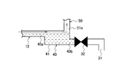
- FIG. 3 is a view showing the vicinity of the purified water holding unit of the water purification apparatus according to the first embodiment.
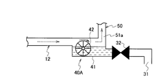
- FIG. 4 is a figure which shows the purified water holding
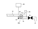
- FIG. 5 is a figure which shows the purified water holding
- FIG. 1 is a schematic diagram for explaining the water purifier concerning a 1st embodiment.
- FIG. 2 is a block diagram of the water purifier according to the first embodiment.
- FIG. 3 is a view showing the vicinity of the purified water holding unit of the water purification apparatus according to the first embodiment.
- FIG. 4 is a figure which shows the purified water holding
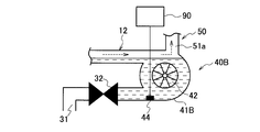
- FIG. 6 is a figure which shows the water-purifying holding
- FIG. 7 is a figure which shows the purified water holding
- FIG. 8 is a schematic view for explaining the water purifier according to the second embodiment.
- the water purifier 1 is a device for purifying raw water such as tap water.
- the water purifier 1 includes a purification unit 10 that generates purified water by purifying raw water.
- the purification unit 10 includes a separation membrane (cartridge) such as RO (reverse osmosis), NF, UF (ultrafiltration), and MF (microfiltration).
- cleaning part 10 does not necessarily need to be comprised with a separation membrane.
- the purification unit 10 may be configured by an adsorbent such as activated carbon, sand filtration, an ion exchange resin, or the like.
- a primary flow path 11 through which raw water passes is arranged upstream of the purification unit 10.
- a secondary-side flow path 12 through which the purified water generated by the purification unit 10 passes is disposed downstream of the purification unit 10.
- the raw water supply unit 20 for supplying raw water is arranged in the primary side flow path 11.
- the raw water supply unit 20 is provided with a raw water inlet 21 into which raw water flows and a first electromagnetic valve 22 that seals the raw water inlet 21.
- the secondary flow path 12 includes a faucet part 30, a purified water holding part 40, a circulation flow path 50, an ozone generation part 60 (fluid generation part), an ozone circulation part 70 (fluid circulation part), and drainage. Part 80 is provided.
- the faucet portion 30 includes a discharge port 31 that discharges purified water, a switching valve 32 that seals the discharge port 31 (see FIGS. 2 and 3), and an operation unit 33 that can operate the switching valve 32 (so-called faucet). ) Is provided.
- a purified water holding unit 40 is disposed on the upstream side of the faucet unit 30.
- the purified water holding unit 40 is disposed between the purification unit 10 and the faucet unit 30 and is configured to hold purified water. In addition, the detail of the purified water holding
- the circulation channel 50 branches from the purified water holding unit 40 or a channel located on the downstream side of the purified water holding unit 40 and communicates from the branched point to the upstream side.
- the circulation channel 50 branches from the purified water holding unit 40 and communicates with the outlet side of the purification unit 10.
- a second electromagnetic valve 51 that seals the one end 51 a is provided at one end 51 a (the end on the purified water holding unit 40 side) of the circulation channel 50.
- a third electromagnetic valve 52 that seals the other end 52a is provided at the other end 52a of the circulation channel 50 (an end portion on the purification unit 10 side).
- An ozone generation unit 60 and an ozone circulation unit 70 are disposed in the middle of the circulation channel 50.
- the ozone generator 60 generates ozone gas (fluid) containing a sterilizing component inside the secondary channel 12 and the circulation channel 50.
- the ozone generator 60 generates ozone gas by an electrolysis method such as a diamond electrode or an ozone ultraviolet method.
- the ozone circulation unit 70 is disposed between the third electromagnetic valve 52 and the ozone generation unit 60 and circulates ozone gas inside the secondary side flow path 12 and the circulation flow path 50. Specifically, the ozone circulation unit 70 allows the ozone gas generated by the ozone generation unit 60 to pass over the purified water holding unit 40 and then flows into the circulation channel 50. That is, the ozone circulation unit 70 circulates ozone gas from the one end 51a of the circulation channel 50 toward the other end 52a.
- the ozone circulation unit 70 is configured by a pump, for example.
- the drainage part 80 discharges the purified water inside the secondary side flow path 12.
- the drainage unit 80 is configured by branching from the secondary side flow path 12.
- the drainage portion 80 is provided with a drainage port 81 for draining purified water and a fourth electromagnetic valve 82 for sealing the drainage port 81.
- the water purifier 1 further includes a control unit 90 that controls each unit and performs various calculations.
- the control unit 90 is configured by a computer having a CPU, a memory unit, a time measuring unit, and the like. As shown in FIG. 2, the control unit 90 includes a first electromagnetic valve 22, a switching valve 32, a second electromagnetic valve 51, a third electromagnetic valve 52, a fourth electromagnetic valve 82, an ozone generation unit 60, an ozone circulation. Unit 70 is connected.
- the control unit 90 includes a normal mode in which the purified water generated by the purification unit 10 is discharged from the faucet unit 30 (discharge port 31), and a sterilization mode in which ozone gas is circulated inside the secondary side flow path 12 and the circulation flow path 50. And switch.
- the purified water holding unit 40 includes a box-shaped tank 41 that stores purified water.
- One end 51 a of the circulation channel 50 communicates with the upper surface downstream side of the purified water holding unit 40.
- the inflow part 40a into which purified water flows in, and the outflow part 40b from which purified water flows out are formed.
- the inflow portion 40a is provided at a position higher than the outflow portion 40b.
- the discharge port 31 mentioned above is connected to the outflow part 40b.
- the purified water holding part 40 is provided at a position lower than the secondary side flow path 12.
- the purified water holding unit 40 is preferably provided at a position lower than the first electromagnetic valve 22, the third electromagnetic valve 52, and the fourth electromagnetic valve 82.
- (1-3-2) Sterilization Mode In the sterilization mode, the first electromagnetic valve 22 and the switching valve 32 are closed, and the second electromagnetic valve 51 and the third electromagnetic valve 52 are opened. At this time, when the inside of the secondary side flow path 12 is blocked by purified water, the fourth electromagnetic valve 82 is opened, and after the purified water is discharged from the drain port 81, the fourth electromagnetic valve 82 is closed. Thereby, the inside of the secondary side flow path 12 and the circulation flow path 50 will be in a humidified state.
- the purified water containing ozone gas is discharged from the discharge port 31 to the outside by opening the switching valve 32 when the sterilization mode is switched to the normal mode. Thereby, the faucet part 30 (discharge port 31) is sterilized.
- the water purification apparatus 1 includes the purification unit 10, the purified water holding unit 40, the circulation channel 50, the ozone generation unit 60, and the ozone circulation. Part 70.
- generation part 60 can circulate through the secondary side flow path 12 and the circulation flow path 50.
- the secondary side flow path 12 can be sterilized reliably and the inside of the water purifier 1 can be kept hygienic.
- the ozone gas generated by the ozone generation unit 60 always passes through the purified water holding unit 40 when circulating through the secondary channel 12 and the circulation channel 50. For this reason, ozone gas is humidified by the purified water held inside the purified water holding unit 40, and the bactericidal action by the ozone gas can be effectively exhibited. For this reason, in order to exhibit the bactericidal action by ozone gas effectively, it is not necessary to provide a humidifier like the conventional water purifier, Therefore The energy consumption of the water purifier 1 can be suppressed.
- the purified water holding unit 40 is configured by a tank 41. Thereby, the purified water passing through the secondary side flow path 12 can be reliably stored in the tank 41. For this reason, ozone gas can be humidified easily, without providing a humidifier like the past.
- the inflow portion 40a communicating with the secondary side flow path 12 is provided at a position higher than the outflow portion 40b. That is, the purified water holding unit 40 is provided at a position lower than the secondary side flow path 12. Thereby, purified water does not block the inside of the secondary side flow path 12. For this reason, it becomes easy for ozone gas to pass through the inside of the secondary side flow path 12, and the secondary side flow path 12 can be sterilized more reliably. Moreover, even if the purified water inside the secondary side flow path 12 is drained from the drainage part 80, a fixed amount of purified water can be stored in the purified water holding part 40, and ozone gas can be humidified easily.
- the discharge port 31 is connected to the outflow portion 40b.
- the purified water holding unit 40A further includes the following configuration in addition to the configuration of the purified water holding unit 40 of the water purification apparatus 1 according to the first embodiment. That is, as shown in FIG. 4, the purified water holding unit 40A includes a box-shaped tank 41 that stores purified water, and a rotating mechanism 42 (area increasing mechanism) that increases the surface area of the purified water held inside the tank 41. .
- the rotation mechanism 42 includes a plurality of wings that can rotate with respect to the axis.
- the rotation mechanism 42 is rotated by purified water flowing through the secondary side flow path 12 and the purified water holding unit 40 ⁇ / b> A, and ozone gas circulating inside the secondary side flow path 12 and the circulation flow path 50.
- the rotation mechanism 42 may rotate the wing portion by driving a motor (not shown) connected to the shaft center.
- the purified water holding unit 40A includes the tank 41 and the rotation mechanism 42, so that the purified water inside the tank 41 can be rippled. For this reason, the surface area of the purified water inside the tank 41 is increased, and the ozone gas is further easily humidified.
- the purified water holding unit 40 ⁇ / b> A is provided with a purified water sensor 43 (purified water state detection device) that detects the state of purified water (e.g., water level, amount of water, water quality) held in the tank 41. It may be done.
- the state of purified water indicates general properties such as chemical components and physical and electrical properties of purified water, and the purified water sensor 43 detects the state of purified water by at least one of these properties. Any configuration may be used. Thereby, the water purification amount (water discharge amount) etc. inside the tank 41 can be grasped, and the timing for sterilizing the water purification device 1 can be measured.
- the tank 41 is formed in a box shape.
- the tank 41B is formed in a cylindrical shape, as shown in FIG. Specifically, an inflow portion 41a into which purified water flows and an outflow portion 41b from which purified water flows out are formed in the tank 41B.
- the inflow portion 41a is provided at a position higher than the outflow portion 41b.
- the rotation mechanism 42 has a plurality of wings as in the case of the water purification apparatus according to the first modification of the first embodiment, and is rotated by water purification or ozone gas.
- the rotation mechanism 42 may rotate the wing portion by driving a motor (not shown) connected to the shaft center.
- maintenance part 40A of the purified water apparatus 1 which concerns on the modification 1 of 1st Embodiment are obtained. be able to. Furthermore, by forming the tank 41B in a cylindrical shape, purified water is easily stored in the tank 41B, and ozone gas is further easily humidified.
- the purified water holding unit 40B is provided with a purified water sensor 44 (purified water state detection device) that detects the state of purified water (for example, water level, amount of water, water quality) held in the tank 41B. It may be done. Thereby, the amount of water purification (water discharge amount) etc. inside the tank 41B can be grasped, and the timing for sterilizing the water purification apparatus 1 can be measured.
- a purified water sensor 44 purified water state detection device
- the tank 41B is not necessarily formed in a cylindrical shape, and may be any size or shape that allows the rotation mechanism 42 to rotate. Moreover, the rotation mechanism 42 does not necessarily need to be a rotation mechanism, and should just be what can make the purified water inside the tank 41B, such as an ultrasonic wave, ripple (bubbling).
- the circulation flow path 50 branches from the purified water holding unit 40 and communicates with the outlet side of the purification unit 10.
- the water purifier 2 which concerns on 2nd Embodiment, it branches to the entrance side and exit side of the purification
- the circulation channel 50 includes a primary-side annular channel 510 that communicates with the primary-side channel 11 and a secondary-side annular channel 520 that communicates with the secondary-side channel 12. Branch.
- the primary side annular flow path 510 is provided with a fifth electromagnetic valve 511 that seals the primary side annular flow path 510.
- the secondary side annular flow path 520 is provided with a third electromagnetic valve 521 that seals the secondary side annular flow path 520.
- a three-way valve 530 (flow path switching mechanism) that can branch a fluid to either the primary side annular path 510 or the secondary side annular path 520 at a branch point between the primary side annular path 510 and the secondary side annular path 520.
- the three-way valve 530 is provided at the branch point between the primary side annular channel 510 and the secondary side annular channel 520.
- ozone gas can be passed through the primary side flow path 11 and the secondary side flow path 12.
- the primary side flow path 11 and the secondary side flow path 12 can be sterilized reliably, and the inside of the water purifier 2 can be kept more hygienic.
- ozone gas passes through the purification unit 10 via the primary-side annular flow path 510 and the primary-side flow path 11.
- cleaning part 10 can be decomposed
- the purification unit 10 is configured by an adsorbent such as activated carbon
- ozone gas is rendered harmless by passing through the purification unit 10.
- the secondary side flow path 12 is sterilized, and the primary side flow path 11 is sterilized after that. For this reason, the inside of the water purifier 1 can be kept more hygienic.
- the water purifier according to the embodiment of the present invention can be modified as follows. Specifically, although the water purifier 1 was demonstrated as the thing provided with the drainage part 80, it is not limited to this, The drainage part 80 does not need to be provided.
- maintenance part 40 was demonstrated as what is comprised with the tank 41, it is not limited to this, It is comprised with cotton, cloth, sponge, a porous material, a synthetic resin fiber (for example, polymer) etc. May be.
- the water purifier which can keep an inside hygienic can be provided, suppressing energy consumption.
Landscapes
- Life Sciences & Earth Sciences (AREA)
- Hydrology & Water Resources (AREA)
- Engineering & Computer Science (AREA)
- Environmental & Geological Engineering (AREA)
- Water Supply & Treatment (AREA)
- Chemical & Material Sciences (AREA)
- Organic Chemistry (AREA)
- Treatment Of Water By Oxidation Or Reduction (AREA)
- Separation Using Semi-Permeable Membranes (AREA)
- Water Treatment By Sorption (AREA)
Abstract
L'invention porte sur un appareil de purification d'eau (1), lequel appareil comporte : une unité de purification (10) pour produire de l'eau purifiée par purification d'eau brute ; une unité de production d'ozone (60) pour produire un gaz ozone qui contient un composant bactéricide ; une unité de circulation d'ozone (70) pour faire circuler le gaz ozone ; une unité contenant de l'eau purifiée (40) qui est disposée dans un canal de côté secondaire (12), qui est en aval de l'unité de purification (10), dans le but de contenir l'eau purifiée ; et un canal de circulation (50), qui est ramifié à partir de l'unité contenant de l'eau purifiée (40) ou à partir d'un canal positionné en aval de l'unité contenant de l'eau purifiée (40), et qui établit une communication entre le point de ramification et un point en amont. L'unité de circulation d'ozone (70) a le gaz ozone produit par l'unité de production d'ozone (60) qui traverse l'unité contenant de l'eau purifiée (40), puis qui s'écoule dans le canal de circulation (50).
Priority Applications (1)
| Application Number | Priority Date | Filing Date | Title |
|---|---|---|---|
| CN2012800151439A CN103459329A (zh) | 2011-04-08 | 2012-03-09 | 净水装置 |
Applications Claiming Priority (2)
| Application Number | Priority Date | Filing Date | Title |
|---|---|---|---|
| JP2011-086234 | 2011-04-08 | ||
| JP2011086234A JP2012217925A (ja) | 2011-04-08 | 2011-04-08 | 浄水装置 |
Publications (1)
| Publication Number | Publication Date |
|---|---|
| WO2012137576A1 true WO2012137576A1 (fr) | 2012-10-11 |
Family
ID=46968980
Family Applications (1)
| Application Number | Title | Priority Date | Filing Date |
|---|---|---|---|
| PCT/JP2012/056165 Ceased WO2012137576A1 (fr) | 2011-04-08 | 2012-03-09 | Appareil de purification d'eau |
Country Status (3)
| Country | Link |
|---|---|
| JP (1) | JP2012217925A (fr) |
| CN (1) | CN103459329A (fr) |
| WO (1) | WO2012137576A1 (fr) |
Citations (4)
| Publication number | Priority date | Publication date | Assignee | Title |
|---|---|---|---|---|
| JPH1066980A (ja) * | 1996-08-28 | 1998-03-10 | Kurita Water Ind Ltd | 超純水製造設備の殺菌装置 |
| JP2001239137A (ja) * | 2000-02-29 | 2001-09-04 | Japan Organo Co Ltd | 水処理方法および水処理装置 |
| JP2003285072A (ja) * | 2002-03-28 | 2003-10-07 | Kubota Corp | 汚水の消毒方法及びその装置 |
| JP2004041838A (ja) * | 2002-07-09 | 2004-02-12 | Kajima Corp | 水の殺菌・清浄・処理方法及び装置 |
Family Cites Families (2)
| Publication number | Priority date | Publication date | Assignee | Title |
|---|---|---|---|---|
| JPH0615282A (ja) * | 1992-06-30 | 1994-01-25 | J C Ii Eng:Kk | 浄水装置 |
| CN201517056U (zh) * | 2009-09-11 | 2010-06-30 | 董旭 | 饮水机用臭氧净化水桶 |
-
2011
- 2011-04-08 JP JP2011086234A patent/JP2012217925A/ja not_active Ceased
-
2012
- 2012-03-09 CN CN2012800151439A patent/CN103459329A/zh active Pending
- 2012-03-09 WO PCT/JP2012/056165 patent/WO2012137576A1/fr not_active Ceased
Patent Citations (4)
| Publication number | Priority date | Publication date | Assignee | Title |
|---|---|---|---|---|
| JPH1066980A (ja) * | 1996-08-28 | 1998-03-10 | Kurita Water Ind Ltd | 超純水製造設備の殺菌装置 |
| JP2001239137A (ja) * | 2000-02-29 | 2001-09-04 | Japan Organo Co Ltd | 水処理方法および水処理装置 |
| JP2003285072A (ja) * | 2002-03-28 | 2003-10-07 | Kubota Corp | 汚水の消毒方法及びその装置 |
| JP2004041838A (ja) * | 2002-07-09 | 2004-02-12 | Kajima Corp | 水の殺菌・清浄・処理方法及び装置 |
Also Published As
| Publication number | Publication date |
|---|---|
| CN103459329A (zh) | 2013-12-18 |
| JP2012217925A (ja) | 2012-11-12 |
Similar Documents
| Publication | Publication Date | Title |
|---|---|---|
| ES2613657T3 (es) | Aparato multi-etapa de desalinización de agua de mar y método de control del funcionamiento de un aparato multi-etapa de desalinización de agua de mar | |
| US10159939B2 (en) | Reverse osmosis system | |
| JP5982626B2 (ja) | 水質浄化システム | |
| CN100531870C (zh) | 膜组件及水处理系统 | |
| CN102908687B (zh) | 单站ro装置与血液透析装置的组合系统 | |
| CN102794108A (zh) | 反渗透系统 | |
| KR101492879B1 (ko) | 수처리장치 및 수처리방법 | |
| KR101439948B1 (ko) | 수처리장치 및 수처리방법 | |
| JP3777376B2 (ja) | 浄水装置及びその制御方法 | |
| KR20170130815A (ko) | Edi를 이용한 초순수 제조 시스템 | |
| KR101168914B1 (ko) | 선박 평형수 처리장치 | |
| KR101446127B1 (ko) | 수처리장치 | |
| JP6672248B2 (ja) | 飲料水生成装置 | |
| JP2013150954A (ja) | 海水淡水化装置 | |
| WO2012137576A1 (fr) | Appareil de purification d'eau | |
| CN103159344A (zh) | 净水装置 | |
| TW201219318A (en) | Water purification device and disinfection/sterilization method for water purification device | |
| KR20140021203A (ko) | 자외선램프 일체형 섬유여과기 및 이를 이용한 정수처리장치 | |
| KR101459001B1 (ko) | 수처리장치 및 수처리방법 | |
| JP5645268B2 (ja) | 浄水装置 | |
| JP2012217926A (ja) | 水処理装置 | |
| KR101476323B1 (ko) | 수처리장치 및 수처리방법 | |
| KR101447963B1 (ko) | 수처리방법 | |
| JP2006272030A (ja) | 水供給装置 | |
| KR101496307B1 (ko) | 수처리장치 및 수처리장치의 살균방법 |
Legal Events
| Date | Code | Title | Description |
|---|---|---|---|
| 121 | Ep: the epo has been informed by wipo that ep was designated in this application |
Ref document number: 12767855 Country of ref document: EP Kind code of ref document: A1 |
|
| NENP | Non-entry into the national phase |
Ref country code: DE |
|
| 122 | Ep: pct application non-entry in european phase |
Ref document number: 12767855 Country of ref document: EP Kind code of ref document: A1 |