WO2012137587A1 - Dispositif onduleur - Google Patents
Dispositif onduleur Download PDFInfo
- Publication number
- WO2012137587A1 WO2012137587A1 PCT/JP2012/056915 JP2012056915W WO2012137587A1 WO 2012137587 A1 WO2012137587 A1 WO 2012137587A1 JP 2012056915 W JP2012056915 W JP 2012056915W WO 2012137587 A1 WO2012137587 A1 WO 2012137587A1
- Authority
- WO
- WIPO (PCT)
- Prior art keywords
- voltage
- temperature
- motor
- electrolytic capacitor
- current
- Prior art date
- Legal status (The legal status is an assumption and is not a legal conclusion. Google has not performed a legal analysis and makes no representation as to the accuracy of the status listed.)
- Ceased
Links
Images


Classifications
-
- H—ELECTRICITY
- H02—GENERATION; CONVERSION OR DISTRIBUTION OF ELECTRIC POWER
- H02P—CONTROL OR REGULATION OF ELECTRIC MOTORS, ELECTRIC GENERATORS OR DYNAMO-ELECTRIC CONVERTERS; CONTROLLING TRANSFORMERS, REACTORS OR CHOKE COILS
- H02P27/00—Arrangements or methods for the control of AC motors characterised by the kind of supply voltage
- H02P27/04—Arrangements or methods for the control of AC motors characterised by the kind of supply voltage using variable-frequency supply voltage, e.g. inverter or converter supply voltage
- H02P27/06—Arrangements or methods for the control of AC motors characterised by the kind of supply voltage using variable-frequency supply voltage, e.g. inverter or converter supply voltage using DC to AC converters or inverters
-
- H—ELECTRICITY
- H02—GENERATION; CONVERSION OR DISTRIBUTION OF ELECTRIC POWER
- H02M—APPARATUS FOR CONVERSION BETWEEN AC AND AC, BETWEEN AC AND DC, OR BETWEEN DC AND DC, AND FOR USE WITH MAINS OR SIMILAR POWER SUPPLY SYSTEMS; CONVERSION OF DC OR AC INPUT POWER INTO SURGE OUTPUT POWER; CONTROL OR REGULATION THEREOF
- H02M7/00—Conversion of AC power input into DC power output; Conversion of DC power input into AC power output
- H02M7/42—Conversion of DC power input into AC power output without possibility of reversal
- H02M7/44—Conversion of DC power input into AC power output without possibility of reversal by static converters
- H02M7/48—Conversion of DC power input into AC power output without possibility of reversal by static converters using discharge tubes with control electrode or semiconductor devices with control electrode
-
- H—ELECTRICITY
- H02—GENERATION; CONVERSION OR DISTRIBUTION OF ELECTRIC POWER
- H02P—CONTROL OR REGULATION OF ELECTRIC MOTORS, ELECTRIC GENERATORS OR DYNAMO-ELECTRIC CONVERTERS; CONTROLLING TRANSFORMERS, REACTORS OR CHOKE COILS
- H02P1/00—Arrangements for starting electric motors or dynamo-electric converters
- H02P1/02—Details of starting control
- H02P1/022—Security devices, e.g. correct phase sequencing
-
- H—ELECTRICITY
- H02—GENERATION; CONVERSION OR DISTRIBUTION OF ELECTRIC POWER
- H02P—CONTROL OR REGULATION OF ELECTRIC MOTORS, ELECTRIC GENERATORS OR DYNAMO-ELECTRIC CONVERTERS; CONTROLLING TRANSFORMERS, REACTORS OR CHOKE COILS
- H02P1/00—Arrangements for starting electric motors or dynamo-electric converters
- H02P1/16—Arrangements for starting electric motors or dynamo-electric converters for starting dynamo-electric motors or dynamo-electric converters
-
- H—ELECTRICITY
- H02—GENERATION; CONVERSION OR DISTRIBUTION OF ELECTRIC POWER
- H02P—CONTROL OR REGULATION OF ELECTRIC MOTORS, ELECTRIC GENERATORS OR DYNAMO-ELECTRIC CONVERTERS; CONTROLLING TRANSFORMERS, REACTORS OR CHOKE COILS
- H02P27/00—Arrangements or methods for the control of AC motors characterised by the kind of supply voltage
- H02P27/04—Arrangements or methods for the control of AC motors characterised by the kind of supply voltage using variable-frequency supply voltage, e.g. inverter or converter supply voltage
- H02P27/06—Arrangements or methods for the control of AC motors characterised by the kind of supply voltage using variable-frequency supply voltage, e.g. inverter or converter supply voltage using DC to AC converters or inverters
- H02P27/08—Arrangements or methods for the control of AC motors characterised by the kind of supply voltage using variable-frequency supply voltage, e.g. inverter or converter supply voltage using DC to AC converters or inverters with pulse width modulation
-
- H—ELECTRICITY
- H02—GENERATION; CONVERSION OR DISTRIBUTION OF ELECTRIC POWER
- H02P—CONTROL OR REGULATION OF ELECTRIC MOTORS, ELECTRIC GENERATORS OR DYNAMO-ELECTRIC CONVERTERS; CONTROLLING TRANSFORMERS, REACTORS OR CHOKE COILS
- H02P29/00—Arrangements for regulating or controlling electric motors, appropriate for both AC and DC motors
- H02P29/60—Controlling or determining the temperature of the motor or of the drive
- H02P29/68—Controlling or determining the temperature of the motor or of the drive based on the temperature of a drive component or a semiconductor component
-
- H—ELECTRICITY
- H02—GENERATION; CONVERSION OR DISTRIBUTION OF ELECTRIC POWER
- H02M—APPARATUS FOR CONVERSION BETWEEN AC AND AC, BETWEEN AC AND DC, OR BETWEEN DC AND DC, AND FOR USE WITH MAINS OR SIMILAR POWER SUPPLY SYSTEMS; CONVERSION OF DC OR AC INPUT POWER INTO SURGE OUTPUT POWER; CONTROL OR REGULATION THEREOF
- H02M1/00—Details of apparatus for conversion
- H02M1/32—Means for protecting converters other than automatic disconnection
- H02M1/327—Means for protecting converters other than automatic disconnection against abnormal temperatures
-
- H—ELECTRICITY
- H02—GENERATION; CONVERSION OR DISTRIBUTION OF ELECTRIC POWER
- H02M—APPARATUS FOR CONVERSION BETWEEN AC AND AC, BETWEEN AC AND DC, OR BETWEEN DC AND DC, AND FOR USE WITH MAINS OR SIMILAR POWER SUPPLY SYSTEMS; CONVERSION OF DC OR AC INPUT POWER INTO SURGE OUTPUT POWER; CONTROL OR REGULATION THEREOF
- H02M1/00—Details of apparatus for conversion
- H02M1/36—Means for starting or stopping converters
-
- H—ELECTRICITY
- H02—GENERATION; CONVERSION OR DISTRIBUTION OF ELECTRIC POWER
- H02P—CONTROL OR REGULATION OF ELECTRIC MOTORS, ELECTRIC GENERATORS OR DYNAMO-ELECTRIC CONVERTERS; CONTROLLING TRANSFORMERS, REACTORS OR CHOKE COILS
- H02P29/00—Arrangements for regulating or controlling electric motors, appropriate for both AC and DC motors
- H02P29/60—Controlling or determining the temperature of the motor or of the drive
- H02P29/62—Controlling or determining the temperature of the motor or of the drive for raising the temperature of the motor
Definitions
- the present invention relates to an inverter device that drives an electric motor by generating an AC voltage from a DC voltage smoothed by an electrolytic capacitor, and particularly relates to an inverter device that is intended to be able to use an electrolytic capacitor even in a low temperature environment. .
- This type of conventional inverter device selectively drives the three switching elements on the upper phase side and the three switching elements on the lower phase side of the inverter circuit, so that three phases of U, V, and W from the DC voltage are obtained.
- a motor that drives a motor by generating voltage is provided with a smoothing capacitor that smoothes a DC voltage of a power source of an inverter circuit (see, for example, Patent Document 1).
- a smoothing capacitor that smoothes a DC voltage of a power source of an inverter circuit.
- an electrolytic capacitor, a film capacitor, or the like is used as the smoothing capacitor.
- the in-vehicle inverter device may be used in a low temperature environment, and when an electrolytic capacitor is used in such an environment, the equivalent series resistance of the electrolytic capacitor increases. As a result, the ripple voltage increases, and the voltage applied to the switching element and the electrolytic capacitor exceeds the withstand voltage or becomes a reverse voltage, so that an electric compressor, for example, as an electric motor cannot be operated.
- an object of the present invention is to provide an inverter device that can cope with such problems and can use an electrolytic capacitor even in a low temperature environment.
- an inverter device comprises an electrolytic capacitor that smoothes a rectified voltage into a DC voltage, an inverter circuit that generates an AC voltage from the DC voltage and drives an electric motor, and the inverter circuit includes: Control means for controlling driving of the plurality of switching elements, and temperature detection means for detecting the temperature of the electrolytic capacitor and outputting the detected temperature to the control means, wherein the control means is obtained by the temperature detection means.
- Control means for controlling driving of the plurality of switching elements
- temperature detection means for detecting the temperature of the electrolytic capacitor and outputting the detected temperature to the control means, wherein the control means is obtained by the temperature detection means.
- the temperature of the electrolytic capacitor that smoothes the rectified voltage into a DC voltage is acquired by the temperature detection means, and when the acquired temperature is lower than a predetermined target temperature, before the normal operation of the motor is started.
- the control means controls the driving of the plurality of switching elements included in the inverter circuit, and a current limited so that the ripple voltage of the DC voltage is within an allowable value is supplied to the motor, and the temperature of the electrolytic capacitor is set to the target temperature. Let the temperature rise.
- control means selects a specific switching element from among the plurality of switching elements of the inverter circuit and activates the electric motor before starting the electric motor, and allows the motor to be energized, and the DC voltage
- the current supplied to the motor is controlled on the basis of a set current value that can suppress the ripple voltage within the allowable value.
- control means changes in correlation with a constant set current value that can limit the ripple voltage of the DC voltage within an allowable value or a temperature of the electrolytic capacitor until a predetermined time has elapsed since the start of the electric motor.
- the electric current supplied to the electric motor may be controlled based on the set current value.
- control means may change in correlation with a constant set rotational speed capable of limiting the ripple voltage of the DC voltage within an allowable range or a temperature of the electrolytic capacitor until a predetermined time has elapsed since the start of the electric motor.
- the current supplied to the electric motor may be controlled based on the set rotational speed.
- control means correlates with a constant pulse width modulation carrier frequency that can limit the ripple voltage of the DC voltage within an allowable range until a certain time has elapsed from the start of the motor, or the temperature of the electrolytic capacitor.
- the current supplied to the electric motor may be controlled based on the pulse width modulation carrier frequency that changes.
- the warm-up mode is performed in which the motor is energized to raise the temperature of the electrolytic capacitor to a temperature at which the normal operation of the motor can be started. Therefore, a voltage exceeding the withstand voltage is applied to the switching element and the electrolytic capacitor due to the large ripple voltage, and it is possible to prevent the occurrence of an accident that destroys these elements. Therefore, an inexpensive and small electrolytic capacitor can be used even in a low temperature environment, and the inverter device can be miniaturized and the manufacturing cost can be reduced.
- the warm-up mode is implemented by energizing the motor with a current that is limited so that the ripple voltage of the DC voltage that is the power supply voltage of the inverter circuit is within the allowable value, switching is also performed during the warm-up mode. It is possible to prevent destruction of the element and the electrolytic capacitor.
- the warm-up mode can be implemented by driving on a specific switching element of the inverter circuit before the motor is started.
- the energization current to the motor is controlled based on the set current value that can suppress the ripple voltage of the DC voltage within the allowable value, so that it is ensured that a voltage exceeding the withstand voltage is applied to the switching element and the electrolytic capacitor. Can be prevented.
- the warm-up mode can be performed during a certain period of time after the start of the electric motor. Therefore, the transition to the normal operation of the electric motor can be performed smoothly.
- the current flowing to the motor is controlled based on a constant set current value that can limit the ripple voltage of the DC voltage within an allowable value, or a set current value that changes in correlation with the temperature of the electrolytic capacitor. In this case as well, it is possible to reliably prevent a voltage exceeding the breakdown voltage from being applied to the switching element and the electrolytic capacitor.
- the warm-up mode can be performed during a certain period of time after the motor is started. Therefore, the transition to the normal operation of the electric motor can be performed smoothly.
- the energization current to the motor is controlled based on a fixed set speed that can limit the ripple voltage of the DC voltage within an allowable range, or a set speed that changes in correlation with the temperature of the electrolytic capacitor. In this case as well, it is possible to reliably prevent a voltage exceeding the breakdown voltage from being applied to the switching element and the electrolytic capacitor.
- the said warming-up mode can be implemented before a fixed time passes from the time of starting of an electric motor. Therefore, the transition to the normal operation of the electric motor can be performed smoothly.
- the current flowing to the motor is controlled based on a constant pulse width modulation carrier frequency that can limit the ripple voltage of the DC voltage within an allowable range or a pulse width modulation carrier frequency that varies in correlation with the temperature of the electrolytic capacitor. Therefore, in this case as well, it is possible to reliably prevent a voltage exceeding the breakdown voltage from being applied to the switching element and the electrolytic capacitor.
- 1 is a circuit diagram showing a schematic configuration of a first embodiment of an inverter device according to the present invention; It is a block diagram which shows the control circuit of the warming-up mode in the control means of the said 1st Embodiment. It is a flowchart shown about operation
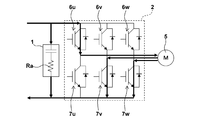
- FIG. 1 is a circuit diagram showing a schematic configuration of a first embodiment of an inverter device according to the present invention.
- This inverter device generates an AC voltage from a DC voltage smoothed by an electrolytic capacitor to drive an electric motor, and includes an electrolytic capacitor 1, an inverter circuit 2, a control means 3, and a temperature detection means 4. It is prepared for.
- the electrolytic capacitor 1 is a large-capacity aluminum electrolytic capacitor that smoothes the rectified voltage into a DC voltage.
- Such an aluminum electrolytic capacitor is small and inexpensive, but generally has a large equivalent series resistance Ra due to the resistance of the electrolytic solution, the resistance of the electrolytic paper, and the like, and becomes larger in a low temperature environment. Have.
- An inverter circuit 2 is provided so that a DC voltage smoothed by the electrolytic capacitor 1 is supplied as a power supply voltage.
- This inverter circuit 2 generates a three-phase voltage Vu, Vv, Vw from a DC voltage and supplies it to a three-phase brushless motor (hereinafter simply referred to as “motor”) 5 as an electric motor.
- the three switching elements (IGBT) 6u, 6v, 6w and three switching elements (IGBT) 7u, 7v, 7w on the lower phase side are configured.
- Control means 3 is provided in connection with the inverter circuit 2.
- the control means 3 controls the on / off drive of the six switching elements 6u to 6w and 7u to 7w of the inverter circuit 2 to appropriately operate the motor 5, and the temperature of the electrolytic capacitor 1 is determined in advance.
- the duty of the pulse width modulation (hereinafter referred to as "PWM") signal for driving the switching elements 6u to 6w and 7u to 7w of the inverter circuit 2 on and off
- PWM pulse width modulation
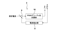
- FIG. 2 is a block diagram showing a control circuit in the warm-up mode in the control means 3.
- the warm-up mode control circuit is connected to the emitters of the lower-phase side switching elements 7u to 7w of the inverter circuit 2 or on the ground line of the inverter circuit 2 (not shown).
- the current detection unit 8 detects the energization current of the motor 5 based on the current flowing through a shunt resistor (not shown) provided in the circuit, and the current value detected by the current detection unit 8 and the ripple voltage of the DC voltage are within an allowable value.
- a comparator 9 that compares a constant set current value that can be suppressed (hereinafter referred to as “warm-up mode current value”) and a PWM signal so that the difference between the energization current value and the warm-up mode current value can be corrected.
- a PWM duty ratio calculation unit 10 for calculating the duty ratio.
- the control means 3 configured as described above executes the warm-up mode before starting the motor 5 when the temperature of the electrolytic capacitor 1 is lower than the target temperature. That is, of the three switching elements 6u to 6w on the upper phase side of the inverter circuit 2, for example, the switching element 6u is selected and turned on, the remaining switching elements 6v and 6w are selected and turned off, and the lower phase side Among the three switching elements 7u to 7w, the switching elements 7v and 7w are selected and turned on, and the remaining switching elements 7u are selected and driven off.
- the current detection unit 8 detects the energization current of the motor 5, compares the detected current value with the warm-up mode current value by the comparator 9, and the PWM duty ratio calculation unit so that the difference can be corrected.
- the 10 calculates the duty ratio of the PWM signal.
- the switching elements 6u, 7v, and 7w are turned on by the PWM signal having the calculated duty ratio to energize the motor 5.
- a current limited to the ripple voltage of the DC voltage within the allowable value flows through the inverter circuit 2 through the motor 5.
- the electrolytic capacitor 1 is heated by Joule heat generated in its equivalent series resistance Ra.
- temperature detection means 4 In the vicinity of the electrolytic capacitor 1, temperature detection means 4 is provided. This temperature detection means 4 detects the ambient temperature of the electrolytic capacitor 1 and outputs it to the control means 3, and is, for example, various temperature sensors such as a thermocouple or a resistance sensor. When the electrolytic capacitor 1 is mounted on the same substrate as the inverter circuit 2 or is accommodated in the same space, the temperature detecting means 4 is the switching element of the inverter circuit 2 that generates the largest amount of heat. The temperature of the electrolytic capacitor 1 may be estimated by detecting the temperature in the vicinity. However, in the following description, the temperature detecting means 4 detects the ambient temperature of the electrolytic capacitor 1 and electrolyzes it. A case where the temperature of the capacitor 1 is estimated will be described.
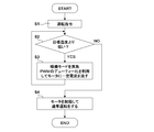
- step S1 when the operation switch is turned on (operation command), the power supply voltage is supplied to the inverter device and the control means 3 of the inverter device is activated.
- step S 2 the temperature detection means 4 detects the temperature around the electrolytic capacitor 1, and the detection output is sent to the control means 3.
- the determination unit (not shown) of the control means 3 estimates the detected temperature acquired by the temperature detection means 4 as the temperature of the electrolytic capacitor 1, and performs the operation in the warm-up mode that is preset and stored in a memory (not shown). It compares with the target temperature for determining whether to implement or not. If the detected temperature is lower than the target temperature, step S2 is “YES” and the process proceeds to step S3.
- step S3 the PWM duty ratio calculation unit 10 of the control means 3 calculates the duty ratio of the PWM signal based on the warm-up mode current value set in advance and stored in the memory, and the calculated duty ratio is calculated.
- the switching element 6u on the upper phase side of the inverter circuit 2 is turned on by the PWM signal, while the switching elements 7v and 7w on the lower phase side are turned on.
- the inverter circuit 2 and the motor 5 are supplied with a current limited so that the ripple voltage of the DC voltage is within the allowable value, and the operation in the warm-up mode is performed.
- the switching element to be turned on of the inverter circuit 2 is fixed to, for example, the switching element 6u on the upper phase side and the switching elements 7v and 7w on the lower phase side, for example, the motor 5 remains stopped. .
- the electrolytic capacitor 1 is warmed by Joule heat generated in its equivalent series resistance Ra and raised in temperature.
- the energizing current of the motor 5 is a current flowing through a shunt resistor provided connected to the emitters of the lower-phase switching elements 7u to 7w of the inverter circuit 2 or a shunt resistor provided on the ground line of the inverter circuit 2.
- the PWM duty ratio calculator 10 compares the detected current with the warm-up mode current value by the comparator 9 and corrects the difference. Therefore, during the warm-up mode, a current that is limited so that the ripple voltage of the DC voltage is within the allowable value flows through the motor 5 at all times. In this case, the warm-up mode current value may change in correlation with the temperature of the electrolytic capacitor 1.
- step S2 and step S3 are repeatedly executed until the detected temperature reaches the target temperature in step S2, that is, until “NO” is determined in step S2.
- step S4 the process proceeds to step S4, where the plurality of switching elements 6u to 6w and 7u to 7w of the inverter circuit 2 are sequentially turned on / off according to a predetermined procedure.
- the motor 5 is started by being turned off. As a result, the motor 5 performs normal operation.
- FIG. 5 is a flowchart showing another operation in the warm-up mode of the first embodiment.
- step S10 when the operation switch is turned on (operation command), the power supply voltage is supplied to the inverter device, and the control means 3 of the inverter device is activated.
- step S ⁇ b> 11 the temperature around the electrolytic capacitor 1 is detected by the temperature detection means 4, and the detection output is sent to the control means 3.
- the detected temperature acquired by the temperature detection means 4 is estimated as the temperature of the electrolytic capacitor 1, and it is determined whether or not to perform the warm-up mode operation stored in advance in the memory. Compare with target temperature for judgment.
- the determination in step S11 is “YES”, and the process proceeds to step S12.
- step S12 the PWM duty ratio calculation unit 10 of the control means 3 calculates the duty ratio of the PWM signal based on the warm-up mode current value set in advance and stored in the memory, and the calculated duty ratio is calculated. For example, the switching element 6u on the upper phase side of the inverter circuit 2 is turned on by the PWM signal, while the switching elements 7v and 7w on the lower phase side are turned on. As a result, as shown by a thick solid line in FIG. 4, the inverter circuit 2 and the motor 5 are supplied with a current limited so that the ripple voltage of the DC voltage is within the allowable value, and the operation in the warm-up mode is performed.
- the switching element to be turned on of the inverter circuit 2 is fixed to, for example, the switching element 6u on the upper phase side and the switching elements 7v and 7w on the lower phase side, for example, the motor 5 remains stopped. . In this way, while the limited current is applied to the motor 5, the electrolytic capacitor 1 is warmed by Joule heat generated in its equivalent series resistance Ra and raised in temperature.
- step S13 the elapsed time is measured by a timer, and when a predetermined time set in advance and stored in the memory has elapsed, the process proceeds to step S14.
- the temperature and equivalent series resistance Ra of the electrolytic capacitor 1 and the energization time have a relationship shown in FIG. 6, for example. That is, as the energization time elapses, the temperature of the electrolytic capacitor 1 increases and the equivalent series resistance Ra decreases. In both cases, it is known that when the time t elapses, the value becomes constant. Therefore, in the control example shown in FIG.
- the temperature of the electrolytic capacitor 1 and the elapsed time t at which the equivalent series resistance Ra is constant after the current of the current value for the warm-up mode is supplied to the motor 5 are previously experimentally determined. Then, the elapsed time t is stored in the memory.
- step S13 when the temperature of the electrolytic capacitor 1 rises to the target temperature after a certain period of time, the process proceeds to step S14, and the six switching elements 6u to 6w and 7u to 7w of the inverter circuit 2 are sequentially turned on / off according to a predetermined procedure. Driven, the motor 5 is started. As a result, the motor 5 performs normal operation.
- step S11 If the detected temperature has already reached the target temperature in step S11, the determination in step S11 is “NO” and the process proceeds to step S14.
- the six switching elements 6u ⁇ 6w and 7u to 7w are sequentially turned on / off according to a predetermined procedure, the motor 5 is started, and the motor 5 performs normal operation.
- the current detector 8 is provided on the shunt resistor provided by connecting to the emitters of the lower-phase switching elements 7u to 7w of the inverter circuit 2 or on the ground line of the inverter circuit 2.
- the current flowing through the shunt resistor (not shown) connected to the negative electrode side of the electrolytic capacitor 1 is detected, and the ripple voltage of the DC voltage is allowed based on the current.
- the motor 5 may be energized with a current limited to be within.
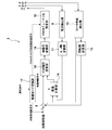
- FIG. 7 is a circuit diagram showing a schematic configuration of the second embodiment of the inverter device of the present invention, and is a block diagram showing a circuit configuration of the control means 3.
- the control means 3 in the second embodiment controls the inverter circuit 2 so as to carry out the warm-up mode until a certain time has elapsed since the start of the motor 5, and includes a current detector 8 and d, q Axis converter 11, rotor angle detector 12, rotation speed calculator 13, current calculator 14, comparator 9, applied voltage calculator 15, phase voltage converter 16, and PWM duty ratio calculator 10 and a warm-up mode switching unit 17.
- the current detection unit 8 is connected to the emitters of the lower phase side switching elements 7u to 7w of the inverter circuit 2 and based on the current flowing through a shunt resistor (not shown) of the motor 5, the three phase currents Iu, Iv, Iw of the motor 5. Are respectively detected.
- the d and q axis converter 11 converts the three-phase currents Iu, Iv and Iw into d and q axis currents Id and Iq.
- the rotor angle detector 12 detects the rotor angle, and calculates the rotor angle using, for example, a hall sensor or based on the phase voltage and phase current.
- the rotational speed calculation unit 13 calculates based on the detected rotor angle and calculates the rotational speed of the rotor.
- the current calculation unit 14 calculates a current value based on the currents Id and Iq and the rotor angle, and calculates the phase lag or phase advance of the current.
- the comparator 9 compares the calculated rotor rotation speed with the target rotation speed and outputs the difference.
- the applied voltage calculator 15 calculates the voltage for driving the motor 5 and adjusts the phase of the voltage.
- the phase voltage converter 16 converts the d and q-axis voltages Vd and Vq to the three-phase voltages Vu, Vv and Vw.
- the PWM duty ratio calculation unit 10 calculates the duty ratio of the PWM signal based on the three-phase voltages Vu, Vv, and Vw, and the switching elements 6u to 6w of the inverter circuit 2 based on the PWM signal having the calculated duty ratio. , 7u to 7w are driven on.
- the warm-up mode switching unit 17 compares the temperature input from the temperature detection means 4 with the target temperature of the warm-up mode and needs to execute the warm-up mode. In some cases, one of the current limit command for the warm-up mode, the rotation speed limit command, and the PWM carrier frequency limit command that can limit the ripple voltage of the DC voltage of the inverter circuit 2 within an allowable value is selected and output.
- the current limit command is output to the current calculation unit 14. Further, when the warm-up mode is performed based on the rotation speed limit command, the rotation speed limit command is output to the memory. Further, when executing the warm-up mode based on the PWM carrier frequency limit command, the PWM carrier frequency limit command is output to the PWM duty ratio calculation unit 10.
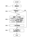
- step S20 when the operation switch is turned on and an operation command is issued, the process proceeds to step S21, and it is determined whether or not to implement the warm-up mode.
- step S21 the ambient temperature of the electrolytic capacitor 1 input from the temperature detection means 4 (hereinafter simply referred to as “temperature of the electrolytic capacitor 1”) is set in advance by a determination unit provided in the control means 3. Compare with the target temperature stored in memory. When the temperature of the electrolytic capacitor 1 is lower than the target temperature, the determination in step S21 is “YES”, the warm-up mode switching unit 17 is turned on to select the current-limiting warm-up mode, and the warm-up mode switching unit The current limit command is output from 17 to the current calculation unit 14, and the process proceeds to step S22.
- the current value calculated by the current calculation unit 14 is limited to a preset current value based on the current limit command.
- the limited current value is a preset current value that is preset and stored in the memory, for example, can limit the ripple voltage of the DC voltage within an allowable value, and is lower than that during normal operation.
- Current value may be a current value set so as to change in correlation with the temperature of the electrolytic capacitor 1, and may be a current value that changes based on a table created in advance by experiment and stored in a memory.
- the current calculation is performed based on the currents Id and Iq converted from the three-phase currents Iu, Iv, and Iw by the d and q axis conversion unit 11 to the d and q axes and the rotor angle detected by the rotor angle detection unit 12.
- the current value calculated by the unit 14 is limited to the set current value. In addition, you may change the said electric current value, monitoring the temperature of the electrolytic capacitor 1, and the ripple voltage of DC voltage irrespective of the said table.
- the applied voltage calculation unit 15 calculates an applied voltage for driving the motor 5 based on the set current value and the rated target rotational speed. Further, the phase voltage converter 16 converts the voltage into three-phase voltages Vu, Vv, Vw, and the PWM duty ratio calculator 10 calculates the duty ratio of the PWM signal based on the three-phase voltages Vu, Vv, Vw. The switching elements 6u to 6w and 7u to 7w of the inverter circuit 2 are turned on based on the PWM signal having the calculated duty ratio. As a result, a current that is limited so that the ripple voltage of the DC voltage is within the allowable value is supplied to the motor 5, and the motor 5 is started. Thereafter, the motor 5 rotates while maintaining the rated number of rotations under the limited current value.
- step S23 the elapsed time from the start of the motor 5 is counted by a timer. Then, when a predetermined time has elapsed, the process proceeds to step S24.
- step S24 the warm-up mode switching unit 17 is driven off based on the output signal of the timer indicating that a certain time has elapsed, and the current limitation based on the set current value is released. Thereby, the warm-up mode ends.
- step S25 the control means 3 detects the three-phase current detected by the current detector 8 based on the current flowing through the shunt resistor provided connected to the emitters of the lower-phase switching elements 7u to 7w of the inverter circuit 2.
- the current value calculated by the current calculation unit 14 based on the currents Id and Iq converted from du and q axes from Iu, Iv, and Iw and the rotor angle detected by the rotor angle detection unit 12, and detected by the rotor angle detection unit 12
- the applied voltage Vd to the motor 5 is applied to the motor 5 by the applied voltage calculator 15 based on the difference between the rotational speeds calculated by comparing the rotational speed calculated based on the rotor angle and the rated target rotational speed by the comparator.
- Vq is calculated. Further, the phase voltage converter 16 converts the applied voltages Vd and Vq on the d and q axes to the three-phase voltages Vu, Vv and Vw, and the PWM duty ratio calculator 10 based on the three-phase voltages Vu, Vv and Vw. After calculating the duty ratio of the PWM signal, the switching elements 6u to 6w and 7u to 7w of the inverter circuit 2 are appropriately turned on by the PWM signal having the calculated duty ratio, so that the motor 5 is normally operated.
- step S21 if the temperature of the electrolytic capacitor 1 has already reached the target temperature, step S21 is “NO”, the process proceeds to step S25, and the motor 5 performs normal operation.
- step S30 when the operation switch is turned on and an operation command is issued, the process proceeds to step S31, and it is determined whether or not to implement the warm-up mode.
- step S31 the temperature of the electrolytic capacitor 1 input from the temperature detection means 4 is set in advance by a determination unit provided in the control means 3 and compared with the target temperature stored in the memory.
- the determination in step S31 is “YES”, and the warm-up mode switching unit 17 is turned on to select the warm-up mode with the rotational speed limit, so that the warm-up mode is switched.
- a rotation speed limit command is output from the unit 17 to the memory and set in advance and stored in the memory. For example, a constant set rotation speed that can limit the ripple voltage of the DC voltage within an allowable value (lower than that during normal operation) Read the number of revolutions) from the memory. Then, the process proceeds to step S32.
- the set rotational speed is a rotational speed that is set so as to change in correlation with the temperature of the electrolytic capacitor 1, and is a rotational speed that changes based on a table created in advance by experiment and stored in the memory. May be. In this case, the rotation speed may be changed while monitoring the temperature of the electrolytic capacitor 1 and the ripple voltage of the DC voltage, without depending on the table.
- step S32 the motor 5 is started on the basis of the predetermined rotational speed read from the memory based on the rotational speed restriction command, and a current that can restrict the ripple voltage of the DC voltage within the allowable value is energized. In this state, the engine is operated with the rotation speed limited to the set rotation speed.
- the control means 3 generates the three-phase currents Iu, Iv, Iw in the current detector 8 based on the current flowing through the shunt resistor provided connected to the emitters of the lower-phase switching elements 7u-7w of the inverter circuit 2. Then, the d and q axis conversion unit 11 converts the three-phase currents Iu, Iv, and Iw into the d and q axes to obtain the currents Id and Iq. The rotor detected by the currents Id and Iq and the rotor angle detection unit 12 is detected. Based on the angle, the current calculation unit 14 calculates the current value and the phase lag or phase advance.
- the rotational speed calculator 13 calculates the actual rotor rotational speed. Then, the rotation speed is compared with the set rotation speed by the comparison section, and the difference is output. In the applied voltage calculation section 15, the difference between the current value calculated by the current calculation section 14 and the rotation speed output from the comparison section. Based on the amount, applied voltages Vd and Vq for driving the motor 5 are calculated. Further, the applied voltages Vd and Vq are converted into the three-phase voltages Vu, Vv and Vw by the three-phase voltage converter 16, and the PWM duty ratio calculator 10 calculates the PWM signal based on the three-phase voltages Vu, Vv and Vw.
- the switching elements 6u to 6w and 7u to 7w of the inverter circuit 2 are turned on by the PWM signal having the duty ratio. Thereby, the motor 5 rotates while maintaining the set rotational speed. At this time, the energization current to the motor 5 is maintained at a current value that can limit the ripple voltage of the DC voltage within an allowable value.
- step S33 the elapsed time from the start of the motor 5 is counted by a timer. Then, when a predetermined time has elapsed, the process proceeds to step S34.
- step S34 the warm-up mode switching unit 17 is turned off based on the output signal of the timer indicating that a predetermined time has elapsed, and the rotational speed limit based on the set rotational speed is released. Thereby, the warm-up mode ends.
- step S35 the target rotational speed of the rated value is read from the memory, the rotational speed is controlled so as to be the target rotational speed, and the motor 5 is operated. Thus, the motor 5 shifts to normal operation.
- step S31 if the temperature of the electrolytic capacitor 1 has already reached the target temperature, step S31 is “NO”, the process proceeds to step S35, and the motor 5 performs normal operation.
- step S40 when the operation switch is turned on and an operation command is issued, the process proceeds to step S41, and it is determined whether or not to implement the warm-up mode.
- step S41 the temperature of the electrolytic capacitor 1 input from the temperature detecting means 4 is set in advance by a determination unit provided in the control means 3 and compared with the target temperature stored in the memory.
- step S41 is determined as “YES”
- the warm-up mode switching unit 17 is turned on, and the warm-up mode with PWM carrier frequency restriction is selected, and step S42 is performed. Proceed to
- step S42 the warm-up mode switching unit 17 outputs a PWM carrier frequency limit command to the PWM duty ratio calculation unit 10, and can limit the ripple voltage of the DC voltage within an allowable value, for example, a constant PWM carrier frequency (normal operation) Carrier frequency is set to a carrier frequency lower than that).
- the PWM duty ratio calculation unit 10 generates a PWM signal based on the set carrier frequency, calculates the duty ratio of the generated PWM signal based on the rated target rotational speed, and the calculated
- the switching elements 6u to 6w and 7u to 7w of the inverter circuit 2 are turned on by the PWM signal having the duty ratio to start the motor 5.
- the set carrier frequency is a carrier frequency that changes in correlation with the temperature of the electrolytic capacitor 1, and may be a carrier frequency that changes based on a table that is created in advance by experiment and stored in the memory. .
- the motor 5 is operated with the carrier frequency limited (reduced) to the set carrier frequency in a state in which a current that can limit the ripple voltage of the DC voltage within an allowable value is applied.
- the carrier frequency may be changed while monitoring the temperature of the electrolytic capacitor 1 and the ripple voltage of the DC voltage, regardless of the above table.
- control means 3 calculates the duty ratio of the PWM signal generated by the set carrier frequency based on the detected three-phase currents Iu, Iv, Iw, the rotor angle, and the target rotational speed, and the calculated The switching elements 6u to 6w and 7u to 7w of the inverter circuit 2 are turned on by the duty ratio PWM signal.
- the motor 5 operates while maintaining the target rotational speed.
- the energization current to the motor 5 is maintained at a current value that can limit the ripple voltage of the DC voltage within an allowable value.
- step S43 the elapsed time from the start of the motor 5 is counted by a timer. Then, when a predetermined time has passed, the process proceeds to step S44.
- step S44 the warm-up mode switching unit 17 is turned off based on the output signal of the timer indicating that a certain time has elapsed, and the carrier frequency limitation (reduction) by the set carrier frequency is released. Thereby, the warm-up mode ends.
- step S45 the motor 5 is operated under the control of the carrier frequency during normal operation, and the motor 5 shifts to normal operation.
- step S41 if the temperature of the electrolytic capacitor 1 has already reached the target temperature, step S41 is “NO”, the process proceeds to step S45, and the motor 5 performs normal operation.
- the warm-up mode is performed with the current, the rotational speed, or the carrier frequency limited to each independently.
- the present invention is not limited thereto, and the current, the rotational speed, You may carry out combining the restriction
- at least two of current limitation, rotation speed limitation, and carrier frequency limitation may be selected and the warm-up mode may be performed for a certain period of time.
- the warm-up mode switching unit 17 may not be provided.
- the shunt resistor provided in connection with the emitters of the lower-phase switching elements 7u to 7w of the inverter circuit 2 or the shunt provided on the ground line of the inverter circuit 2 is used.
- the present invention is not limited to this, and the lower phase side
- the ripple current is estimated from the current (detection current) flowing through the shunt resistor connected to the emitters of the switching elements 7u to 7w or the shunt resistor provided on the ground line of the inverter circuit 2, and the ripple current is an allowable value.
- the energization current to the motor 5 may be limited so as to be within.
- the ripple current can be estimated by the sum of the AC components of the detection current.
- the relationship between the detection current and the ripple current is measured in advance by experiments, and the ripple current can be estimated from this relationship.
- the three-phase inverter circuit 2 has been described.
- the present invention is not limited to this, and the inverter circuit 2 may have any number of phases, for example, four phases. It is good to set appropriately according to.
Landscapes
- Engineering & Computer Science (AREA)
- Power Engineering (AREA)
- Computer Security & Cryptography (AREA)
- Inverter Devices (AREA)
- Control Of Ac Motors In General (AREA)
- Control Of Motors That Do Not Use Commutators (AREA)
Abstract
La présente invention comporte : un condensateur électrolytique (1) qui lisse une tension redressée pour produire une tension en courant continu ; un circuit onduleur (2) qui génère une tension en courant alternatif à partir de la tension en courant continu et entraîne un moteur (5) ; un moyen de commande (3) qui commande l'entraînement de multiples éléments de commutation (6u-6w, 7u-7w) possédés par le circuit onduleur (2) ; et un moyen de détection de température (4) qui détecte la température du condensateur électrolytique (1) et délivre le résultat au moyen de commande (3). Lorsque la température obtenue par le moyen de détection de température (4) est inférieure à une température cible prédéterminée, avant de commencer le fonctionnement normal du moteur (5), le moyen de commande (3) augmente la température du condensateur électrolytique (1) jusqu'à la valeur cible par excitation du moteur (5) avec un courant qui est restreint de sorte que la tension d'ondulation de la tension en courant continu est à l'intérieur d'une valeur autorisée. Ainsi, le condensateur électrolytique peut être utilisé même dans un environnement à basse température.
Priority Applications (3)
| Application Number | Priority Date | Filing Date | Title |
|---|---|---|---|
| EP12768245.8A EP2690778B1 (fr) | 2011-04-07 | 2012-03-16 | Dispositif onduleur |
| US14/110,354 US20140028238A1 (en) | 2011-04-07 | 2012-03-16 | Inverter Device |
| CN201280023395.6A CN103534931A (zh) | 2011-04-07 | 2012-03-16 | 逆变器装置 |
Applications Claiming Priority (2)
| Application Number | Priority Date | Filing Date | Title |
|---|---|---|---|
| JP2011-085176 | 2011-04-07 | ||
| JP2011085176A JP5925425B2 (ja) | 2011-04-07 | 2011-04-07 | インバータ装置 |
Publications (1)
| Publication Number | Publication Date |
|---|---|
| WO2012137587A1 true WO2012137587A1 (fr) | 2012-10-11 |
Family
ID=46968990
Family Applications (1)
| Application Number | Title | Priority Date | Filing Date |
|---|---|---|---|
| PCT/JP2012/056915 Ceased WO2012137587A1 (fr) | 2011-04-07 | 2012-03-16 | Dispositif onduleur |
Country Status (5)
| Country | Link |
|---|---|
| US (1) | US20140028238A1 (fr) |
| EP (1) | EP2690778B1 (fr) |
| JP (1) | JP5925425B2 (fr) |
| CN (1) | CN103534931A (fr) |
| WO (1) | WO2012137587A1 (fr) |
Cited By (2)
| Publication number | Priority date | Publication date | Assignee | Title |
|---|---|---|---|---|
| DE102012224206A1 (de) * | 2012-12-21 | 2014-06-26 | Tridonic Gmbh & Co. Kg | LED-Konverter mit Froststart-Funktion |
| EP2924876A4 (fr) * | 2012-11-26 | 2016-07-27 | Toyota Jidoshokki Kk | Dispositif onduleur |
Families Citing this family (18)
| Publication number | Priority date | Publication date | Assignee | Title |
|---|---|---|---|---|
| DE102012106033A1 (de) * | 2012-07-05 | 2014-01-09 | Halla Visteon Climate Control Corporation 95 | Verfahren zum Betreiben eines Inverters eines elektrischen Kältemittelverdichters unter Verwendung von elektrolytischen Zwischenkreis-Kondensatoren |
| JP6024601B2 (ja) * | 2012-11-26 | 2016-11-16 | 株式会社豊田自動織機 | インバータの暖機制御装置 |
| JP6155807B2 (ja) * | 2013-04-26 | 2017-07-05 | 三菱電機株式会社 | 点灯装置および照明器具 |
| JP6217554B2 (ja) * | 2014-07-30 | 2017-10-25 | 株式会社豊田自動織機 | インバータ装置 |
| DE102014219474B4 (de) * | 2014-09-25 | 2022-06-09 | Valeo Siemens Eautomotive Germany Gmbh | Verfahren zum Betrieb von Leistungshalbleitern |
| JP6633367B2 (ja) | 2015-11-30 | 2020-01-22 | サンデン・オートモーティブコンポーネント株式会社 | インバータ装置 |
| JP6402708B2 (ja) | 2015-12-24 | 2018-10-10 | 株式会社豊田自動織機 | インバータ装置 |
| CN105763035B (zh) * | 2016-04-11 | 2018-06-29 | 广州金升阳科技有限公司 | 一种提高低温启动能力的方法及电路 |
| AT15439U1 (de) * | 2016-05-20 | 2017-09-15 | Tridonic Gmbh & Co Kg | Elektrisches Vorschaltgerät mit Extremtemperaturschutz |
| JP6978661B2 (ja) * | 2017-02-27 | 2021-12-08 | ダイキン工業株式会社 | 電力変換装置 |
| CN107070190B (zh) * | 2017-04-26 | 2020-06-09 | 华为技术有限公司 | 一种电源装置及其电容加热控制方法 |
| JP7300307B2 (ja) | 2019-05-07 | 2023-06-29 | サンデン株式会社 | インバータ装置 |
| JP7439412B2 (ja) * | 2019-08-08 | 2024-02-28 | 株式会社デンソー | 電力変換装置 |
| DE102020205919A1 (de) * | 2020-05-12 | 2021-11-18 | Robert Bosch Gesellschaft mit beschränkter Haftung | Steuervorrichtung und Steuerverfahren für ein elektrisches Antriebssystem und elektrisches Antriebssystem |
| TWI749857B (zh) * | 2020-11-10 | 2021-12-11 | 致新科技股份有限公司 | 馬達控制器 |
| US20220149762A1 (en) * | 2020-11-11 | 2022-05-12 | Global Mixed-Mode Technology Inc. | Motor controller |
| EP4002664A1 (fr) * | 2020-11-11 | 2022-05-25 | Valeo Siemens eAutomotive Germany GmbH | Onduleur, procédé de configuration d'un onduleur, procédé de commande d'un onduleur et programme informatique correspondant |
| CN114204850A (zh) * | 2021-12-08 | 2022-03-18 | 浙江吉利控股集团有限公司 | 一种电动压缩机低温预热方法和设备 |
Citations (5)
| Publication number | Priority date | Publication date | Assignee | Title |
|---|---|---|---|---|
| JP2006109624A (ja) * | 2004-10-06 | 2006-04-20 | Matsushita Electric Ind Co Ltd | ブラシレスdcモータの駆動装置 |
| JP2009060776A (ja) * | 2007-08-06 | 2009-03-19 | Toyota Industries Corp | 電動機の制御方法及び制御装置 |
| JP2009138521A (ja) | 2007-12-03 | 2009-06-25 | Sanden Corp | 電動圧縮機の制御方法 |
| JP2009189181A (ja) * | 2008-02-07 | 2009-08-20 | Toyota Motor Corp | モータ駆動システムおよびその制御方法ならびに電動車両 |
| JP2011010534A (ja) * | 2009-05-27 | 2011-01-13 | Jtekt Corp | モータ制御装置および電動パワーステアリング装置 |
Family Cites Families (8)
| Publication number | Priority date | Publication date | Assignee | Title |
|---|---|---|---|---|
| JPH08107683A (ja) * | 1994-10-03 | 1996-04-23 | Mitsubishi Electric Corp | 電動機の運転制御装置及び絶縁型双方向直流電圧変換回路 |
| JP3616152B2 (ja) * | 1995-02-09 | 2005-02-02 | 松下電器産業株式会社 | 自動車用電動コンプレッサー駆動装置 |
| CN1211908C (zh) * | 2001-02-14 | 2005-07-20 | 丰田自动车株式会社 | 动力输出装置及装有该装置的车辆、动力输出装置的控制方法和存储媒体及程序、驱动装置及装有该装置的车辆、驱动装置的控制方法和存储媒体及程序 |
| US6737828B2 (en) * | 2001-07-19 | 2004-05-18 | Matsushita Electric Industrial Co., Ltd. | Washing machine motor drive device |
| KR100654487B1 (ko) * | 2003-09-09 | 2006-12-05 | 마츠시타 덴끼 산교 가부시키가이샤 | 컨버터 회로, 모터 구동 장치, 압축기, 공기 조화기,냉장고, 전기 세탁기, 송풍기, 전기 청소기 및 히트펌프급탕기 |
| ES2299986T3 (es) * | 2005-03-09 | 2008-06-01 | Patent-Treuhand-Gesellschaft Fur Elektrische Gluhlampen Mbh | Disposicion de proteccion frente a sobrecarga para convertidores electronicos, por ejemplo para lamparas halogenas. |
| JP4462243B2 (ja) * | 2006-07-10 | 2010-05-12 | トヨタ自動車株式会社 | 負荷駆動装置およびそれを備える車両 |
| US7859207B2 (en) * | 2007-08-06 | 2010-12-28 | Kabushiki Kaisha Toyota Jidoshokki | Method and apparatus for controlling electric motor |
-
2011
- 2011-04-07 JP JP2011085176A patent/JP5925425B2/ja active Active
-
2012
- 2012-03-16 US US14/110,354 patent/US20140028238A1/en not_active Abandoned
- 2012-03-16 EP EP12768245.8A patent/EP2690778B1/fr active Active
- 2012-03-16 WO PCT/JP2012/056915 patent/WO2012137587A1/fr not_active Ceased
- 2012-03-16 CN CN201280023395.6A patent/CN103534931A/zh active Pending
Patent Citations (5)
| Publication number | Priority date | Publication date | Assignee | Title |
|---|---|---|---|---|
| JP2006109624A (ja) * | 2004-10-06 | 2006-04-20 | Matsushita Electric Ind Co Ltd | ブラシレスdcモータの駆動装置 |
| JP2009060776A (ja) * | 2007-08-06 | 2009-03-19 | Toyota Industries Corp | 電動機の制御方法及び制御装置 |
| JP2009138521A (ja) | 2007-12-03 | 2009-06-25 | Sanden Corp | 電動圧縮機の制御方法 |
| JP2009189181A (ja) * | 2008-02-07 | 2009-08-20 | Toyota Motor Corp | モータ駆動システムおよびその制御方法ならびに電動車両 |
| JP2011010534A (ja) * | 2009-05-27 | 2011-01-13 | Jtekt Corp | モータ制御装置および電動パワーステアリング装置 |
Non-Patent Citations (1)
| Title |
|---|
| See also references of EP2690778A4 |
Cited By (6)
| Publication number | Priority date | Publication date | Assignee | Title |
|---|---|---|---|---|
| EP2924876A4 (fr) * | 2012-11-26 | 2016-07-27 | Toyota Jidoshokki Kk | Dispositif onduleur |
| DE102012224206A1 (de) * | 2012-12-21 | 2014-06-26 | Tridonic Gmbh & Co. Kg | LED-Konverter mit Froststart-Funktion |
| CN105075394A (zh) * | 2012-12-21 | 2015-11-18 | 赤多尼科两合股份有限公司 | 具有霜冻启动功能的led变换器 |
| CN105075394B (zh) * | 2012-12-21 | 2017-07-21 | 赤多尼科两合股份有限公司 | 具有霜冻启动功能的led变换器 |
| EP2936929B1 (fr) * | 2012-12-21 | 2020-03-25 | Tridonic GmbH & Co. KG | Convertisseur de del avec une fonction démarrage en cas de gel |
| DE102012224206B4 (de) | 2012-12-21 | 2024-09-12 | Tridonic Gmbh & Co Kg | LED-Konverter mit Froststart-Funktion |
Also Published As
| Publication number | Publication date |
|---|---|
| US20140028238A1 (en) | 2014-01-30 |
| EP2690778B1 (fr) | 2017-05-03 |
| EP2690778A1 (fr) | 2014-01-29 |
| CN103534931A (zh) | 2014-01-22 |
| JP5925425B2 (ja) | 2016-05-25 |
| JP2012222925A (ja) | 2012-11-12 |
| EP2690778A4 (fr) | 2015-09-02 |
Similar Documents
| Publication | Publication Date | Title |
|---|---|---|
| JP5925425B2 (ja) | インバータ装置 | |
| JP5630474B2 (ja) | インバータ | |
| JP6633367B2 (ja) | インバータ装置 | |
| JP6217554B2 (ja) | インバータ装置 | |
| US7852026B2 (en) | Motor drive apparatus and motor drive control method | |
| JP5817641B2 (ja) | インバータの暖機制御装置 | |
| JP5026553B2 (ja) | Ac/dcコンバータの変換動作モードを動的に切替える機能を有するモータ駆動装置 | |
| JP6398821B2 (ja) | 回転電機の制御装置 | |
| US20150311819A1 (en) | Inverter device | |
| JP6511514B2 (ja) | モータ駆動装置 | |
| JP2009207307A (ja) | モータ駆動装置 | |
| JP6075029B2 (ja) | インバータの暖機制御装置 | |
| CN113711485B (zh) | 逆变器装置 | |
| JP3865224B2 (ja) | 電動パワーステアリング装置 | |
| JP2016077150A (ja) | インバータ装置 | |
| JP2019009940A (ja) | インバータ | |
| JP5482050B2 (ja) | モータ制御装置およびモータの欠相診断方法 | |
| JP2008011670A (ja) | インバータ装置 | |
| JP3885621B2 (ja) | 電動パワーステアリング装置 | |
| JP6020160B2 (ja) | インバータの暖機制御装置 | |
| JP2005269723A (ja) | 電動機駆動制御装置 | |
| JP3807507B2 (ja) | センサレス同期モータの駆動装置 | |
| JP2008161021A (ja) | 電動機駆動装置およびその欠相検出方法 | |
| JP2007104779A (ja) | 電流オフセット調整方法とそれを用いた電力変換装置。 | |
| JP2010213525A (ja) | 回転電機制御システム |
Legal Events
| Date | Code | Title | Description |
|---|---|---|---|
| 121 | Ep: the epo has been informed by wipo that ep was designated in this application |
Ref document number: 12768245 Country of ref document: EP Kind code of ref document: A1 |
|
| NENP | Non-entry into the national phase |
Ref country code: DE |
|
| WWE | Wipo information: entry into national phase |
Ref document number: 14110354 Country of ref document: US |
|
| REEP | Request for entry into the european phase |
Ref document number: 2012768245 Country of ref document: EP |
|
| WWE | Wipo information: entry into national phase |
Ref document number: 2012768245 Country of ref document: EP |