WO2012137641A1 - Système d'éclairage d'entrée de tunnel - Google Patents
Système d'éclairage d'entrée de tunnel Download PDFInfo
- Publication number
- WO2012137641A1 WO2012137641A1 PCT/JP2012/058117 JP2012058117W WO2012137641A1 WO 2012137641 A1 WO2012137641 A1 WO 2012137641A1 JP 2012058117 W JP2012058117 W JP 2012058117W WO 2012137641 A1 WO2012137641 A1 WO 2012137641A1
- Authority
- WO
- WIPO (PCT)
- Prior art keywords
- tunnel
- entrance
- illumination
- tunnel entrance
- adaptation
- Prior art date
- Legal status (The legal status is an assumption and is not a legal conclusion. Google has not performed a legal analysis and makes no representation as to the accuracy of the status listed.)
- Ceased
Links
Images










Classifications
-
- E—FIXED CONSTRUCTIONS
- E21—EARTH OR ROCK DRILLING; MINING
- E21D—SHAFTS; TUNNELS; GALLERIES; LARGE UNDERGROUND CHAMBERS
- E21D9/00—Tunnels or galleries, with or without linings; Methods or apparatus for making thereof; Layout of tunnels or galleries
- E21D9/14—Layout of tunnels or galleries; Constructional features of tunnels or galleries, not otherwise provided for, e.g. portals, day-light attenuation at tunnel openings
-
- H—ELECTRICITY
- H05—ELECTRIC TECHNIQUES NOT OTHERWISE PROVIDED FOR
- H05B—ELECTRIC HEATING; ELECTRIC LIGHT SOURCES NOT OTHERWISE PROVIDED FOR; CIRCUIT ARRANGEMENTS FOR ELECTRIC LIGHT SOURCES, IN GENERAL
- H05B47/00—Circuit arrangements for operating light sources in general, i.e. where the type of light source is not relevant
- H05B47/10—Controlling the light source
- H05B47/105—Controlling the light source in response to determined parameters
- H05B47/11—Controlling the light source in response to determined parameters by determining the brightness or colour temperature of ambient light
-
- H—ELECTRICITY
- H05—ELECTRIC TECHNIQUES NOT OTHERWISE PROVIDED FOR
- H05B—ELECTRIC HEATING; ELECTRIC LIGHT SOURCES NOT OTHERWISE PROVIDED FOR; CIRCUIT ARRANGEMENTS FOR ELECTRIC LIGHT SOURCES, IN GENERAL
- H05B47/00—Circuit arrangements for operating light sources in general, i.e. where the type of light source is not relevant
- H05B47/10—Controlling the light source
- H05B47/105—Controlling the light source in response to determined parameters
- H05B47/115—Controlling the light source in response to determined parameters by determining the presence or movement of objects or living beings
- H05B47/125—Controlling the light source in response to determined parameters by determining the presence or movement of objects or living beings by using cameras
-
- F—MECHANICAL ENGINEERING; LIGHTING; HEATING; WEAPONS; BLASTING
- F21—LIGHTING
- F21W—INDEXING SCHEME ASSOCIATED WITH SUBCLASSES F21K, F21L, F21S and F21V, RELATING TO USES OR APPLICATIONS OF LIGHTING DEVICES OR SYSTEMS
- F21W2131/00—Use or application of lighting devices or systems not provided for in codes F21W2102/00-F21W2121/00
- F21W2131/10—Outdoor lighting
- F21W2131/101—Outdoor lighting of tunnels or the like, e.g. under bridges
-
- Y—GENERAL TAGGING OF NEW TECHNOLOGICAL DEVELOPMENTS; GENERAL TAGGING OF CROSS-SECTIONAL TECHNOLOGIES SPANNING OVER SEVERAL SECTIONS OF THE IPC; TECHNICAL SUBJECTS COVERED BY FORMER USPC CROSS-REFERENCE ART COLLECTIONS [XRACs] AND DIGESTS
- Y02—TECHNOLOGIES OR APPLICATIONS FOR MITIGATION OR ADAPTATION AGAINST CLIMATE CHANGE
- Y02B—CLIMATE CHANGE MITIGATION TECHNOLOGIES RELATED TO BUILDINGS, e.g. HOUSING, HOUSE APPLIANCES OR RELATED END-USER APPLICATIONS
- Y02B20/00—Energy efficient lighting technologies, e.g. halogen lamps or gas discharge lamps
- Y02B20/40—Control techniques providing energy savings, e.g. smart controller or presence detection
-
- Y—GENERAL TAGGING OF NEW TECHNOLOGICAL DEVELOPMENTS; GENERAL TAGGING OF CROSS-SECTIONAL TECHNOLOGIES SPANNING OVER SEVERAL SECTIONS OF THE IPC; TECHNICAL SUBJECTS COVERED BY FORMER USPC CROSS-REFERENCE ART COLLECTIONS [XRACs] AND DIGESTS
- Y02—TECHNOLOGIES OR APPLICATIONS FOR MITIGATION OR ADAPTATION AGAINST CLIMATE CHANGE
- Y02B—CLIMATE CHANGE MITIGATION TECHNOLOGIES RELATED TO BUILDINGS, e.g. HOUSING, HOUSE APPLIANCES OR RELATED END-USER APPLICATIONS
- Y02B20/00—Energy efficient lighting technologies, e.g. halogen lamps or gas discharge lamps
- Y02B20/72—Energy efficient lighting technologies, e.g. halogen lamps or gas discharge lamps in street lighting
Definitions
- the present invention relates to a tunnel entrance lighting technology.
- tunnel entrance illumination is provided as described in Non-Patent Document 1 and the like.
- This tunnel entrance illumination is intended to alleviate the sudden changes in brightness that occur when the driver approaches the tunnel during the day and the delay in eye adaptation that occurs immediately after entering the tunnel.
- the entrance illumination is a combination of entrance illumination and basic illumination.
- the entrance lighting is generally a method using only artificial lighting, but there is also a method using natural light (natural light lighting).
- tunnel entrance illumination is realized by guiding natural light from a solar collector to a tunnel entrance using a light guide.
- the installation scale of the tunnel entrance illumination is determined by the design speed and outdoor brightness of the tunnel.
- the outdoor luminance is, for example, an average luminance in a circular visual field with a viewing angle of 20 degrees as viewed from a point 150 m before the tunnel wellhead, and is expressed as an outdoor luminance L 20 or the like.
- An object of the present invention is to provide a tunnel entrance illumination technique capable of realizing energy saving while maintaining performance as entrance illumination in a tunnel using artificial illumination for entrance illumination.
- the present invention is provided on a road in front of a tunnel wellhead, a pre-adaptation structure that constitutes a pre-adaptation section in which the natural illumination light amount (illuminance or luminance) of the road surface by natural light gradually decreases in the traveling direction, Entrance illumination means for forming an illumination light amount distribution in the tunnel traveling direction according to the natural illumination light amount in the pre-adapted structure before the tunnel well opening,
- a tunnel entrance lighting system comprising:
- the present invention it is possible to provide a tunnel entrance lighting technique capable of realizing significant energy saving while maintaining performance as entrance lighting in a tunnel using artificial lighting for entrance lighting.
- the tunnel entrance illumination technique is to install a pre-adaptation section, that is, a structure for reducing the adaptation brightness of the driver's eyes before the conventional tunnel entrance illumination. is there.
- the tunnel entrance illumination technique according to the second aspect of the present embodiment is such that the extension of the pre-adaptation section is a viewing distance corresponding to the design speed.
- the tunnel entrance illumination technique of the third aspect of the present embodiment uses a coefficient k of 0.01 ⁇ k ⁇ 0.1, and the road surface luminance in the first half of the pre-adaptation interval is the outdoor luminance L 20.
- the road surface luminance at the end of the second half of the pre-adaptation interval is set to the outdoor luminance L 20 ⁇ 0.4k.
- the required luminance at the boundary of the entrance illumination is the outdoor luminance L 20 ⁇ 0.2k.
- the tunnel entrance illumination technology of the fifth aspect of the present embodiment illuminates the pre-adaptation section with natural light.
- the tunnel entrance illumination technology according to the sixth aspect of the present embodiment is to extract natural light with a louver in the pre-adaptation section.
- the tunnel entrance illumination technology according to the seventh aspect of the present embodiment is to extract natural light with a shade in the pre-adaptation section.
- the tunnel entrance illumination technique of the eighth aspect of the present embodiment is to install a daylighting part of an optical duct in the pre-adaptation section.
- the tunnel entrance illumination technology of the ninth embodiment is such that the light output part of the light duct is part of the pre-adaptation section and the section is installed in the tunnel.
- the tunnel entrance illumination technique uses the light output portion of the optical duct as part of the tunnel entrance illumination.
- the tunnel entrance illumination technology of the eleventh aspect of the present embodiment is to install solar cells in the pre-adaptation section.
- the light source of the entrance illumination is a variable light quantity illumination lamp, and the variable light quantity illumination lamp of the entrance illumination is turned on by the generated power of the solar cell installed in the acclimatization section. To do.
- the adaptation brightness of the driver's eyes before entering the tunnel entrance illumination section can be reduced by installing the pre-adaptation section.
- the adaptation brightness of the driver's eyes from the distance corresponding to the viewing distance from the tunnel wellhead is reduced. Can be reduced.
- the road surface brightness L PA1 of the first half of the pre-adaptation section is the field brightness L 20 ⁇ k, and the road surface at the end of the second half of the pre-adaptation section.
- the required road surface brightness L th BL0 at the boundary of the entrance illumination is set to the outdoor brightness L 20 ⁇ 0.2k, so that the driver approaching and entering the tunnel while securing the visibility, as compared to the tunnel entrance illumination not including the pre-adaptation period, it is possible to reduce the road surface brightness L th of the boundary 1/5.
- artificial illumination can be eliminated by illuminating the pre-adaptation section with natural light.
- artificial lighting can be made unnecessary by collecting natural light with a louver in the pre-adaptation section.
- artificial lighting can be made unnecessary by collecting natural light with a shade in the pre-adaptation section.
- the daylighting portion of the light duct is installed in the preconditioning section, and the collected light is used as part of the preconditioning section or as part of the tunnel entrance illumination.
- artificial lighting is unnecessary or a part of it can be omitted.
- the light output portion of the optical duct is made a part of the adaptation section, and the section is installed in the tunnel, thereby extending the installation of the adaptation section outside the tunnel. It can be shortened.
- part of the artificial illumination can be omitted by making the light output part of the optical duct part of the tunnel entrance part illumination.
- the structure of the pre-adaptation section can be used for multiple purposes, and the power generated by the solar cell can be used. .
- the light source of the entrance illumination is a variable light quantity illumination lamp, and the variable light quantity illumination lamp of the entrance illumination is turned on by the generated power of the solar cell installed in the acclimatization section. Some or all of the commercial power supply can be omitted.
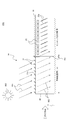
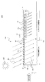
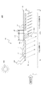
- FIG. 1 is a schematic cross-sectional view showing an example of the principle configuration of a tunnel entrance lighting system according to an embodiment of the present invention.
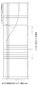
- FIG. 2 is an illumination curve diagram showing the relationship between the distance from the wellhead and the required illumination level (road surface brightness) in the pre-adaptation section.
- the road surface brightness such as the pre-adaptation section illumination curve C1 that forms the pre-adaptation section LA in front of the wellhead 10a of the tunnel 10 existing on the route of the road 11.
- a pre-adaptation structure 12 (a later-described pre-adaptation structure 12A to a pre-adaptation structure 12R) that realizes the distribution is installed.
- a plurality of basic illuminations 10c are arranged in the traveling direction, and further, an entrance illumination 10b is added to the basic illumination 10c in the vicinity of the wellhead 10a, thereby causing a black hole phenomenon that occurs before entering the tunnel.
- an illumination having a road surface luminance distribution such as a tunnel entrance illumination curve C2 to be described later corresponding to a later-adapted section illumination curve C1 is realized. Yes.
- the extension of the pre-adaptation section LA shall be a viewing distance corresponding to the design speed. For example, when the design speed is 100 km / h and 80 km / h, they are 160 m and 110 m, respectively.
- the relationship between the distance from the tunnel entrance 10 a of the tunnel 10 and the required illumination level (road surface brightness) in the adaptation zone LA is, for example, the adaptation zone illumination curve. It is set like C1.
- a pre-adaptation section is installed 160 m in front from the wellhead 10a, and the illumination level (road surface brightness L PA2 ) of the first half of the pre-adaptation section on the road 11 is a value obtained by multiplying the outdoor brightness L 20 by a coefficient k.
- FIG. 2 shows an example in which the coefficient k is 10%.
- the field intensity L 20 is the average luminance of the circular field of view viewing angle 20 degrees as viewed from ⁇ side view corresponding to the design speed. This includes the case where the measurement distance of the outdoor brightness is 150 m (fixed) before the wellhead regardless of the design speed.
- the second half of the end of the pre-adaptation period LA i.e., wellhead 10a
- illumination level road surface brightness L PA2
- the illumination level (road surface luminance L th ) of the wellhead 10a is 4%.
- the illumination level (road surface brightness) of the pre-adaptation section LA is an example based on the recommended value of the International Commission on Illumination (CIE), and is not limited to these values.
- FIG. 3 shows an entrance lighting curve C0 in the conventional case where no acclimatization section is installed, and is an example of a curve recommended by the International Lighting Commission.
- FIG. 4 is a diagram showing a comparison between a conventional entrance illumination curve and an entrance illumination curve according to the present embodiment.
- the pre-adaptation section LA pre-adaptation structure 12 for realizing the pre-adaptation section illumination curve C1 illustrated in FIG. 2
- the operation existing in the pre-adaptation section LA since the person's eyes are adapted to the outdoor luminance L 20 ⁇ k, the curve C2 only needs to consider the dark adaptation of the retina.
- the adaptation luminance of the driver's eyes approaching the tunnel and the outdoor luminance.
- the illumination at the tunnel entrance is controlled by the outdoor luminance as an alternative to the adaptation luminance of the driver's eyes.
- the reference International Lighting Commission (CIE)
- the driver's eye adaptation luminance is equivalent to the foveal adaptation luminance and equivalent light. It is represented by a luminance difference discrimination threshold corresponding to the curtain luminance.
- the former is the adaptation luminance at the portion of the visual line center where the viewing angle is about 2 degrees, and the latter is the luminance representing the degree of intraocular scattering.
- an adaptive luminance is obtained with respect to the sum of the luminance difference discrimination thresholds.
- the luminance in the central visual field is also about 1/10 in the pre-adaptation section, but the fovea does not immediately adapt to this luminance. This is because there is a time delay of adaptation of the retina, a so-called dark adaptation phenomenon, which needs to be considered.
- the fovea adaptation brightness is dominant over the equivalent light curtain brightness, and the adaptation brightness is about 20% before entering the pre-adaptation section.
- the road surface luminance L th of the curve C2 is the outdoor luminance L 20 ⁇ 0.2k. According to the present embodiment, the road surface brightness L th can be reduced to 1/5.
- the tunnel entrance illumination curve C2 in this embodiment can be shifted to the lower luminance side as a whole than the conventional entrance illumination curve C0, and the power consumption of the entrance illumination 10b is greatly increased. Can be reduced.
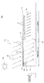
- FIG. 5 is a schematic cross-sectional side view showing the configuration of the tunnel entrance illumination system that is Embodiment 1 of the present invention.
- the tunnel entrance illumination system 20A includes a plurality of adaptation lights 12b provided on the ceiling or side wall in the vicinity of the tunnel 10a and the adaptation structure 12A that constitutes the adaptation section LA.
- the illumination lamp 22 is comprised.
- the plurality of illumination lamps 22 are arranged along the traveling direction of a vehicle that travels on the road 11 and enters the tunnel 10 from the well 10a, emits artificial illumination light 22a, and the road surface of the road 11 at the entrance in the tunnel 10 Illuminate.
- the illumination lamp 22 includes, for example, a light-emitting diode (LED) illumination lamp or an organic electroluminescence (EL) illumination lamp, and a variable light quantity illumination lamp capable of adjusting the illuminance of the artificial illumination light 22a by an applied voltage. It has become.
- LED light-emitting diode
- EL organic electroluminescence
- the pre-adaptation structure 12A provided in the pre-adaptation section LA includes a housing 21b provided along the road 11 and a ceiling portion covering at least the upper portion of the road 11 of the housing 21b.
- a plurality of solar battery panels 21 installed along the traveling direction of the road 11 are provided.
- the frame 21b may be, for example, a rectangular gate shape including the well 10a of the tunnel 10 or an arch shape including the well 10a, and does not limit the shape of the frame.
- region of the solar cell panel 21 is good also as a structure arrange
- the plurality of solar battery panels 21 of the pre-adapted structure 12A are installed with a dimming gap 21a, and natural light 901 emitted from the sun 900 passes through the road surface of the road 11 with a desired transmittance by the dimming gap 21a. Dimmed to indirect light 902 to illuminate.
- the individual suns are set so that the luminance distribution on the road surface of the road 11 by the indirect light 902 in the pre-adaptation section LA becomes the above-mentioned pre-adaptation section illumination curve C1.
- a dimming gap 21a between the battery panels 21 (for example, a mutual inclination angle or posture) is set.
- the solar cell panel 21 is connected to the illumination lamp 22 provided inside the tunnel 10 via the wiring 23, and the power consumed by the illumination lamp 22 is covered by the power generated by the solar cell panel 21 by the natural light 901. Is called.
- the intensity of the natural light 901 that is, the output power of the solar battery panel 21
- the intensity of the artificial illumination light 22a required for the illumination lamp 22 that is, the power consumption.
- the individual illumination lamps 22 are connected in parallel to the wiring 23 via the branch wiring 23a.
- a load resistance RW is arranged in the branch wiring 23a so that the luminance distribution of the tunnel entrance illumination curve C2 described above is realized, and the open-circuit voltage of the solar panel 21 is the withstand voltage of the illumination lamp 22.
- the load resistance RW in each lighting fixture 22 is set so as not to exceed.
- the power consumption of the illumination lamp 22 is covered by the power generated by the solar cell panel 21 constituting the pre-adaptation structure 12A. Energy saving can be realized.
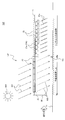
- FIG. 6 is a schematic cross-sectional side view illustrating a configuration example of a tunnel entrance illumination system that is Embodiment 2 of the present invention.
- the illuminance meter 25 is installed on an arbitrary road side portion of the acclimatization section LA, and the illumination level of the illumination lamp 22 constituting the tunnel entrance illumination is set.
- the point which provided the control apparatus 24 to control differs from the above-mentioned Example 1.
- control device 24 is connected to the plurality of illumination lamps 22 via the control wiring 24a, and the illuminometer 25 is connected to the control device 24 via the signal wiring 25a.
- control apparatus 24 is based on the illumination intensity of the road surface of the road 11 in the pre-adaptation area LA measured by the illumination meter 25, and the level of the artificial illumination light 22a of each illumination lamp 22 is the above-mentioned tunnel entrance of FIG. It controls so that it may have distribution of partial illumination curve C2.
- the solar cell panel 21 of the pre-adaptation structure 12B may supply power to the illumination lamp 22 as in the first embodiment, or may supply power to other external equipment.
- the control wiring 24a and the signal wiring 25a are omitted.
- the measurement signal and the control signal are transmitted using the power line communication (PLC) technology. Wiring may be simplified by performing communication.
- the tunnel entrance illumination curve C2 is further set based on the value of the pre-adaptation section illumination curve C1 actually measured by the illuminometer 25. It is possible to realize the comfortable passage of the tunnel 10 by controlling accurately and more accurately according to the adaptation state of the eyes of the driver of the vehicle entering the tunnel 10.
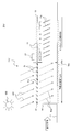
- FIG. 7 is a schematic cross-sectional side view illustrating a configuration example of a tunnel entrance illumination system that is Embodiment 3 of the present invention.
- the luminance meter 26 is installed in the adaptation zone LA in the adaptation structure 12C, and connected to the control device 24 via the signal wiring 26a.
- the light quantity distribution of the artificial illumination light 22a in the plurality of illumination lamps 22 is controlled to be the tunnel entrance illumination curve C2. To do.
- FIG. 8 is a schematic cross-sectional side view illustrating a configuration example of a tunnel entrance illumination system that is Embodiment 4 of the present invention.
- the tunnel entrance illumination system 20D of the fourth embodiment is provided with a pre-adapted structure 12D having a movable solar panel 31 instead of the solar panel 21 in the first embodiment. Different from Example 1.
- a plurality of movable solar battery panels 31 are mounted on the ceiling of the housing 30 movably via the swing shaft 31b.
- the illuminance distribution of the indirect light 902 that is, the road surface luminance distribution of the road 11
- the adaptation zone illumination curve C1 It controls to become.
- the oscillating shaft 31b has an appropriate rotation resistance that can withstand the dead weight of the movable solar panel 31, and when manually adjusted to an arbitrary angle, the set angle and posture are maintained by the sliding resistance.
- the movable solar panel 31 adjusts the angle according to the season in which the altitude of the sun 900 is different, the installation latitude, etc., and realizes or maintains the road surface luminance distribution approximated to the adaptation adaptation section illumination curve C1. be able to.
- FIG. 9 is a schematic cross-sectional side view illustrating a configuration example of a tunnel entrance illumination system that is Embodiment 5 of the present invention.
- a tilt control device 27 for controlling the attitude of the movable solar panel 31 is further provided in the configuration of the fourth embodiment. It has a configuration.
- the tilt control device 27 stores information on the daily movement trajectory of the sun 900 according to the season, the latitude of the installation location of the tunnel 10, and the like.
- FIG. 10 is a schematic cross-sectional side view illustrating a configuration example of a tunnel entrance illumination system that is Embodiment 6 of the present invention.
- a pre-adaptation structure using a transmission type solar cell panel 32 instead of the solar cell panel 21 is different from the first embodiment.
- this pre-adaptation structure 12F a plurality of transmission type solar cell panels 32 are laid on the ceiling portion of the casing 30, and natural light 901 passes through the transmission type solar cell panel 32, so that the road 11 in the pre-adaptation section LA can be seen.
- the indirect light 902 to be illuminated is used.
- a road surface luminance distribution of the indirect light 902 approximated to the above-mentioned adaptation adaptation section illumination curve C1 can be realized by combining and laying a plurality of transmission type solar cell panels 32 having different transmittances.
- the transmittance-type solar cell panel 32 having a high transmittance and the transmittance are increased so that the ratio of the transmittance-type solar cell panel 32 having a low transmittance is increased from the entrance side of the pre-adaptation section LA toward the tunnel entrance 10a.
- By combining and laying a low transmission solar cell panel 32 it is possible to realize a road surface luminance distribution of the indirect light 902 that approximates the pre-adaptation section illumination curve C1.
- FIG. 11 is a schematic cross-sectional side view illustrating a configuration example of a tunnel entrance illumination system that is Embodiment 7 of the present invention.
- the louver 41 provided with the light control gap 41a is provided in the ceiling part of the housing 40 installed in the pre-adaptation section LA.
- the luminance distribution is made to be a distribution that approximates the pre-adaptation section illumination curve C1 of FIG.
- FIG. 12 is a schematic cross-sectional side view illustrating a configuration example of a tunnel entrance illumination system that is Embodiment 8 of the present invention.
- a pre-adaptation structure 12H having a movable louver 51 is installed in the pre-adaptation section LA, and the angle of the louver can be adjusted for each season.
- a plurality of movable louvers 51 are installed on the ceiling portion of the housing 50 via each of the plurality of louver swing shafts 52.
- the dimming gap 51a through which the natural light 901 passes and forms the indirect light 902 is adjusted, and the road surface of the road 11 by the indirect light 902 in the pre-adaptation section LA.
- the effect described in FIG. 4 is obtained by setting and controlling the road surface luminance distribution so as to have a distribution that approximates the pre-adaptation section illumination curve C1 of FIG.
- FIG. 13 is a schematic sectional side view which shows the structural example of the tunnel entrance part illumination system which is Example 9 of this invention.
- the pre-adaptation structure 12J in the tunnel entrance illumination system 20J of the ninth embodiment is the tilt control device 27 that automatically controls the angle of each movable louver 51 in the pre-adaptation structure 12H of the eighth embodiment. Is provided.
- FIG. 14 is a schematic cross-sectional side view illustrating a configuration example of a tunnel entrance illumination system that is Embodiment 10 of the present invention.
- the pre-adaptation structure 12K in the tunnel entrance illumination system 20K of the tenth embodiment uses the solar cell integrated louver 61 instead of the louver 41 in the pre-adaptation structure 12G of the seventh embodiment illustrated in FIG. It has a configuration.
- the plurality of solar cell integrated louvers 61 installed on the ceiling portion of the housing 60 are subjected to the road surface luminance distribution of the indirect light 902 from the natural light 901 by the individual dimming gaps 61a like the pre-adaptation section illumination curve C1 described above. And generating power by irradiating with natural light 901.
- the pre-adapting structure 12K includes the solar cell integrated louver 61, so that it can be used as a power generation facility.
- FIG. 15 is a schematic cross-sectional side view illustrating a configuration example of a tunnel entrance illumination system that is Embodiment 11 of the present invention.
- the tunnel entrance illumination system 20L of the eleventh embodiment a configuration in which the solar cell integrated movable louver 62 is disposed on the upper portion of the housing 60 via the louver swing shaft 63 as the pre-adaptation structure 12L.
- the louver oscillating shaft 63 has an appropriate rotational resistance that can withstand the weight of the solar cell integrated movable louver 62 and supports the solar cell integrated movable louver 62, and can be individually operated at an arbitrary angle by manual operation.
- This solar cell integrated movable louver 62 can be fixed.
- the solar cell integrated movable louver 62 is connected to the illumination lamp 22 via the wiring 23 and the branch wiring 23a (load resistance RW), and the illumination lamp is powered by the electric power generated by the solar cell integrated movable louver 62.
- the point which lights 22 is the same as that of 20 A of tunnel entrance part illumination systems illustrated by the above-mentioned FIG.
- FIG. 16 is a schematic sectional side view showing a configuration example of a tunnel entrance illumination system that is Embodiment 12 of the present invention.
- the pre-adaptation structure 12M of the tunnel entrance illumination system 20M of the twelfth embodiment includes a tilt control device 27 that automatically controls the angle of the solar cell integrated louver 61 illustrated in the eleventh embodiment.
- a tilt control device 27 that automatically controls the angle of the solar cell integrated louver 61 illustrated in the eleventh embodiment.
- other configurations are the same as those of the eleventh embodiment.
- the tilt control device 27 stores information on the daily movement trajectory of the sun 900 according to the season, the latitude of the installation location of the tunnel 10, and the like.
- the tilt control device 27 controls the inclination and posture of the solar cell integrated movable louver 62 so as to follow the position of the sun 900, thereby changing the season.
- the road surface brightness distribution of the adaptation adaptation section illumination curve C1 by the indirect light 902 in the adaptation adaptation section LA can be automatically maintained without being affected by the installation location of the tunnel 10.
- FIG. 17 is a schematic sectional side view showing a configuration example of a tunnel entrance illumination system that is Embodiment 13 of the present invention.
- the tunnel entrance illumination system 20Q according to the thirteenth embodiment is different from the first embodiment described above in that a pre-adaptation structure 12Q including an optical duct 71 is provided.
- the pre-adaptation structure 12Q provided in the pre-adaptation section LA has a structure in which the optical duct 71 is mounted on the ceiling of the housing 70.
- This optical duct 71 includes an upper reflecting plate 71a and a lower reflecting plate 71b arranged in a substantially cylindrical shape so that the facing distance gradually decreases toward the wellhead 10a in the vertical direction.
- a daylighting opening 72 for taking in natural light 901 is formed upward, and a light emission opening 73 is formed downward in the vicinity of the opposite side wellhead 10a. ing.
- the natural light 901 taken into the light duct 71 from the daylighting opening 72 is guided to the light emitting opening 73 while being reflected and attenuated between the upper reflecting plate 71a and the lower reflecting plate 71b, and is introduced as indirect light 903.
- the tunnel 10a is irradiated and the road surface of the road 11 in the vicinity of the tunnel 10a inside the tunnel 10 is illuminated.
- the reflection direction of the light in an optical duct is not limited up and down.
- the installation of the illumination lamp 22 is omitted in the introduction indirect light irradiation range LB in the vicinity of the wellhead 10a among the plurality of illumination lamps 22 in the tunnel 10. Has been.
- the road 11 is illuminated by the indirect light 902 on the road surface in the area behind the optical duct 71, and below the light emitting opening 73 and the tunnel 10a of the tunnel 10. Is illuminated by the indirect light 903.
- the shape of the light duct 71 is set so that the introduction indirect light 903 is weaker than the indirect light 902.
- the indirect light 902 and the introduction indirect light 903 realize a road surface luminance distribution approximated to the above-mentioned pre-adaptation section illumination curve C1 in FIG. Among them, the road surface luminance distribution of the introduction indirect light irradiation range LB on the side close to the wellhead 10 a is covered by the introduction indirect light 903.
- the adaptation section illumination illustrated in FIG. 4 in the tunnel using artificial illumination for entrance illumination is realized by the installation of the light duct 71, and a tunnel entrance illumination technique capable of realizing significant energy saving while maintaining the performance as the entrance illumination is provided. be able to.
- FIG. 18 is a schematic sectional side view showing a configuration example of a tunnel entrance illumination system that is Embodiment 14 of the present invention.
- the tunnel entrance illumination system 20R according to the fourteenth embodiment has a predetermined insertion distance from the well opening 10a of the tunnel 10 to the light exit opening 73 side of the optical duct 71 serving as the pre-adaptation structure 12Q according to the thirteenth embodiment.
- a pre-adaptation structure 12R arranged to insert only LC is provided.
- the distance of the pre-adaptation section LA outside the tunnel 10 can be shortened by the insertion distance LC in which the optical duct 71 is inserted into the wellhead 10a. There is an advantage.
- the installation of the illumination lamp 22 in the vicinity of the tunnel 10a in the tunnel 10 can be omitted and replaced with the introduction indirect light 903 by the amount corresponding to the sum of the introduction indirect light irradiation range LB and the insertion distance LC. Can be reduced.
- the solar cell panel 21 illustrated in FIG. 6 may be replaced with the louver 41 illustrated in FIG. 11 described above.
- the solar cell panel 21 illustrated in FIG. 6 described above may be replaced with the solar cell integrated louver 61 illustrated in FIG. 14 described above.
- louver 41 in FIG. 11 may be replaced with the louver 41 in FIG. 11 described above.
- tunnels that use artificial lighting for entrance lighting it is possible to provide tunnel entrance lighting technology that can realize significant energy saving while maintaining the performance as entrance lighting.
Landscapes
- Engineering & Computer Science (AREA)
- Mining & Mineral Resources (AREA)
- Environmental & Geological Engineering (AREA)
- Life Sciences & Earth Sciences (AREA)
- General Life Sciences & Earth Sciences (AREA)
- Geochemistry & Mineralogy (AREA)
- Geology (AREA)
- Non-Portable Lighting Devices Or Systems Thereof (AREA)
- Circuit Arrangement For Electric Light Sources In General (AREA)
Abstract
La présente invention réduit de manière spectaculaire une consommation d'énergie tout en conservant les performances d'un éclairage d'entrée dans un tunnel à l'aide d'un éclairage artificiel pour l'éclairage d'entrée. Un système d'éclairage d'entrée de tunnel (20A) est configuré à partir : d'une structure de préacclimatation (12A) qui est disposée sur le côté avant de l'embouchure (10a) d'un tunnel (10), comprend une pluralité de panneaux de cellule solaire (21), génère une lumière indirecte (902) à partir d'une lumière naturelle (901) au moyen de l'espace de modulation de lumière (21a) de chaque panneau de cellule solaire (21), et constitue un segment de préacclimatation (LA) pour commander la distribution de luminance de la surface de route qui diminue progressivement dans la direction vers l'embouchure (10a) sur la route (11) ; et une pluralité de luminaires (22) qui sont disposés dans l'intérieur du tunnel (10) au voisinage de l'embouchure (10a) et qui éclairent au moyen d'une alimentation fournie à partir des panneaux de cellule solaire (21) par l'intermédiaire d'un câble (23). Différentes résistances de charge (RW) sont disposées sur les câbles de raccordement respectifs (23a) pour connecter chacun des luminaires (22) avec le câble (23) de sorte que la distribution de luminance de la surface de route diminue progressivement dans la direction d'avancement du tunnel (10) à partir de l'embouchure (10a).
Applications Claiming Priority (2)
| Application Number | Priority Date | Filing Date | Title |
|---|---|---|---|
| JP2011082178A JP5726601B2 (ja) | 2011-04-01 | 2011-04-01 | トンネル入口部照明システム |
| JP2011-082178 | 2011-04-01 |
Publications (1)
| Publication Number | Publication Date |
|---|---|
| WO2012137641A1 true WO2012137641A1 (fr) | 2012-10-11 |
Family
ID=46969042
Family Applications (1)
| Application Number | Title | Priority Date | Filing Date |
|---|---|---|---|
| PCT/JP2012/058117 Ceased WO2012137641A1 (fr) | 2011-04-01 | 2012-03-28 | Système d'éclairage d'entrée de tunnel |
Country Status (2)
| Country | Link |
|---|---|
| JP (1) | JP5726601B2 (fr) |
| WO (1) | WO2012137641A1 (fr) |
Cited By (10)
| Publication number | Priority date | Publication date | Assignee | Title |
|---|---|---|---|---|
| EP2740896A1 (fr) * | 2012-12-07 | 2014-06-11 | Enesy Engineering and Electrical Systems S.r.l. | Structure de recouvrement pour une chaussée |
| CN107435913A (zh) * | 2017-08-24 | 2017-12-05 | 江西苏洋太阳能科技有限公司 | 快拆式自然光隧道照明装置 |
| CN108363128A (zh) * | 2018-04-17 | 2018-08-03 | 招商局重庆交通科研设计院有限公司 | 一种雪区隧道洞外减光装置及方法 |
| CN109084254A (zh) * | 2018-08-09 | 2018-12-25 | 中冶(北京)交通科技发展有限公司 | 一种公路隧道照明装置 |
| CN109271728A (zh) * | 2018-09-29 | 2019-01-25 | 重庆交通大学 | 基于等效照明理念的隧道线性结构优化方法 |
| CN109519789A (zh) * | 2018-12-19 | 2019-03-26 | 江西苏洋太阳能科技有限公司 | 适用于隧道入口的自旋转式亮度调节照明设备 |
| CN110290626A (zh) * | 2019-07-16 | 2019-09-27 | 浙江省交通运输科学研究院 | 一种隧道加强段太阳能递归照明供电系统 |
| CN111256085A (zh) * | 2020-03-06 | 2020-06-09 | 北京工业大学 | 一种隧道入口处遮阳采光装置 |
| CN112991471A (zh) * | 2021-03-02 | 2021-06-18 | 重庆交通大学 | 基于等效光幕亮度的隧道洞口减光方法 |
| CN114822044A (zh) * | 2022-06-29 | 2022-07-29 | 山东金宇信息科技集团有限公司 | 一种基于隧道的行车安全预警方法及设备 |
Families Citing this family (2)
| Publication number | Priority date | Publication date | Assignee | Title |
|---|---|---|---|---|
| KR101502774B1 (ko) * | 2013-08-30 | 2015-03-18 | 길아현 | 운전자의 명암반응 시간을 확보할 수 있는 보조터널 |
| CN106594666A (zh) * | 2017-01-11 | 2017-04-26 | 重庆大学 | 隧道入口段采光照明系统 |
Citations (6)
| Publication number | Priority date | Publication date | Assignee | Title |
|---|---|---|---|---|
| JPS59165304A (ja) * | 1983-03-11 | 1984-09-18 | 東芝ライテック株式会社 | トンネル照明方式 |
| JPH03109422U (fr) * | 1990-02-26 | 1991-11-11 | ||
| JPH0922610A (ja) * | 1995-07-05 | 1997-01-21 | Fujita Corp | 太陽電池を用いたトンネル照明システム |
| JP2001241299A (ja) * | 2000-02-24 | 2001-09-04 | Ohbayashi Corp | トンネル端部の内外照度差調光構造体 |
| JP2010065467A (ja) * | 2008-09-11 | 2010-03-25 | Keinan:Kk | 自動車道路におけるトンネル並びにトンネル入口防護壁及び出口防護壁 |
| JP2011018467A (ja) * | 2009-07-07 | 2011-01-27 | Iwasaki Electric Co Ltd | トンネル照明システム |
Family Cites Families (3)
| Publication number | Priority date | Publication date | Assignee | Title |
|---|---|---|---|---|
| JPH0718874Y2 (ja) * | 1988-06-10 | 1995-05-01 | 日本電産株式会社 | 電気ブラインド |
| JPH0734617A (ja) * | 1993-07-26 | 1995-02-03 | Takenaka Komuten Co Ltd | 採光装置 |
| JP3109422U (ja) * | 2004-12-16 | 2005-05-19 | 株式会社日建設計 | 光ダクトを使用したトンネル内照明装置 |
-
2011
- 2011-04-01 JP JP2011082178A patent/JP5726601B2/ja active Active
-
2012
- 2012-03-28 WO PCT/JP2012/058117 patent/WO2012137641A1/fr not_active Ceased
Patent Citations (6)
| Publication number | Priority date | Publication date | Assignee | Title |
|---|---|---|---|---|
| JPS59165304A (ja) * | 1983-03-11 | 1984-09-18 | 東芝ライテック株式会社 | トンネル照明方式 |
| JPH03109422U (fr) * | 1990-02-26 | 1991-11-11 | ||
| JPH0922610A (ja) * | 1995-07-05 | 1997-01-21 | Fujita Corp | 太陽電池を用いたトンネル照明システム |
| JP2001241299A (ja) * | 2000-02-24 | 2001-09-04 | Ohbayashi Corp | トンネル端部の内外照度差調光構造体 |
| JP2010065467A (ja) * | 2008-09-11 | 2010-03-25 | Keinan:Kk | 自動車道路におけるトンネル並びにトンネル入口防護壁及び出口防護壁 |
| JP2011018467A (ja) * | 2009-07-07 | 2011-01-27 | Iwasaki Electric Co Ltd | トンネル照明システム |
Cited By (15)
| Publication number | Priority date | Publication date | Assignee | Title |
|---|---|---|---|---|
| EP2740896A1 (fr) * | 2012-12-07 | 2014-06-11 | Enesy Engineering and Electrical Systems S.r.l. | Structure de recouvrement pour une chaussée |
| CN107435913A (zh) * | 2017-08-24 | 2017-12-05 | 江西苏洋太阳能科技有限公司 | 快拆式自然光隧道照明装置 |
| CN108363128A (zh) * | 2018-04-17 | 2018-08-03 | 招商局重庆交通科研设计院有限公司 | 一种雪区隧道洞外减光装置及方法 |
| CN108363128B (zh) * | 2018-04-17 | 2023-04-25 | 招商局重庆交通科研设计院有限公司 | 一种雪区隧道洞外减光装置及方法 |
| CN109084254A (zh) * | 2018-08-09 | 2018-12-25 | 中冶(北京)交通科技发展有限公司 | 一种公路隧道照明装置 |
| CN109271728B (zh) * | 2018-09-29 | 2022-10-04 | 重庆交通大学 | 基于等效照明理念的隧道线性结构优化方法 |
| CN109271728A (zh) * | 2018-09-29 | 2019-01-25 | 重庆交通大学 | 基于等效照明理念的隧道线性结构优化方法 |
| CN109519789A (zh) * | 2018-12-19 | 2019-03-26 | 江西苏洋太阳能科技有限公司 | 适用于隧道入口的自旋转式亮度调节照明设备 |
| CN109519789B (zh) * | 2018-12-19 | 2024-04-19 | 江苏润洋鸿太阳能科技有限公司 | 适用于隧道入口的自旋转式亮度调节照明设备 |
| CN110290626A (zh) * | 2019-07-16 | 2019-09-27 | 浙江省交通运输科学研究院 | 一种隧道加强段太阳能递归照明供电系统 |
| CN111256085A (zh) * | 2020-03-06 | 2020-06-09 | 北京工业大学 | 一种隧道入口处遮阳采光装置 |
| CN112991471B (zh) * | 2021-03-02 | 2022-10-14 | 重庆交通大学 | 基于等效光幕亮度的隧道洞口减光方法 |
| CN112991471A (zh) * | 2021-03-02 | 2021-06-18 | 重庆交通大学 | 基于等效光幕亮度的隧道洞口减光方法 |
| CN114822044B (zh) * | 2022-06-29 | 2022-09-09 | 山东金宇信息科技集团有限公司 | 一种基于隧道的行车安全预警方法及设备 |
| CN114822044A (zh) * | 2022-06-29 | 2022-07-29 | 山东金宇信息科技集团有限公司 | 一种基于隧道的行车安全预警方法及设备 |
Also Published As
| Publication number | Publication date |
|---|---|
| JP2012216475A (ja) | 2012-11-08 |
| JP5726601B2 (ja) | 2015-06-03 |
Similar Documents
| Publication | Publication Date | Title |
|---|---|---|
| JP5726601B2 (ja) | トンネル入口部照明システム | |
| Peña-García | Sustainable tunnel lighting: One decade of proposals, advances and open points | |
| Rosemann et al. | Lightpipe applications for daylighting systems | |
| CN107454721B (zh) | 一种自感应调光隧道照明系统及其调光控制方法 | |
| CN202841628U (zh) | 一种隧道照明无缝过渡控制系统 | |
| NL1034237C2 (nl) | Verlichtingssysteem. | |
| CN103415113A (zh) | 一种led隧道灯系统及led隧道灯的亮度控制方法 | |
| Chen et al. | The hybrid lighting system with natural light and LED for tunnel lighting | |
| US20150369434A1 (en) | Light guiding assembly with adjustable optical characteristics | |
| CN108644717B (zh) | 一种具有升降功能的自供电式路灯 | |
| KR101361326B1 (ko) | 태양광 발전형 블라인드 연동 조명 제어 통합 시스템 | |
| KR100238690B1 (ko) | 조명제어장치 | |
| CN204943268U (zh) | 轨道交通车辆客室内部照明灯具 | |
| KR20210146558A (ko) | 터널조명등 전원공급용 태양광패널 설치구조물 | |
| JP2016511915A (ja) | 窓の色を制御するための制御ユニット | |
| US20150362143A1 (en) | Lighting device for a light guiding assembly | |
| Peña-García | An introduction to tunnel lighting: Basis, calculations, and future lines in the interface between safety and sustainability | |
| Rosemann et al. | Cost-effective controlled illumination using daylighting and electric lighting in a dual-function prism light guide | |
| JP5740697B2 (ja) | トンネル入口部の照明装置 | |
| KR20120013006A (ko) | 조명 시스템 및 그 제어방법 | |
| CN209262911U (zh) | 适用于隧道口的取光照明装置 | |
| JP2013161777A (ja) | 照明制御装置 | |
| CN114877283A (zh) | 一种隧道零能耗一体化太阳能照明装置 | |
| CN119374051B (zh) | 一种利用隧道遮光棚及可调角度灯具的隧道照明节能系统 | |
| CN114704798B (zh) | 一种适用于明棚洞的光导照明方法及系统 |
Legal Events
| Date | Code | Title | Description |
|---|---|---|---|
| 121 | Ep: the epo has been informed by wipo that ep was designated in this application |
Ref document number: 12768330 Country of ref document: EP Kind code of ref document: A1 |
|
| NENP | Non-entry into the national phase |
Ref country code: DE |
|
| 122 | Ep: pct application non-entry in european phase |
Ref document number: 12768330 Country of ref document: EP Kind code of ref document: A1 |