WO2012137835A1 - Dispositif d'arrêt de câble - Google Patents
Dispositif d'arrêt de câble Download PDFInfo
- Publication number
- WO2012137835A1 WO2012137835A1 PCT/JP2012/059237 JP2012059237W WO2012137835A1 WO 2012137835 A1 WO2012137835 A1 WO 2012137835A1 JP 2012059237 W JP2012059237 W JP 2012059237W WO 2012137835 A1 WO2012137835 A1 WO 2012137835A1
- Authority
- WO
- WIPO (PCT)
- Prior art keywords
- cap
- hole
- case
- slit
- opening
- Prior art date
- Legal status (The legal status is an assumption and is not a legal conclusion. Google has not performed a legal analysis and makes no representation as to the accuracy of the status listed.)
- Ceased
Links
Images



Classifications
-
- A—HUMAN NECESSITIES
- A45—HAND OR TRAVELLING ARTICLES
- A45C—PURSES; LUGGAGE; HAND CARRIED BAGS
- A45C13/00—Details; Accessories
- A45C13/42—Devices for identifying luggage; Means for attaching same
-
- F—MECHANICAL ENGINEERING; LIGHTING; HEATING; WEAPONS; BLASTING
- F16—ENGINEERING ELEMENTS AND UNITS; GENERAL MEASURES FOR PRODUCING AND MAINTAINING EFFECTIVE FUNCTIONING OF MACHINES OR INSTALLATIONS; THERMAL INSULATION IN GENERAL
- F16G—BELTS, CABLES, OR ROPES, PREDOMINANTLY USED FOR DRIVING PURPOSES; CHAINS; FITTINGS PREDOMINANTLY USED THEREFOR
- F16G11/00—Means for fastening cables or ropes to one another or to other objects; Caps or sleeves for fixing on cables or ropes
- F16G11/02—Means for fastening cables or ropes to one another or to other objects; Caps or sleeves for fixing on cables or ropes with parts deformable to grip the cable or cables; Fastening means which engage a sleeve or the like fixed on the cable
- F16G11/025—Fastening means which engage a sleeve or the like fixed on the cable, e.g. caps
Definitions
- the present invention relates to a cord stopper that is attached to an end of a string that is passed through a string such as clothing or a storage bag, and in particular, a cylindrical case part that accommodates a knot formed at the end of the string is formed by a cap part. It relates to a closed cord stopper.
- FIGS. 5A and 5B are cross-sectional views showing the internal cross-sectional structure of the cord stopper, and showing the process of attaching the cord stopper to the end of the string.
- a cap part 70 is formed integrally with a cylindrical case part 50 of the cord stopper via a belt-like hinge part 60.
- a base end opening 51 for inserting the string K into the cylinder of the case portion 50 is formed at the lower cylindrical end of the case portion 50, and the case portion 50 has an upper cylindrical end at the upper cylindrical end.
- a circular hole-shaped tip opening 52 for drawing the string K out of the 50 cylinders is formed.
- An inner diameter Ra1 of the distal end opening 52 is larger than an inner diameter Ra2 of the proximal end opening 51, and when the knot portion Ka of the string K pulled out from the distal end opening 52 is pulled back from the proximal end opening 51, the distal end opening It passes through the portion 52 and is locked at the proximal end opening 51.
- the outer peripheral wall 53 of the tip opening 52 is connected to a flexible belt-like hinge portion 60 extending from the thinned portion 54 of the outer peripheral wall 53, and the tip of the hinge portion 60 has a covered truncated cone shape.
- the cap part 70 is connected.
- An outer surface 71S having an outer diameter substantially the same as the outer diameter Rb1 of the outer peripheral wall 53 is formed on the disc-shaped closing portion 71 constituting the cap portion 70.
- the outer surface 71S of the closing portion 71 has a hinge portion.
- the tips of 60 are connected.
- a truncated cone-shaped guide protrusion 72 having an outer diameter smaller than the inner diameter Ra1 of the distal end opening 52 projects from a closed end surface 72S that is a surface facing the distal end opening 52 in the closed section 71.
- the tip of the cord K is moved from the state where the tip opening 52 is opened. It is pulled out to the outside of the case portion 50 through the proximal end opening 51 and the distal end opening 52.
- a knot portion Ka is formed at the distal end of the string K, and then the string K is pulled back from the proximal end opening 51.
- the knot portion Ka of the string K abuts on the stepped portion 55 in the case portion 50 and cannot be pulled out from the proximal end opening portion 51.
- the guide projection 72 opens at the tip opening as shown in FIG.
- the guide projection 72 enters the tip opening 52 while sliding on the portion 52.
- the front end opening 52 of the case portion 50 is closed by the closing portion 71 of the cap portion 70.
- the entire tip opening 52 is covered with the closing portion 71 of the cap portion 70, and the tip opening 52 is thereby closed by the cap portion 70. Therefore, in the state where the tip opening 52 is closed by the cap part 70, only the guide protrusion 72 of the cap part 70 is fitted inside the case part 50, and the closed part 71 of the cap part 70 which is the other part. Protrudes outside the case portion 50. And as a result of the cap part 70 becoming easy to rotate via the hinge part 60, obstruction
- This invention is made
- the present invention closes a cylindrical case portion having a pair of opening portions facing each other and having different hole sizes, and a large opening portion having a large hole among the pair of opening portions.
- a cap portion wherein the case portion and the cap portion are integrally formed via a flexible hinge portion, and the small opening portion having a small hole of the pair of opening portions is the case.
- the slit further includes a slit extending from the cylindrical end surface of the large opening to the small opening, and the end of the slit on the small opening side has a strip shape extending from the end to the large opening.
- the hinge portion is connected,
- the cap portion is coupled to the large opening side of the flange portion, and the entire cap portion is fitted into the hole of the large opening portion and the slit, and the hole of the large opening portion of the cap portion
- the gist of the present invention is that the outer surface closing the surface is flush with the cylindrical end surface of the large opening.
- the entire cap portion is fitted into the hole and slit of the large opening, and the outer surface of the cap portion and the cylinder end surface of the large opening close the hole. Become one. Therefore, it is possible to suppress the portion of the cap portion that is exposed outside the case portion from being caught by an object outside the case portion or being recognized by a tactile sensation such as a finger, and thus the cap fitted into the case portion. It becomes possible to suppress that a part remove
- a base end portion that is a portion connected to the hinge portion is fitted into the slit, and an outer surface of the base end portion that closes the slit is an outer peripheral surface of the case portion It is preferable that they are flush with each other.
- the base end portion of the cap portion is fitted in the slit formed in the outer peripheral wall of the case portion, and the outer surface of the base end portion that closes the slit and the outer peripheral surface of the case portion are flush with each other. . Therefore, it is possible to further suppress the portion of the cap portion exposed to the outside of the case portion from being caught by an object outside the case portion or being recognized by a tactile sense such as a finger.
- the hole of the large opening portion is a hole that is expanded from the slit to the inside of the case portion, and the cap portion has a tapered shape having a width at the tip that is smaller than the width of the slit. Preferably there is.
- the tip of the cap portion has a tapered shape that can be inserted into the slit. For this reason, when the cap portion is fitted into the large opening, it is easy to fit the tip of the case portion into the large opening from the slit. With such a configuration, it is possible to reduce the angle at which the hinge portion is bent as compared with the case where the cap portion is fitted in the direction in which the hole of the large opening extends.
- the case portion has a locking portion formed of a step between the inner surface of the hole of the large opening and the inner surface of the slit, and the distal end portion of the cap portion extends from the proximal end portion of the cap portion.
- the cap portion is widened in the direction of the step, and the cap portion has a locked portion formed by a step between a tip end portion of the cap portion and a base end portion of the cap portion, and the cap portion is a hole of the large opening portion. It is preferable that the locking portion and the locked portion are engaged with each other by being fitted in.
- the cap portion is fitted into the hole of the large opening, so that the locking portion of the case portion and the locked portion of the cap portion are engaged. Therefore, it is possible to further suppress the cap portion from being detached from the case portion in a state where the cap portion is fitted in the hole of the large opening portion.
- the present invention includes a fitting concave portion inside the case portion, a fitting convex portion at a distal end portion of the cap portion, and the cap portion being fitted into a hole of the large opening portion. It is preferable that the mating concave portion and the fitting convex portion are fitted.
- the thickness of the hinge portion is constant. According to this preferable aspect, when the hinge part is bent, a part of the hinge part can be prevented from being greatly bent locally. Therefore, it is possible to increase the mechanical durability of the hinge portion.
- the case portion has an internal space that is expanded from the hole of the small opening portion to the inside of the case portion and communicates with the hole of the large opening portion.
- a step between the internal space of the case portion and the hole of the small opening is formed inside the case portion.
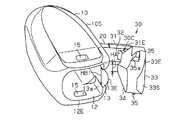
- FIG. 5 is a view similarly showing a perspective structure of the cord stopper, and is a perspective view of the cord stopper before the cap portion is fitted into the case portion, as viewed from the distal end side of the cord stopper.
- FIG. 2 is a view similarly showing the internal structure of the cord stopper, taken along the line AA in FIG. 1.
- FIG. 1 It is a figure which similarly shows the internal structure of a cord stopper, Comprising: (a) The figure which shows the state before a cap part is inserted by a case part, (b) The figure which shows the state by which a part of cap part was inserted by the case part (C) The figure which shows the state by which the whole cap part was engage
- a cap portion 30 is formed integrally with a case portion 10 having an elliptical cylinder shape via a hinge portion 20.
- a circular hole-shaped base end opening 11 as a small opening for inserting a cord into the cylinder of the case 10 is formed at one end of the case 10.
- a rectangular hole-shaped distal end opening portion 12 as a large opening portion for drawing a cord from the inside of the case portion 10 faces the base end opening portion 11. Is formed.
- the distal end opening portion 12 is used when the distal end of the cord inserted from the proximal end opening portion 11 is pulled out from the case portion 10.
- the size of the distal end opening 12 is larger than that of the proximal end opening 11 so that the drawn cord knot can be inserted therethrough.
- a guide slit 13 extending from the cylindrical end surface of the front end opening 12 toward the base end opening 11 is orthogonal to the outer surface of the cap connection wall 10S in the cap connection wall 10S which is the left wall of the peripheral wall of the case portion 10. It penetrates in the horizontal direction, which is the direction to do.
- the slit length L1 that is the length of the guide slit 13 is at least half the case length L2 that is the length of the case portion 10.
- the slit width HB1 that is the width of the guide slit 13 is constant over the entire extending direction of the guide slit 13.
- a strip-like hinge portion 20 extending in the extending direction is connected to the slit base end 13N on the base end opening 11 side of the guide slit 13.
- the wall thickness W which is the width in the lateral direction of the hinge portion 20, is constant throughout the extending direction of the hinge portion 20.
- the hinge width which is the width in the vertical direction of the hinge portion 20, is smaller than the slit width HB1 and is constant throughout the extending direction of the hinge portion 20.
- the overall shape and size of the hinge portion 20 is such that the hinge portion 20 can be accommodated in the guide slit 13.
- a belt-like connecting curved portion 31 that is a base end portion of the cap portion 30 is connected to the tip of the hinge portion 20.
- the connecting curved portion 31 has an outer surface continuous with the outer surface of the hinge portion 20, and an angle between the proximal end side of the connecting bent portion 31 and the distal end side of the connecting bent portion 31 is about 90 °. Further, it is gently bent from the tip of the hinge portion 20.
- the thickness of the connecting curved portion 31 in the horizontal direction is the same as the thickness W of the hinge portion 20 in the horizontal direction, and the connecting width HC1 which is the width in the vertical direction of the connecting curved portion 31 is the slit described above. It is substantially the same as the width HB1.
- a connecting portion contour 31E that is an outer edge in the longitudinal direction of the connecting curved portion 31 is formed in a shape that follows the slit contour 13E that is the inner edge of the guide slit 13.
- the overall shape and size of the connecting curved portion 31 are such that the entire connecting curved portion 31 can be fitted into the guide slit 13.
- the connecting curved portion 31 is fitted into the guide slit 13 so that the slit contour 13E and the connecting portion contour 31E described above coincide with each other.
- the outer peripheral surface of the part 10 is flush.
- a triangular plate-shaped connecting protrusion 32 is provided on the inner surface of the connecting bent portion 31 so as to extend inside the connecting bent portion 31.
- a rectangular parallelepiped blocking portion 33 constituting the cap portion 30 is connected to the distal end of the connecting curved portion 31 and the distal end of the connecting protrusion 32.
- the cap width HC2 that is the width in the vertical direction of the closing portion 33 is larger than the above-described connection width HC1 and is substantially the same as the opening width HB2 that is the width of the tip opening portion 12.
- the entire shape and size of the blocking portion 33 are such that the entire blocking portion 33 can be fitted into the hole of the tip opening portion 12.
- the closing portion 33 that is the distal end portion of the cap portion 30 is widened in the vertical direction from the connecting curved portion 31 that is the base end portion of the cap portion 30 and the connecting protrusion 32. Further, on the proximal end side of the closing portion 33, a locked surface 33 a is formed as a planar locked portion extending in the vertical direction from the distal end of the connecting curved portion 31 and the leading end of the connecting protrusion 32. . Thereby, between the to-be-latched surface 33a of the obstruction
- the closed portion contour 33 ⁇ / b> E that is the outer edge of the outer surface 33 ⁇ / b> S of the closed portion 33 is formed to follow the tip opening contour 12 ⁇ / b> E that is the inner edge of the tip opening portion 12.
- the tip opening contour 12 ⁇ / b> E and the blocking portion contour 33 ⁇ / b> E described above coincide with each other.
- the outer surface 33 ⁇ / b> S that closes the hole and the cylindrical end surface of the tip opening 12 are flush with each other.
- a rectangular pyramid-shaped insertion portion 34 that is tapered toward the inside of the case portion 10 at the tip of the closing portion 33 is formed.
- the insertion width HA which is the width in the longitudinal direction at the tip of the insertion portion 34, is smaller than the slit width HB1 described above. According to such a configuration, since the tip shape of the cap portion 30 is a tapered shape that can be inserted into the guide slit 13, when the closing portion 33 is fitted into the hole of the tip opening portion 12, It becomes easy for the insertion portion 34 which is the distal end portion to slide from the guide slit 13 and enter the distal end opening portion 12.
- a pair of upper and lower fitting projections 35 having a triangular prism shape project from both side surfaces of the closing portion 33 in the longitudinal direction along the longitudinal direction of the closing portion 33.
- An insertion surface 35 a that is flush with the case portion 10 side of the insertion portion 34 is formed on the surface of the fitting convex portion 35 on the case portion 10 side.
- the hole of the tip opening 12 in the case portion 10 is a hole that is expanded from the guide slit 13 toward the inside of the case portion 10, and the inner surface of the hole of the tip opening 12 and the guide slit are formed inside the case portion 10.
- a locking surface 13 a is formed as a locking portion having a step with the inner surface of 13. The locking surface 13a is engaged with the locked surface 33a described above by fitting the closing portion 33 described above into the hole of the tip opening portion 12.
- a pair of upper and lower fitting recesses 15 extending in the vertical direction pass through both side walls in the vertical direction of the peripheral wall of the case portion 10.
- Each of the pair of upper and lower fitting recesses 15 is fitted with the above-described pair of upper and lower fitting projections 35 by the above-described closing portion 33 being fitted into the hole of the tip opening 12.
- an internal space S that is expanded from the hole of the proximal end opening 11 to the inside of the case part 10 and communicates with the hole of the distal end opening 12 is formed inside the case part 10. Yes.
- a stepped portion 16 formed by the internal space S and the hole of the base end opening portion 11 is formed over the entire circumferential direction of the case portion 10.
- the hinge portion 20 is bent outside the guide slit 13 and the cap portion 30 is outside the guide slit 13. Placed in. From this state, the distal end of the string (not shown) is pulled out of the case portion 10 through the proximal end opening 11 and the distal end opening 12. Next, a knot is formed at the tip of the string, and then the string is pulled back from the proximal end opening 11. Thereby, the knot portion of the string comes into contact with the step portion 16 in the case portion 10 and cannot be pulled out from the proximal end opening portion 11.
- an external force directed from the closing portion 33 of the cap portion 30 toward the case portion 10 is applied to the closing portion 33 through a user's finger or the like.
- the external force acts on the closing portion 33
- the hinge portion 20 via the connecting curved portion 31, and thereby the hinge portion 20 is bent toward the inside of the case portion 10.
- the insertion portion 34 of the cap portion 30 first slides in a substantially lateral direction to guide slits. 13 At this time, as described above, since the insertion portion 34 is formed in a tapered shape, the insertion portion 34 can easily enter the guide slit 13. Subsequently, when the insertion portion 34 further enters the guide slit 13, the width of the guide slit 13 is expanded by the insertion portion 34, and then the closing portion 33 and the connecting curved portion 31 enter the guide slit 13.
- the closing portion 33 is fitted into the hole of the tip opening portion 12, the tip opening contour 12E and the blocking portion contour 33E coincide with each other, and the outer surface 33S that plugs the hole of the tip opening portion 12 in the blocking portion 33. And the end face of the tip opening 12 are flush with each other.
- a portion of the cap portion 30 that is exposed to the outside of the case portion 10 is prevented from being caught by an object outside the case portion 10 or being recognized by a tactile sensation such as a finger. It is possible to suppress the fitted cap portion 30 from being detached from the case portion 10.
- the blocking portion 33 is fitted into the hole of the tip opening 12, and the connecting curved portion 31 is fitted into the guide slit 13. That is, the entire cap portion 30 is fitted into the hole of the tip opening portion 12 and the guide slit 13. And in the hole of the front-end
- the portion of the cap portion 30 that is exposed to the outside of the tip opening portion 12 is prevented from being caught by an object outside the case portion 10 or recognized by a tactile sensation such as a finger. It is possible to suppress the fitted cap portion 30 from being detached from the case portion 10.
- the insertion portion 34 that is the tip of the cap portion 30 has a tapered shape that can be inserted into the guide slit 13. Therefore, when the cap portion 30 is fitted into the tip opening portion 12, it is easy to fit the insertion portion 34 from the guide slit 13 into the tip opening portion 12. As a result, when the cap part 30 is fitted into the tip opening part 12 as compared with the case where the cap part 30 is fitted into the tip opening part 12 along the direction in which the hole of the tip opening part 12 extends, the hinge part 20 is used. It is possible to reduce the angle of bending.
- a step portion 16 is formed between the internal space S of the case portion 10 and the hole of the proximal end opening portion 11.
- the knot portion of the string is easily locked to the step portion 16 between the internal space S of the case portion 10 and the hole of the proximal end opening portion 11. Therefore, it is possible to further suppress the tying portion of the string accommodated in the case portion 10 from coming out of the case portion 10.
- the cap part 30 is fitted in the case part 10 while sliding in the lateral direction, it is possible to reduce stress deformation in the hinge part 20.
- the said embodiment can also be changed and implemented as follows.
- the slit length L1 which is the sum of the length of the hinge part 20 and the length of the connecting curved part 31 may be less than half of the case length L2, and the shape, size and material of the hinge part 20 and the connecting curved part 31 may be used. Accordingly, it is appropriately selected. In short, it is sufficient that the length of the stress does not concentrate inside the hinge part 20 and the connecting curved part 31 in a state where the entire cap part 30 is fitted in the case part 10.
- the cap portion 30 can be fitted into the hole of the tip opening portion 12 along the direction in which the hole of the tip opening portion 12 extends.
- the aspect in which the cap part 30 is fitted into the hole of the distal end opening part 12 may be an aspect in which the cap part 30 is slid in the lateral direction according to the length of the hinge part 20, or the cap part 30 is extended. It may be a mode of sliding in the installation direction.
- the length in the extending direction of the hinge part 20 may be at least twice the wall thickness W of the hinge part 20 from the viewpoint that sufficient flexibility in the hinge part 20 is obtained. Depending on the length of the hinge part 20, it may be smaller than half of the case length L2. Even with such a configuration, it is possible to obtain the effects according to the above (1) to (7).
- a stepped portion 16 is formed which is a step between the hole of the proximal end opening 11 and the internal space S. Inside the case portion 10, the hole and the distal end of the proximal end opening 11 are formed.
- the hole 12 of the opening portion 12 may form a continuous surface, and the step portion 16 described above may be omitted.
- the small opening portion having a small hole in the pair of opening portions of the case portion 10 is configured so that the knot portion of the string housed inside the case portion cannot be pulled out from the inside of the case. . Even with such a configuration, it is possible to obtain the effects (1) to (6).
- the thickness W of the hinge part 20 may gradually increase from the proximal end of the hinge part 20 toward the distal end of the hinge part 20, or from the distal end of the hinge part 20 toward the proximal end of the hinge part 20. It may be configured to gradually increase. If the thickness W of the hinge part 20 is constant or changes gradually, it is possible to prevent the hinge part 20 from being broken by bending of the hinge part 20, and even with such a configuration, It is possible to obtain the effects according to the above (1) to (5).
- the number of the fitting recesses 15 and the number of the fitting projections 35 may be one or three or more, respectively, and even in such a configuration, the above (1) to (5) are applied. It is possible to obtain the effect. Even if the fitting concave portion 15 and the fitting convex portion 35 are omitted, it is possible to obtain the effects according to the above (1) to (4). By omitting the joint convex portion 35, the structure of the case portion 10 and the structure of the cap portion 30 can be simplified.
- the structure of the locking surface 13a and the structure of the locked surface 33a are the structures in which the locking surface 13a and the locked surface 33a are engaged by the cap portion 30 being fitted into the hole of the tip opening portion 12. If it is.
- the locking surface 13 a may be concave with respect to the surface of the guide slit 13, and the locked surface 33 a may be convex with respect to the surface of the connecting curved portion 31.
- the number of these locking parts and the number of the locked parts may be two or more. Even with such a configuration, it is possible to obtain the effects according to the above (1) to (4). Even when the locking portion and the locked portion are omitted, it is possible to obtain the effects according to the above (1) to (3). Is omitted, it is also possible to simplify the structure of the case portion 10 and the structure of the cap portion 30.
- the insertion portion 34 which is the tip of the cap portion 30 may be a flat plate extending in the lateral direction and the extending direction, or may be a tapered shape. In short, any shape may be used as long as the entire cap portion 30 is fitted into the hole of the tip opening portion 12 and the guide slit 13. Even with such a configuration, it is possible to obtain the effects according to the above (1) and (2). In addition, if the portion facing the inside of the case portion 10 is a tapered shape, it is easy to prevent the cap portion 30 from being detached from the hole of the tip opening portion 12 and the guide slit 13. It should be noted that the entire contents of the specification, claims, drawings and abstract of Japanese Patent Application No. 2011-084316 filed on April 6, 2011 are cited here as disclosure of the specification of the present invention. Incorporate.
Landscapes
- Engineering & Computer Science (AREA)
- General Engineering & Computer Science (AREA)
- Mechanical Engineering (AREA)
- Closures For Containers (AREA)
- Buckles (AREA)
- Cartons (AREA)
Abstract
L'invention porte sur un dispositif d'arrêt de câble, lequel dispositif comprend une fente de guidage qui perce une paroi périphérique externe d'un boîtier, qui communique avec un trou dans une section d'ouverture de pointe, et qui s'étend à partir d'une face d'extrémité cylindrique de la section d'ouverture de pointe vers un côté de section d'ouverture d'extrémité de base. Une section de charnière en forme de bande s'étendant à partir de la section d'extrémité sur le côté de section d'ouverture d'extrémité de base dans la fente de guidage vers le côté de section d'ouverture de pointe est reliée à ladite section d'extrémité. L'ensemble d'une section de capuchon est inséré dans le trou de section d'ouverture de pointe et la fente de guidage, et une partie de surface externe de la section de capuchon bouchant le trou de section d'ouverture de pointe a la même surface que la face d'extrémité cylindrique de la section d'ouverture de pointe.
Priority Applications (1)
| Application Number | Priority Date | Filing Date | Title |
|---|---|---|---|
| CN201280027704.7A CN103607922B (zh) | 2011-04-06 | 2012-04-04 | 绳固定器 |
Applications Claiming Priority (2)
| Application Number | Priority Date | Filing Date | Title |
|---|---|---|---|
| JP2011-084316 | 2011-04-06 | ||
| JP2011084316A JP2012217540A (ja) | 2011-04-06 | 2011-04-06 | コードストッパー |
Publications (1)
| Publication Number | Publication Date |
|---|---|
| WO2012137835A1 true WO2012137835A1 (fr) | 2012-10-11 |
Family
ID=46969229
Family Applications (1)
| Application Number | Title | Priority Date | Filing Date |
|---|---|---|---|
| PCT/JP2012/059237 Ceased WO2012137835A1 (fr) | 2011-04-06 | 2012-04-04 | Dispositif d'arrêt de câble |
Country Status (4)
| Country | Link |
|---|---|
| JP (1) | JP2012217540A (fr) |
| CN (1) | CN103607922B (fr) |
| TW (1) | TWI508678B (fr) |
| WO (1) | WO2012137835A1 (fr) |
Families Citing this family (1)
| Publication number | Priority date | Publication date | Assignee | Title |
|---|---|---|---|---|
| EP3162231B1 (fr) | 2015-10-29 | 2018-04-18 | Globeride, Inc. | Capuche pour vêtement et vêtement à capuche |
Citations (2)
| Publication number | Priority date | Publication date | Assignee | Title |
|---|---|---|---|---|
| JPH01154813U (fr) * | 1988-04-11 | 1989-10-25 | ||
| JPH1199008A (ja) * | 1997-09-30 | 1999-04-13 | Nifco Inc | 紐類の端部カバー |
Family Cites Families (2)
| Publication number | Priority date | Publication date | Assignee | Title |
|---|---|---|---|---|
| JP3262455B2 (ja) * | 1994-05-27 | 2002-03-04 | 株式会社ニフコ | 紐止め具 |
| JP3958854B2 (ja) * | 1997-12-26 | 2007-08-15 | 株式会社ニフコ | 帯、紐状体の端末カバー |
-
2011
- 2011-04-06 JP JP2011084316A patent/JP2012217540A/ja not_active Withdrawn
-
2012
- 2012-04-04 WO PCT/JP2012/059237 patent/WO2012137835A1/fr not_active Ceased
- 2012-04-04 CN CN201280027704.7A patent/CN103607922B/zh active Active
- 2012-04-05 TW TW101112017A patent/TWI508678B/zh active
Patent Citations (2)
| Publication number | Priority date | Publication date | Assignee | Title |
|---|---|---|---|---|
| JPH01154813U (fr) * | 1988-04-11 | 1989-10-25 | ||
| JPH1199008A (ja) * | 1997-09-30 | 1999-04-13 | Nifco Inc | 紐類の端部カバー |
Also Published As
| Publication number | Publication date |
|---|---|
| TW201247120A (en) | 2012-12-01 |
| TWI508678B (zh) | 2015-11-21 |
| CN103607922B (zh) | 2016-03-02 |
| CN103607922A (zh) | 2014-02-26 |
| JP2012217540A (ja) | 2012-11-12 |
Similar Documents
| Publication | Publication Date | Title |
|---|---|---|
| JP5701593B2 (ja) | 2ピースクリップ | |
| US8196338B2 (en) | Fishing line stop having a channel offset | |
| TWI528912B (zh) | buckle | |
| JP2017512512A5 (fr) | ||
| JP2022000243A5 (fr) | ||
| US20090297250A1 (en) | Pen cap and pen barrel coupling structure | |
| TW201632104A (zh) | 用於提升抗扭強度的拉鍊頭組合結構及其滑動件 | |
| US8813321B2 (en) | Buckle | |
| JP2012217540A (ja) | コードストッパー | |
| US20110283486A1 (en) | Adapter for attachment to an elastic cord for coupling accessories | |
| JP2022506391A5 (fr) | ||
| JP5796541B2 (ja) | ワイヤーハーネス固定具 | |
| JP4825161B2 (ja) | なす環 | |
| TWI507144B (zh) | Rope head member | |
| JP6176954B2 (ja) | セグメント連結継手、及び、セグメント | |
| JP6355287B1 (ja) | 弾性継ぎ手 | |
| JP5944105B2 (ja) | 紐留め具 | |
| US9689414B2 (en) | Fastening device for installing a fitting in a holed thin wall | |
| KR200400908Y1 (ko) | 미니 스프링클러용 관연결구 | |
| US9512862B2 (en) | Fastener | |
| JP6683948B2 (ja) | サドル | |
| JP2013104537A (ja) | 取付具 | |
| KR200479755Y1 (ko) | 드레인 플러그 | |
| JP6133067B2 (ja) | スプール連結具及びこれを備えたスプール | |
| JP5836022B2 (ja) | バックル |
Legal Events
| Date | Code | Title | Description |
|---|---|---|---|
| 121 | Ep: the epo has been informed by wipo that ep was designated in this application |
Ref document number: 12767585 Country of ref document: EP Kind code of ref document: A1 |
|
| NENP | Non-entry into the national phase |
Ref country code: DE |
|
| 122 | Ep: pct application non-entry in european phase |
Ref document number: 12767585 Country of ref document: EP Kind code of ref document: A1 |