WO2012137929A1 - Dispositif et procédé de production d'une électrode ensachée - Google Patents
Dispositif et procédé de production d'une électrode ensachée Download PDFInfo
- Publication number
- WO2012137929A1 WO2012137929A1 PCT/JP2012/059543 JP2012059543W WO2012137929A1 WO 2012137929 A1 WO2012137929 A1 WO 2012137929A1 JP 2012059543 W JP2012059543 W JP 2012059543W WO 2012137929 A1 WO2012137929 A1 WO 2012137929A1
- Authority
- WO
- WIPO (PCT)
- Prior art keywords
- separators
- electrode
- pair
- joining
- separator
- Prior art date
- Legal status (The legal status is an assumption and is not a legal conclusion. Google has not performed a legal analysis and makes no representation as to the accuracy of the status listed.)
- Ceased
Links
Images




Classifications
-
- H—ELECTRICITY
- H01—ELECTRIC ELEMENTS
- H01M—PROCESSES OR MEANS, e.g. BATTERIES, FOR THE DIRECT CONVERSION OF CHEMICAL ENERGY INTO ELECTRICAL ENERGY
- H01M10/00—Secondary cells; Manufacture thereof
- H01M10/05—Accumulators with non-aqueous electrolyte
- H01M10/058—Construction or manufacture
- H01M10/0585—Construction or manufacture of accumulators having only flat construction elements, i.e. flat positive electrodes, flat negative electrodes and flat separators
-
- H—ELECTRICITY
- H01—ELECTRIC ELEMENTS
- H01M—PROCESSES OR MEANS, e.g. BATTERIES, FOR THE DIRECT CONVERSION OF CHEMICAL ENERGY INTO ELECTRICAL ENERGY
- H01M10/00—Secondary cells; Manufacture thereof
- H01M10/04—Construction or manufacture in general
- H01M10/0404—Machines for assembling batteries
-
- B—PERFORMING OPERATIONS; TRANSPORTING
- B29—WORKING OF PLASTICS; WORKING OF SUBSTANCES IN A PLASTIC STATE IN GENERAL
- B29C—SHAPING OR JOINING OF PLASTICS; SHAPING OF MATERIAL IN A PLASTIC STATE, NOT OTHERWISE PROVIDED FOR; AFTER-TREATMENT OF THE SHAPED PRODUCTS, e.g. REPAIRING
- B29C65/00—Joining or sealing of preformed parts, e.g. welding of plastics materials; Apparatus therefor
- B29C65/02—Joining or sealing of preformed parts, e.g. welding of plastics materials; Apparatus therefor by heating, with or without pressure
- B29C65/18—Joining or sealing of preformed parts, e.g. welding of plastics materials; Apparatus therefor by heating, with or without pressure using heated tools
-
- B—PERFORMING OPERATIONS; TRANSPORTING
- B29—WORKING OF PLASTICS; WORKING OF SUBSTANCES IN A PLASTIC STATE IN GENERAL
- B29C—SHAPING OR JOINING OF PLASTICS; SHAPING OF MATERIAL IN A PLASTIC STATE, NOT OTHERWISE PROVIDED FOR; AFTER-TREATMENT OF THE SHAPED PRODUCTS, e.g. REPAIRING
- B29C65/00—Joining or sealing of preformed parts, e.g. welding of plastics materials; Apparatus therefor
- B29C65/48—Joining or sealing of preformed parts, e.g. welding of plastics materials; Apparatus therefor using adhesives, i.e. using supplementary joining material; solvent bonding
-
- B—PERFORMING OPERATIONS; TRANSPORTING
- B29—WORKING OF PLASTICS; WORKING OF SUBSTANCES IN A PLASTIC STATE IN GENERAL
- B29C—SHAPING OR JOINING OF PLASTICS; SHAPING OF MATERIAL IN A PLASTIC STATE, NOT OTHERWISE PROVIDED FOR; AFTER-TREATMENT OF THE SHAPED PRODUCTS, e.g. REPAIRING
- B29C65/00—Joining or sealing of preformed parts, e.g. welding of plastics materials; Apparatus therefor
- B29C65/56—Joining or sealing of preformed parts, e.g. welding of plastics materials; Apparatus therefor using mechanical means or mechanical connections, e.g. form-fits
-
- B—PERFORMING OPERATIONS; TRANSPORTING
- B29—WORKING OF PLASTICS; WORKING OF SUBSTANCES IN A PLASTIC STATE IN GENERAL
- B29C—SHAPING OR JOINING OF PLASTICS; SHAPING OF MATERIAL IN A PLASTIC STATE, NOT OTHERWISE PROVIDED FOR; AFTER-TREATMENT OF THE SHAPED PRODUCTS, e.g. REPAIRING
- B29C65/00—Joining or sealing of preformed parts, e.g. welding of plastics materials; Apparatus therefor
- B29C65/78—Means for handling the parts to be joined, e.g. for making containers or hollow articles, e.g. means for handling sheets, plates, web-like materials, tubular articles, hollow articles or elements to be joined therewith; Means for discharging the joined articles from the joining apparatus
- B29C65/7841—Holding or clamping means for handling purposes
-
- B—PERFORMING OPERATIONS; TRANSPORTING
- B29—WORKING OF PLASTICS; WORKING OF SUBSTANCES IN A PLASTIC STATE IN GENERAL
- B29C—SHAPING OR JOINING OF PLASTICS; SHAPING OF MATERIAL IN A PLASTIC STATE, NOT OTHERWISE PROVIDED FOR; AFTER-TREATMENT OF THE SHAPED PRODUCTS, e.g. REPAIRING
- B29C65/00—Joining or sealing of preformed parts, e.g. welding of plastics materials; Apparatus therefor
- B29C65/78—Means for handling the parts to be joined, e.g. for making containers or hollow articles, e.g. means for handling sheets, plates, web-like materials, tubular articles, hollow articles or elements to be joined therewith; Means for discharging the joined articles from the joining apparatus
- B29C65/7841—Holding or clamping means for handling purposes
- B29C65/7847—Holding or clamping means for handling purposes using vacuum to hold at least one of the parts to be joined
-
- B—PERFORMING OPERATIONS; TRANSPORTING
- B29—WORKING OF PLASTICS; WORKING OF SUBSTANCES IN A PLASTIC STATE IN GENERAL
- B29C—SHAPING OR JOINING OF PLASTICS; SHAPING OF MATERIAL IN A PLASTIC STATE, NOT OTHERWISE PROVIDED FOR; AFTER-TREATMENT OF THE SHAPED PRODUCTS, e.g. REPAIRING
- B29C65/00—Joining or sealing of preformed parts, e.g. welding of plastics materials; Apparatus therefor
- B29C65/78—Means for handling the parts to be joined, e.g. for making containers or hollow articles, e.g. means for handling sheets, plates, web-like materials, tubular articles, hollow articles or elements to be joined therewith; Means for discharging the joined articles from the joining apparatus
- B29C65/7841—Holding or clamping means for handling purposes
- B29C65/7852—Holding or clamping means for handling purposes using electrostatic forces to hold at least one of the parts to be joined
-
- B—PERFORMING OPERATIONS; TRANSPORTING
- B29—WORKING OF PLASTICS; WORKING OF SUBSTANCES IN A PLASTIC STATE IN GENERAL
- B29C—SHAPING OR JOINING OF PLASTICS; SHAPING OF MATERIAL IN A PLASTIC STATE, NOT OTHERWISE PROVIDED FOR; AFTER-TREATMENT OF THE SHAPED PRODUCTS, e.g. REPAIRING
- B29C65/00—Joining or sealing of preformed parts, e.g. welding of plastics materials; Apparatus therefor
- B29C65/78—Means for handling the parts to be joined, e.g. for making containers or hollow articles, e.g. means for handling sheets, plates, web-like materials, tubular articles, hollow articles or elements to be joined therewith; Means for discharging the joined articles from the joining apparatus
- B29C65/7858—Means for handling the parts to be joined, e.g. for making containers or hollow articles, e.g. means for handling sheets, plates, web-like materials, tubular articles, hollow articles or elements to be joined therewith; Means for discharging the joined articles from the joining apparatus characterised by the feeding movement of the parts to be joined
- B29C65/7888—Means for handling of moving sheets or webs
- B29C65/7894—Means for handling of moving sheets or webs of continuously moving sheets or webs
-
- B—PERFORMING OPERATIONS; TRANSPORTING
- B29—WORKING OF PLASTICS; WORKING OF SUBSTANCES IN A PLASTIC STATE IN GENERAL
- B29C—SHAPING OR JOINING OF PLASTICS; SHAPING OF MATERIAL IN A PLASTIC STATE, NOT OTHERWISE PROVIDED FOR; AFTER-TREATMENT OF THE SHAPED PRODUCTS, e.g. REPAIRING
- B29C65/00—Joining or sealing of preformed parts, e.g. welding of plastics materials; Apparatus therefor
- B29C65/78—Means for handling the parts to be joined, e.g. for making containers or hollow articles, e.g. means for handling sheets, plates, web-like materials, tubular articles, hollow articles or elements to be joined therewith; Means for discharging the joined articles from the joining apparatus
- B29C65/80—Rotatable transfer means for loading or unloading purposes, i.e. turret transfer means
-
- B—PERFORMING OPERATIONS; TRANSPORTING
- B29—WORKING OF PLASTICS; WORKING OF SUBSTANCES IN A PLASTIC STATE IN GENERAL
- B29C—SHAPING OR JOINING OF PLASTICS; SHAPING OF MATERIAL IN A PLASTIC STATE, NOT OTHERWISE PROVIDED FOR; AFTER-TREATMENT OF THE SHAPED PRODUCTS, e.g. REPAIRING
- B29C66/00—General aspects of processes or apparatus for joining preformed parts
- B29C66/01—General aspects dealing with the joint area or with the area to be joined
- B29C66/05—Particular design of joint configurations
- B29C66/10—Particular design of joint configurations particular design of the joint cross-sections
- B29C66/11—Joint cross-sections comprising a single joint-segment, i.e. one of the parts to be joined comprising a single joint-segment in the joint cross-section
- B29C66/112—Single lapped joints
- B29C66/1122—Single lap to lap joints, i.e. overlap joints
-
- B—PERFORMING OPERATIONS; TRANSPORTING
- B29—WORKING OF PLASTICS; WORKING OF SUBSTANCES IN A PLASTIC STATE IN GENERAL
- B29C—SHAPING OR JOINING OF PLASTICS; SHAPING OF MATERIAL IN A PLASTIC STATE, NOT OTHERWISE PROVIDED FOR; AFTER-TREATMENT OF THE SHAPED PRODUCTS, e.g. REPAIRING
- B29C66/00—General aspects of processes or apparatus for joining preformed parts
- B29C66/01—General aspects dealing with the joint area or with the area to be joined
- B29C66/05—Particular design of joint configurations
- B29C66/20—Particular design of joint configurations particular design of the joint lines, e.g. of the weld lines
- B29C66/21—Particular design of joint configurations particular design of the joint lines, e.g. of the weld lines said joint lines being formed by a single dot or dash or by several dots or dashes, i.e. spot joining or spot welding
-
- B—PERFORMING OPERATIONS; TRANSPORTING
- B29—WORKING OF PLASTICS; WORKING OF SUBSTANCES IN A PLASTIC STATE IN GENERAL
- B29C—SHAPING OR JOINING OF PLASTICS; SHAPING OF MATERIAL IN A PLASTIC STATE, NOT OTHERWISE PROVIDED FOR; AFTER-TREATMENT OF THE SHAPED PRODUCTS, e.g. REPAIRING
- B29C66/00—General aspects of processes or apparatus for joining preformed parts
- B29C66/40—General aspects of joining substantially flat articles, e.g. plates, sheets or web-like materials; Making flat seams in tubular or hollow articles; Joining single elements to substantially flat surfaces
- B29C66/41—Joining substantially flat articles ; Making flat seams in tubular or hollow articles
- B29C66/43—Joining a relatively small portion of the surface of said articles
- B29C66/433—Casing-in, i.e. enclosing an element between two sheets by an outlined seam
-
- B—PERFORMING OPERATIONS; TRANSPORTING
- B29—WORKING OF PLASTICS; WORKING OF SUBSTANCES IN A PLASTIC STATE IN GENERAL
- B29C—SHAPING OR JOINING OF PLASTICS; SHAPING OF MATERIAL IN A PLASTIC STATE, NOT OTHERWISE PROVIDED FOR; AFTER-TREATMENT OF THE SHAPED PRODUCTS, e.g. REPAIRING
- B29C66/00—General aspects of processes or apparatus for joining preformed parts
- B29C66/80—General aspects of machine operations or constructions and parts thereof
- B29C66/81—General aspects of the pressing elements, i.e. the elements applying pressure on the parts to be joined in the area to be joined, e.g. the welding jaws or clamps
- B29C66/814—General aspects of the pressing elements, i.e. the elements applying pressure on the parts to be joined in the area to be joined, e.g. the welding jaws or clamps characterised by the design of the pressing elements, e.g. of the welding jaws or clamps
- B29C66/8141—General aspects of the pressing elements, i.e. the elements applying pressure on the parts to be joined in the area to be joined, e.g. the welding jaws or clamps characterised by the design of the pressing elements, e.g. of the welding jaws or clamps characterised by the surface geometry of the part of the pressing elements, e.g. welding jaws or clamps, coming into contact with the parts to be joined
- B29C66/81427—General aspects of the pressing elements, i.e. the elements applying pressure on the parts to be joined in the area to be joined, e.g. the welding jaws or clamps characterised by the design of the pressing elements, e.g. of the welding jaws or clamps characterised by the surface geometry of the part of the pressing elements, e.g. welding jaws or clamps, coming into contact with the parts to be joined comprising a single ridge, e.g. for making a weakening line; comprising a single tooth
- B29C66/81429—General aspects of the pressing elements, i.e. the elements applying pressure on the parts to be joined in the area to be joined, e.g. the welding jaws or clamps characterised by the design of the pressing elements, e.g. of the welding jaws or clamps characterised by the surface geometry of the part of the pressing elements, e.g. welding jaws or clamps, coming into contact with the parts to be joined comprising a single ridge, e.g. for making a weakening line; comprising a single tooth comprising a single tooth
-
- B—PERFORMING OPERATIONS; TRANSPORTING
- B29—WORKING OF PLASTICS; WORKING OF SUBSTANCES IN A PLASTIC STATE IN GENERAL
- B29C—SHAPING OR JOINING OF PLASTICS; SHAPING OF MATERIAL IN A PLASTIC STATE, NOT OTHERWISE PROVIDED FOR; AFTER-TREATMENT OF THE SHAPED PRODUCTS, e.g. REPAIRING
- B29C66/00—General aspects of processes or apparatus for joining preformed parts
- B29C66/80—General aspects of machine operations or constructions and parts thereof
- B29C66/81—General aspects of the pressing elements, i.e. the elements applying pressure on the parts to be joined in the area to be joined, e.g. the welding jaws or clamps
- B29C66/816—General aspects of the pressing elements, i.e. the elements applying pressure on the parts to be joined in the area to be joined, e.g. the welding jaws or clamps characterised by the mounting of the pressing elements, e.g. of the welding jaws or clamps
- B29C66/8161—General aspects of the pressing elements, i.e. the elements applying pressure on the parts to be joined in the area to be joined, e.g. the welding jaws or clamps characterised by the mounting of the pressing elements, e.g. of the welding jaws or clamps said pressing elements being supported or backed-up by springs or by resilient material
-
- B—PERFORMING OPERATIONS; TRANSPORTING
- B29—WORKING OF PLASTICS; WORKING OF SUBSTANCES IN A PLASTIC STATE IN GENERAL
- B29C—SHAPING OR JOINING OF PLASTICS; SHAPING OF MATERIAL IN A PLASTIC STATE, NOT OTHERWISE PROVIDED FOR; AFTER-TREATMENT OF THE SHAPED PRODUCTS, e.g. REPAIRING
- B29C66/00—General aspects of processes or apparatus for joining preformed parts
- B29C66/80—General aspects of machine operations or constructions and parts thereof
- B29C66/81—General aspects of the pressing elements, i.e. the elements applying pressure on the parts to be joined in the area to be joined, e.g. the welding jaws or clamps
- B29C66/818—General aspects of the pressing elements, i.e. the elements applying pressure on the parts to be joined in the area to be joined, e.g. the welding jaws or clamps characterised by the cooling constructional aspects, or by the thermal or electrical insulating or conducting constructional aspects of the welding jaws or of the clamps ; comprising means for compensating for the thermal expansion of the welding jaws or of the clamps
- B29C66/8181—General aspects of the pressing elements, i.e. the elements applying pressure on the parts to be joined in the area to be joined, e.g. the welding jaws or clamps characterised by the cooling constructional aspects, or by the thermal or electrical insulating or conducting constructional aspects of the welding jaws or of the clamps ; comprising means for compensating for the thermal expansion of the welding jaws or of the clamps characterised by the cooling constructional aspects
- B29C66/81815—General aspects of the pressing elements, i.e. the elements applying pressure on the parts to be joined in the area to be joined, e.g. the welding jaws or clamps characterised by the cooling constructional aspects, or by the thermal or electrical insulating or conducting constructional aspects of the welding jaws or of the clamps ; comprising means for compensating for the thermal expansion of the welding jaws or of the clamps characterised by the cooling constructional aspects of the clamps
-
- B—PERFORMING OPERATIONS; TRANSPORTING
- B29—WORKING OF PLASTICS; WORKING OF SUBSTANCES IN A PLASTIC STATE IN GENERAL
- B29C—SHAPING OR JOINING OF PLASTICS; SHAPING OF MATERIAL IN A PLASTIC STATE, NOT OTHERWISE PROVIDED FOR; AFTER-TREATMENT OF THE SHAPED PRODUCTS, e.g. REPAIRING
- B29C66/00—General aspects of processes or apparatus for joining preformed parts
- B29C66/80—General aspects of machine operations or constructions and parts thereof
- B29C66/83—General aspects of machine operations or constructions and parts thereof characterised by the movement of the joining or pressing tools
- B29C66/834—General aspects of machine operations or constructions and parts thereof characterised by the movement of the joining or pressing tools moving with the parts to be joined
- B29C66/8351—Jaws mounted on rollers, cylinders, drums, bands, belts or chains; Flying jaws
- B29C66/83541—Jaws mounted on rollers, cylinders, drums, bands, belts or chains; Flying jaws flying jaws, e.g. jaws mounted on crank mechanisms or following a hand over hand movement
- B29C66/83543—Jaws mounted on rollers, cylinders, drums, bands, belts or chains; Flying jaws flying jaws, e.g. jaws mounted on crank mechanisms or following a hand over hand movement cooperating flying jaws
-
- B—PERFORMING OPERATIONS; TRANSPORTING
- B29—WORKING OF PLASTICS; WORKING OF SUBSTANCES IN A PLASTIC STATE IN GENERAL
- B29C—SHAPING OR JOINING OF PLASTICS; SHAPING OF MATERIAL IN A PLASTIC STATE, NOT OTHERWISE PROVIDED FOR; AFTER-TREATMENT OF THE SHAPED PRODUCTS, e.g. REPAIRING
- B29C66/00—General aspects of processes or apparatus for joining preformed parts
- B29C66/90—Measuring or controlling the joining process
- B29C66/91—Measuring or controlling the joining process by measuring or controlling the temperature, the heat or the thermal flux
- B29C66/914—Measuring or controlling the joining process by measuring or controlling the temperature, the heat or the thermal flux by controlling or regulating the temperature, the heat or the thermal flux
- B29C66/9141—Measuring or controlling the joining process by measuring or controlling the temperature, the heat or the thermal flux by controlling or regulating the temperature, the heat or the thermal flux by controlling or regulating the temperature
- B29C66/91421—Measuring or controlling the joining process by measuring or controlling the temperature, the heat or the thermal flux by controlling or regulating the temperature, the heat or the thermal flux by controlling or regulating the temperature of the joining tools
-
- B—PERFORMING OPERATIONS; TRANSPORTING
- B29—WORKING OF PLASTICS; WORKING OF SUBSTANCES IN A PLASTIC STATE IN GENERAL
- B29C—SHAPING OR JOINING OF PLASTICS; SHAPING OF MATERIAL IN A PLASTIC STATE, NOT OTHERWISE PROVIDED FOR; AFTER-TREATMENT OF THE SHAPED PRODUCTS, e.g. REPAIRING
- B29C66/00—General aspects of processes or apparatus for joining preformed parts
- B29C66/90—Measuring or controlling the joining process
- B29C66/93—Measuring or controlling the joining process by measuring or controlling the speed
- B29C66/934—Measuring or controlling the joining process by measuring or controlling the speed by controlling or regulating the speed
- B29C66/93441—Measuring or controlling the joining process by measuring or controlling the speed by controlling or regulating the speed the speed being non-constant over time
-
- B—PERFORMING OPERATIONS; TRANSPORTING
- B29—WORKING OF PLASTICS; WORKING OF SUBSTANCES IN A PLASTIC STATE IN GENERAL
- B29C—SHAPING OR JOINING OF PLASTICS; SHAPING OF MATERIAL IN A PLASTIC STATE, NOT OTHERWISE PROVIDED FOR; AFTER-TREATMENT OF THE SHAPED PRODUCTS, e.g. REPAIRING
- B29C66/00—General aspects of processes or apparatus for joining preformed parts
- B29C66/90—Measuring or controlling the joining process
- B29C66/93—Measuring or controlling the joining process by measuring or controlling the speed
- B29C66/939—Measuring or controlling the joining process by measuring or controlling the speed characterised by specific speed values or ranges
- B29C66/9392—Measuring or controlling the joining process by measuring or controlling the speed characterised by specific speed values or ranges in explicit relation to another variable, e.g. speed diagrams
-
- H—ELECTRICITY
- H01—ELECTRIC ELEMENTS
- H01M—PROCESSES OR MEANS, e.g. BATTERIES, FOR THE DIRECT CONVERSION OF CHEMICAL ENERGY INTO ELECTRICAL ENERGY
- H01M10/00—Secondary cells; Manufacture thereof
- H01M10/04—Construction or manufacture in general
- H01M10/0413—Large-sized flat cells or batteries for motive or stationary systems with plate-like electrodes
-
- H—ELECTRICITY
- H01—ELECTRIC ELEMENTS
- H01M—PROCESSES OR MEANS, e.g. BATTERIES, FOR THE DIRECT CONVERSION OF CHEMICAL ENERGY INTO ELECTRICAL ENERGY
- H01M10/00—Secondary cells; Manufacture thereof
- H01M10/04—Construction or manufacture in general
- H01M10/0436—Small-sized flat cells or batteries for portable equipment
-
- H—ELECTRICITY
- H01—ELECTRIC ELEMENTS
- H01M—PROCESSES OR MEANS, e.g. BATTERIES, FOR THE DIRECT CONVERSION OF CHEMICAL ENERGY INTO ELECTRICAL ENERGY
- H01M4/00—Electrodes
- H01M4/02—Electrodes composed of, or comprising, active material
- H01M4/04—Processes of manufacture in general
-
- H—ELECTRICITY
- H01—ELECTRIC ELEMENTS
- H01M—PROCESSES OR MEANS, e.g. BATTERIES, FOR THE DIRECT CONVERSION OF CHEMICAL ENERGY INTO ELECTRICAL ENERGY
- H01M50/00—Constructional details or processes of manufacture of the non-active parts of electrochemical cells other than fuel cells, e.g. hybrid cells
- H01M50/40—Separators; Membranes; Diaphragms; Spacing elements inside cells
- H01M50/403—Manufacturing processes of separators, membranes or diaphragms
-
- H—ELECTRICITY
- H01—ELECTRIC ELEMENTS
- H01M—PROCESSES OR MEANS, e.g. BATTERIES, FOR THE DIRECT CONVERSION OF CHEMICAL ENERGY INTO ELECTRICAL ENERGY
- H01M50/00—Constructional details or processes of manufacture of the non-active parts of electrochemical cells other than fuel cells, e.g. hybrid cells
- H01M50/40—Separators; Membranes; Diaphragms; Spacing elements inside cells
- H01M50/46—Separators, membranes or diaphragms characterised by their combination with electrodes
-
- H—ELECTRICITY
- H01—ELECTRIC ELEMENTS
- H01M—PROCESSES OR MEANS, e.g. BATTERIES, FOR THE DIRECT CONVERSION OF CHEMICAL ENERGY INTO ELECTRICAL ENERGY
- H01M50/00—Constructional details or processes of manufacture of the non-active parts of electrochemical cells other than fuel cells, e.g. hybrid cells
- H01M50/40—Separators; Membranes; Diaphragms; Spacing elements inside cells
- H01M50/463—Separators, membranes or diaphragms characterised by their shape
-
- B—PERFORMING OPERATIONS; TRANSPORTING
- B29—WORKING OF PLASTICS; WORKING OF SUBSTANCES IN A PLASTIC STATE IN GENERAL
- B29K—INDEXING SCHEME ASSOCIATED WITH SUBCLASSES B29B, B29C OR B29D, RELATING TO MOULDING MATERIALS OR TO MATERIALS FOR MOULDS, REINFORCEMENTS, FILLERS OR PREFORMED PARTS, e.g. INSERTS
- B29K2705/00—Use of metals, their alloys or their compounds, for preformed parts, e.g. for inserts
-
- B—PERFORMING OPERATIONS; TRANSPORTING
- B29—WORKING OF PLASTICS; WORKING OF SUBSTANCES IN A PLASTIC STATE IN GENERAL
- B29L—INDEXING SCHEME ASSOCIATED WITH SUBCLASS B29C, RELATING TO PARTICULAR ARTICLES
- B29L2031/00—Other particular articles
- B29L2031/34—Electrical apparatus, e.g. sparking plugs or parts thereof
- B29L2031/3468—Batteries, accumulators or fuel cells
-
- Y—GENERAL TAGGING OF NEW TECHNOLOGICAL DEVELOPMENTS; GENERAL TAGGING OF CROSS-SECTIONAL TECHNOLOGIES SPANNING OVER SEVERAL SECTIONS OF THE IPC; TECHNICAL SUBJECTS COVERED BY FORMER USPC CROSS-REFERENCE ART COLLECTIONS [XRACs] AND DIGESTS
- Y02—TECHNOLOGIES OR APPLICATIONS FOR MITIGATION OR ADAPTATION AGAINST CLIMATE CHANGE
- Y02E—REDUCTION OF GREENHOUSE GAS [GHG] EMISSIONS, RELATED TO ENERGY GENERATION, TRANSMISSION OR DISTRIBUTION
- Y02E60/00—Enabling technologies; Technologies with a potential or indirect contribution to GHG emissions mitigation
- Y02E60/10—Energy storage using batteries
-
- Y—GENERAL TAGGING OF NEW TECHNOLOGICAL DEVELOPMENTS; GENERAL TAGGING OF CROSS-SECTIONAL TECHNOLOGIES SPANNING OVER SEVERAL SECTIONS OF THE IPC; TECHNICAL SUBJECTS COVERED BY FORMER USPC CROSS-REFERENCE ART COLLECTIONS [XRACs] AND DIGESTS
- Y02—TECHNOLOGIES OR APPLICATIONS FOR MITIGATION OR ADAPTATION AGAINST CLIMATE CHANGE
- Y02P—CLIMATE CHANGE MITIGATION TECHNOLOGIES IN THE PRODUCTION OR PROCESSING OF GOODS
- Y02P70/00—Climate change mitigation technologies in the production process for final industrial or consumer products
- Y02P70/50—Manufacturing or production processes characterised by the final manufactured product
-
- Y—GENERAL TAGGING OF NEW TECHNOLOGICAL DEVELOPMENTS; GENERAL TAGGING OF CROSS-SECTIONAL TECHNOLOGIES SPANNING OVER SEVERAL SECTIONS OF THE IPC; TECHNICAL SUBJECTS COVERED BY FORMER USPC CROSS-REFERENCE ART COLLECTIONS [XRACs] AND DIGESTS
- Y10—TECHNICAL SUBJECTS COVERED BY FORMER USPC
- Y10T—TECHNICAL SUBJECTS COVERED BY FORMER US CLASSIFICATION
- Y10T29/00—Metal working
- Y10T29/49—Method of mechanical manufacture
- Y10T29/49002—Electrical device making
- Y10T29/49108—Electric battery cell making
-
- Y—GENERAL TAGGING OF NEW TECHNOLOGICAL DEVELOPMENTS; GENERAL TAGGING OF CROSS-SECTIONAL TECHNOLOGIES SPANNING OVER SEVERAL SECTIONS OF THE IPC; TECHNICAL SUBJECTS COVERED BY FORMER USPC CROSS-REFERENCE ART COLLECTIONS [XRACs] AND DIGESTS
- Y10—TECHNICAL SUBJECTS COVERED BY FORMER USPC
- Y10T—TECHNICAL SUBJECTS COVERED BY FORMER US CLASSIFICATION
- Y10T29/00—Metal working
- Y10T29/53—Means to assemble or disassemble
- Y10T29/5313—Means to assemble electrical device
- Y10T29/53135—Storage cell or battery
Definitions
- the present invention relates to a device for manufacturing a packaged electrode and a method for manufacturing a packaged electrode.
- Patent Document 1 A packaged electrode in which an electrode is packaged between a pair of separators is known.
- Patent Document 1 has a problem that the cycle time becomes long.
- the object of the present invention is to reduce the cycle time required to pack an electrode between a pair of separators, thereby improving the efficiency of manufacturing the packed electrode, thereby contributing to the efficiency of manufacturing the entire battery.
- An object of the present invention is to provide a packaged electrode manufacturing apparatus and a packaged electrode manufacturing method.
- a device for manufacturing a packaged electrode according to the present invention for achieving the above object is a manufacturing device for manufacturing a packaged electrode in which an electrode is sandwiched between a pair of separators.
- a transport unit that sequentially stacks the electrodes and the pair of separators from the front end side in the transport direction, and side edges of the pair of separators that are located in a direction intersecting the transport direction are joined together. It has a joint part, the said conveyance part, and the control part which controls the action
- the method for producing a packaged electrode of the present invention for achieving the above object is a method for producing a packaged electrode in which an electrode is sandwiched between a pair of separators.
- this manufacturing method the joining that joins the side edges of the pair of separators while moving the joint so that the relative speed difference from the work transport speed approaches zero is performed in the transport direction front end. Repeat several times from the side.
- the separator is sequentially joined a plurality of times from the front end side while conveying the separator, it is possible to shorten the process time while preventing the separator from opening. In addition, it is possible to perform good bonding without causing wrinkles on the workpiece.
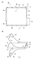
- FIG. 1A is a diagram illustrating an example of a packaged electrode
- FIG. 1B is a perspective view schematically illustrating a state in which electrodes and a pair of separators are sequentially stacked from the front end side in the transport direction.
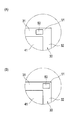
- 2A and 2B are enlarged views of the portion 2 surrounded by the two-dot chain line in FIG. 1, and are explanatory diagrams for explaining the position of the “front end” where a pair of separators are joined together. is there.
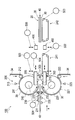
- FIG. 3 is a block diagram showing a main part of the device for manufacturing a packaged electrode.
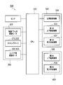
- FIG. 4 is a block diagram showing a control system of the device for manufacturing a packaged electrode.
- 5A is a plan view showing the first joint portion, FIG.
- FIG. 5B is a cross-sectional view taken along line 5B-5B in FIG. 5A
- FIG. 5C is FIG.
- FIG. 5C is a cross-sectional view taken along line 5C-5C, and shows a state during the first joining operation for joining the front ends of the side edges of the separator.
- 6A is a plan view showing the second bonding portion
- FIG. 6B is a cross-sectional view taken along line 6B-6B in FIG. 6A.
- FIG. 7 is a diagram illustrating a state during the second and subsequent joining operations in which the side edges of the separator are joined by the first joining portion.
- FIG. 8 is an enlarged cross-sectional view showing the shape of the pressing portion in the first joint portion.
- FIG. 9A is a diagram showing a state before the joining head moves closer to the workpiece
- FIG. 9B is a state where the joining head moves closer to the workpiece and the pressing portion is in contact with the workpiece.
- FIG. 10A is a view showing a state in which the pressing portion contacts the work and moves backward from the advance position to the retreat position, and the tip of the joining tip comes into contact with the work
- FIG. 10B shows the state shown in FIG.
- FIGS. 11A to 11H are diagrams schematically showing the reciprocating operation of the pressing portion in the first joint portion.
- FIG. 12A to 12G are diagrams schematically showing the first joining operation in the first joining portion.
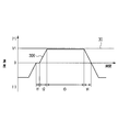
- FIG. 13 is a diagram schematically illustrating changes in the conveyance speed of the workpiece conveyed by the cylindrical rotating body and the speed of the first joint that reciprocates a plurality of times.
- FIG. 1 (A), (B), and FIG. 3 indicate the conveyance direction in which the electrode 40 and the pair of separators 30 are conveyed when the packaged electrode 20 is manufactured.
- the right side in the drawing is the downstream side in the transport direction and is referred to as “front” in each member, and the left side in the drawing is the upstream side in the transport direction.
- the edge of the separator positioned in the direction intersecting the transport direction is referred to as “side edge”
- the edge of the separator positioned in the transport direction is referred to as “front edge” and “rear edge”.
- a laminated body in which the electrode 40 is sandwiched between a pair of separators 30 and before the joining of the separators 30 is completed is also referred to as “work W”.
- the packaged electrode 20 has a positive electrode 40 or a negative electrode 40 packaged in a bag shape with a pair of separators 30.
- the positive electrode is the packaged electrode 20.
- the electrode 40 includes a main body 41 in which an active material is applied to both surfaces of a metal foil, and a tab 42 that is formed from a part of the metal foil and is electrically connected to other members.
- the separator 30 is a thin film made of a resin material, and has a size slightly larger than the main body 41 of the electrode 40. Only the main body 41 of the electrode 40 is sandwiched between the pair of separators 30 so that the tab 42 of the electrode 40 faces the outside. Side edges 31 of the paired separators 30 are joined to each other.
- At least one edge of the front edge 32 or the rear edge 33 of the paired separators 30 is joined.
- the rear edges 33 of a pair of stacked separators 30 are joined.
- the junction point 50 at the side edge 31 is, for example, 5 points, and the junction point 50 at the rear edge 33 is, for example, 4 points.
- the “front end 51” that joins the separators 30 can be set freely from the viewpoint of suppressing so-called opening of the stacked separators 30. For example, a position aligned with the main body 41 of the electrode 40 (FIG. 2 (A )) Or the corners of the separator 30 (FIG. 2 (B)), as well as the literal positions of the active material application line.
- the manufacturing apparatus 100 of the packaged electrode 20 is briefly described as a transport unit 200 that sequentially stacks the electrode 40 and the pair of separators 30 from the front end 51 side in the transport direction, and the pair of separators 30. It has the 1st junction part 300 which joins the side edges 31, and the 2nd junction part 400 which joins at least one edge of the front edge 32 or the back edge 33 of a pair of separator 30. . Then, the side edges 31 of the pair of separators 30 that are sequentially overlapped while being transported by the transport unit 200 are sequentially joined by the first joining unit 300 from the front end 51 side in the transport direction, and the transport by the transport unit 200 is stopped.
- At least one edge of the front edge 32 and the rear edge 33 of the pair of separators 30 is joined by the second joint portion 400.
- the second joint portion 400 joins the rear edges 33 of the pair of separators 30 to each other. Details will be described below.
- the conveyance unit 200 includes a pair of cylindrical drums 210 and 220 that hold a pair of separators 30, an electrode carry-in unit 230 disposed on the upstream side of the pair of lamination drums 210 and 220, and a pair of And a plurality of downstream-side transport units 241 and 242 disposed on the downstream side of the stacking drums 210 and 220.
- a nip portion 215 for sandwiching the workpiece W is formed between the pair of laminated drums 210 and 220.
- the gap size of the nip portion 215 is appropriately adjusted according to the thickness of the workpiece W.
- the electrode carry-in part 230 feeds the electrode 40 formed in a predetermined shape into the nip part 215 along the tangential direction.
- a plurality of downstream-side transport units 241 and 242 are provided to transport the stacked electrodes 40 and the pair of separators 30.
- two downstream transport sections 241 and 242 are provided, and the second joint section 400 is disposed between the downstream transport sections 241 and 242.
- the electrode carrying-in unit 230 includes, for example, an adsorption device 231 that can adsorb and convey the electrode 40, a support roller 232 that supports the electrode 40 conveyed by the adsorption device 231, and the electrode 40 tangentially to the nip portion 215. And a pair of carry-in rollers 233 for feeding along.
- the adsorbing device 231 descends vertically to adsorb the electrode 40, moves up while maintaining the substantially horizontal state of the electrode 40, and then moves downstream in the transport direction.
- Each of the carry-in rollers 233 is provided so as to be movable toward and away from the electrode 40 conveyed by the suction device 231, and feeds the electrode 40 into the nip portion 215 along the tangential direction by sandwiching and rotating the electrode 40.
- the position of the electrode 40 that is attracted by the suction device 231 may be shifted in the transport direction or may be shifted obliquely with respect to the transport direction.
- a position shift of the electrode 40 to be adsorbed and conveyed is detected in advance by a sensor camera.
- the adsorption device 231 moves after adsorbing the electrode 40 while correcting the posture of the electrode 40 to an appropriate posture. Thereby, the electrode 40 is conveyed to the nip portion 215 in a proper posture state.
- the pair of laminated drums 210 and 220 are arranged in pairs in the vertical direction, and each has a cylindrical shape.
- the pair of laminated drums 210 and 220 are arranged in such a manner that the rotating shafts face each other in parallel with a predetermined gap therebetween while being orthogonal to the transport direction.
- Each of the lamination drums 210 and 220 has a holding surface 211 or 221 that holds the separator 30 on its peripheral surface.
- the stacking drums 210 and 220 convey the separator 30 formed in a predetermined shape while holding it on the peripheral surface.
- the width in the rotation axis direction on the holding surfaces 211 and 221 of the laminated drums 210 and 220 is narrower than the width of the separator 30.
- the transport unit 200 transports each of the pair of separators 30 in a state where the side edges 31 protrude beyond the holding surfaces 211 and 221.
- the means for holding the separator 30 on the holding surfaces 211 and 221 of the lamination drums 210 and 220 is not particularly limited, and suction adsorption or electrostatic adsorption can be applied.
- the holding surfaces 211 and 221 have a plurality of air suction holes. The separator 30 is held on the holding surfaces 211 and 221 by sucking air from these air suction holes.
- the pair of laminated drums 210 and 220 rotate in the same direction toward the front in the conveying direction at the nip portion 215. That is, the upper laminated drum 210 rotates counterclockwise in FIG. 3 to convey the separator 30 attached to the holding surface 211 toward the nip portion 215.
- the lower stacking drum 220 rotates in the clockwise direction to convey the separator 30 attached to the holding surface 221 toward the nip portion 215.
- the pair of laminated drums 210 and 220 are synchronously rotated by a laminated drum drive motor 501 connected to a rotating shaft.
- the control unit 500 controls the rotation of the laminated drum drive motor 501.
- the electrode carry-in unit 230 conveys the electrode 40 in a substantially horizontal state in synchronization with the rotation of the lamination drums 210 and 220 and feeds it into the nip unit 215 along the tangential direction.
- the pair of laminated drums 210 and 220 feeds the separator 30 attached to the holding surfaces 211 and 221 to the nip portion 215 according to the rotation.
- the conveyance part 200 can be laminated
- the separator 30 is formed by cutting out from a continuous separator member 34 that is sequentially fed from a separator roll (not shown).
- Timing rollers 212 and 222 that sandwich the separator member 34 between the stacking drums 210 and 220 are disposed on the pair of stacking drums 210 and 220, respectively.
- the controller 500 controls the operation of the timing rollers 212 and 222 and controls the timing at which the separator member 34 is sent to the stacking drums 210 and 220.
- An upper separator cutter 213 is provided above the upper lamination drum 210, and a lower separator cutter 223 is provided below the lower lamination drum 220.
- the separator member 34 is attached to the holding surfaces 211 and 221 of the stacking drums 210 and 220 and conveyed.
- the separator cutters 213 and 223 By operating the separator cutters 213 and 223 at the timing when the separator member 34 is conveyed to a predetermined position, the separator 30 having a predetermined shape is cut out from the separator member 34.
- the two downstream transport units 241 and 242 are, for example, a first conveyor 241 that places and transports the workpiece W fed from the nip 215 of the stacking drums 210 and 220, and a downstream side of the first conveyor 241. And a second conveyor 242 for placing and transporting the workpiece W on which the joining of the side edges 31 of the separator 30 has been completed.
- a second joint 400 is disposed between the first conveyor 241 and the second conveyor 242. After the rear edges 33 of the pair of separators 30 are joined to each other by the second joining portion 400, the second conveyor 242 transports the manufactured packed electrode 20 toward the stage where the next process is performed.
- the first and second conveyors 241 and 242 can be constituted by suction conveyors, for example.
- the widths of the first and second conveyors 241 and 242 are narrower than the width of the separator 30 so as not to interfere with the reciprocating movement of the first joint 300 described later (FIG. 6A). See).
- the first and second conveyors 241 and 242 are rotationally driven in synchronism with the conveyance of the workpiece W by conveyor drive motors 502 and 503 connected to rollers.
- the control unit 500 controls the rotation of the conveyor drive motors 502 and 503.
- the conveyor is used as the some downstream conveyance parts 241,242, you may use other conveying apparatuses, such as a suction hand.
- a pair of first joining portions 300 are provided on the upper and lower sides facing each other across the conveyance path for conveying the stacked electrode 40 and the pair of separators 30, that is, the conveyance path for the workpiece W (FIG. 5B, See C)).
- a pair of second joining portions 400 are also provided on the upper and lower sides facing each other across the conveyance path of the workpiece W. (See FIG. 6B). Since it joins from each of both surfaces of the separator 30 which makes a pair, compared with the case where it joins from only one side, a uniform joining state can be created. Further, when applying the separator 30 having a different material, in particular, a thermal property, adjustment for optimizing the joining conditions is facilitated.
- first and second joint portions 300 and 400 means for joining edges of the pair of separators 30 that are overlapped is not particularly limited, and any means of heat welding, pressure bonding, adhesion, or welding is applied. be able to. In this embodiment, joining is performed by heat welding. This is because the resin separators 30 can be easily joined together.
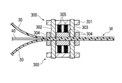
- the first joining portion 300 has a joining head 301 that can move relative to and away from the workpiece W. Bonding chips 302 and 303 for bonding the separators 30 to each other and a pressing portion 304 for pressing the workpiece W are attached to the bonding head 301.
- the pressing portion 304 is capable of moving forward and backward between a forward position (FIG. 9A) beyond the tips of the joint tips 302 and 303 and a backward position (FIG. 10A) retreating from the forward position. Is attached.
- a clamp spring 305 is provided as a biasing member that biases the pressing portion 304 with a biasing force that moves the pressing portion 304 toward the forward movement position.
- the pressing portion 304 contacts the workpiece W and moves backward from the forward movement position to the backward movement position.
- the tips of the chips 302 and 303 come into contact with and join the workpiece W (see FIGS. 9A, 9B, and 10A).
- the joining head 301 moves away from the workpiece W from the state where the tips of the joining chips 302 and 303 are in contact with the workpiece W, so that the pressing portion 304 keeps pressing the workpiece W.
- the tips of the chips 302 and 303 are separated from the workpiece W (FIGS. 10A and 10B).
- the presser 304 is moved forward from the retracted position to the advanced position by the urging force of the clamp spring 305 and separated from the workpiece W.
- the first joint portion 300 has a rear position on the rear side in the conveyance direction of the workpiece W (a position indicated by reference numeral P1 in FIG. 11A) and a front position on the front side in the conveyance direction of the workpiece W (FIG. 11 ( C) is moved back and forth between the position indicated by the symbol P2. Further, the first joint portion 300 includes a gripping position (a position indicated by reference numeral P3 in FIG. 12B) for gripping the workpiece W by the pressing portion 304 and a release position for releasing the gripping of the workpiece W by the pressing portion 304. It moves up and down between (the position indicated by symbol P4 in FIG. 12A).
- the first joint portion 300 is reciprocally driven between the rear position P1 and the front position P2 by a reciprocating drive mechanism 504 including a ball screw, a motor, and the like.
- the first joint 300 is driven up and down between a gripping position and a release position by a first vertical driving mechanism 505 including a ball screw, a motor, and the like.
- the controller 500 performs operation control of the reciprocating drive mechanism 504 and the first vertical drive mechanism 505, respectively.
- the bonding chips 302 and 303 generate heat when power is supplied from the first power supply device 507 (FIG. 4).
- the control unit 500 controls the first power supply device and adjusts the energization amount and energization time to the bonding chips 302 and 303 to adjust the temperature of the bonding chips 302 and 303.
- the first joining portion 300 is a first joining tip 302 that joins the side edges 31 of the pair of separators 30, and the pair of separators 30 that are located downstream of the first joining tips 302 in the transport direction. And at least one (1 in the illustrated example) second joining chip 303 that joins the side edges 31 of each other.
- the side edges 31 of the separator 30 are joined to each other at the two joining chips 302 and 303.
- the separator 30 after being joined forms a plurality (five points in the illustrated example) of joining points 50 along the side edge 31.
- the front ends 51 at the side edges 31 of the pair of separators 30 that are sequentially overlapped while being transported by the transport unit 200 are upstream before being transported to the second joining chip 303 on the downstream side. It is joined by the first joining chip 302 on the side (FIG. 5C).
- the second joining chip 303 on the downstream side performs an idle driving operation.
- the side edges 31 of the pair of separators 30 transported by the transport unit 200 are connected to the first joining chip 302 and It is joined by both of the second joining chips 303 (FIG. 7). A total of three bonding operations are repeated to form five bonding points 50.
- the pressing portion 304 functions as a clamp member that moves together with the joint portion while sandwiching the pair of separators 30 therebetween.
- the pair of separators 30 can be transported by moving the joining portion with the pair of separators 30 sandwiched between the pressing portions 304 that function as clamp members.
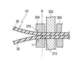
- the pressing portion 304 has a tapered portion 310 that widens toward the upstream side in the transport direction of the separator 30 (FIG. 8). This is because it can be prevented that the transported electrode 40 and the tip of the separator 30 collide with the pressing portion 304 to cause a transport failure.
- the radius of curvature r1 of the tapered portion 310 of the pressing portion 304 is smaller than the radius of curvature R1 of the circumferential surfaces of the laminated drums 210 and 220, and the curvature of the tapered portion 310 is larger than the curvature of the circumferential surfaces of the laminated drums 210 and 220.
- symbol O in FIG. 8 has shown the straight line which connects the center of a pair of lamination
- the pressing portion 304 has a heat radiating means 320. This is to prevent the active material and the like in the electrode 40 from being adversely affected by the heat accumulated in the pressing portion 304 accompanying the bonding.
- the heat dissipating means 320 (FIG. 5C) is configured by using, for example, a material having good thermal conductivity as a material for forming the pressing portion 304, or by heat radiating fins 321 connected to the pressing portion 304 as illustrated. Can be. By simply forming the holding portion 304 from a material having a good thermal conductivity, such as aluminum, the heat dissipation efficiency of the holding portion 304 can be easily increased. By using the heat radiating fins 321 as the heat radiating means 320, the efficiency of heat radiation of the pressing portion 304 can be further enhanced.
- a space 322 for heat release is formed around the heat dissipating means 320 in the pressing portion 304. This is because the efficiency of heat dissipation of the eaves pressing portion 304 can be increased by causing the air flow to be generated by the movement of the first joint portion 300 and diffusing the heat radiated from the heat radiating means 320.
- the pressing portion 304 is preferably formed from a wall member 324 that is disposed so as to surround each of the first and second bonding tips 302 and 303 and includes an opening 323 that faces the bonding chips 302 and 303 outward ( (See FIG. 5A). This is because by arranging the wall member 324 in a U-shape, heat can be easily released while maintaining the original function of the pressing portion 304 for pressing the separator 30, and the heat dissipation of the pressing portion 304 can be secured.
- the second joint portion 400 similar to the first joint portion 300, includes a joining head 401, a joining tip 402, a pressing portion 404, a clamp spring 405 as an urging member, have.
- the second bonding portion 400 also moves the bonding head 401 relatively close to the workpiece W, so that the pressing portion 404 contacts the workpiece W and moves backward from the forward movement position to the backward movement position.
- the tip contacts the workpiece W.
- the bonding head 401 moves away from the workpiece W from the state in which the tip of the bonding tip 402 is in contact with the workpiece W, the bonding tip 402 remains pressed by the pressing portion 404.
- the front end of the holding member 404 moves away from the workpiece W, and the pressing portion 404 moves forward from the retracted position to the advanced position by the urging force of the urging member 405 and moves away from the workpiece W.
- the second joint 400 does not reciprocate in the conveyance direction of the workpiece W, and is between a gripping position where the workpiece W is gripped by the pressing portion 404 and a release position where the gripping of the workpiece W by the pressing portion 304 is released. It only moves up and down.
- the second joint 400 is driven up and down between a gripping position and a release position by a second vertical drive mechanism 506 provided with a ball screw, a motor, or the like.
- the control unit 500 controls the operation of the second vertical drive mechanism 506. Further, the bonding chip 402 generates heat when power is supplied from the second power supply device 508 (see FIG. 4).
- the control unit 500 controls the second power supply device, adjusts the energization amount and energization time to the bonding chip 402, and adjusts the temperature of the bonding chip 402.
- the second bonding portion 400 includes a plurality (four in the illustrated example) of bonding chips 402. In these four joining chips 402, the rear edges 33 of the separator 30 are joined together. As shown in FIG. 1A, the separator 30 after being joined forms a plurality (four in the illustrated example) of joining points 50 along the rear edge 33.
- the manufacturing apparatus 100 for the packaged electrode 20 includes a control unit 500 that controls each unit.
- the control unit 500 is mainly configured by a CPU 510, a memory storing a control program, an operation panel, and the like.
- the CPU 510 receives signals from various sensors that detect the transport position and orientation of the separator 30 and the electrode 40. From the CPU 51, signals for controlling these operations are output to the laminated drum drive motor 501, the timing rollers 212 and 222, and the conveyor drive motors 502 and 503 in the transport unit 200. From the CPU, a signal for controlling these operations is output to the reciprocating drive mechanism 504, the first vertical drive mechanism 505, and the first power supply device 507 in the first joint portion 300. Further, the CPU outputs a signal for controlling these operations to the second vertical drive mechanism 506 and the second power supply device 508 in the second joint portion 400.
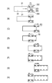
- FIG. 11A to 11H schematically show the reciprocating motion of the pressing portion 304 in the first joint portion 300.
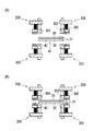
- FIGS. 12A to 12G schematically show the first joining operation in the first joining portion 300.
- the first joint 300 reciprocates between the rear position P1 and the front position P2 (FIGS. 11A to 11C), and moves up and down between the gripping position P3 and the release position P4 (FIG. 11). 12 (A), (B)).
- the solid line arrow indicates the forward movement of the first joint part 300
- the broken line arrow indicates the backward movement of the first joint part 300.
- the first joining unit 300 moves forward in synchronization with the movement of the separator 30 by the transport unit 200.
- FIGS. 11B to 11H the first joint portion 300 is shown as gripping and transporting the separator 30.
- FIG. 12 shows a state in which the first joint 300 is moving forward in synchronization with the transport of the separator 30.
- the electrode 40 and the pair of separators 30 are conveyed by the conveying unit 200, they are sequentially stacked from the front end 51 side in the conveying direction. At this time, the electrode 40 is transported forward in a substantially horizontal state in synchronization with the rotation of the stacking drums 210 and 220 by the electrode carry-in unit 230 in the transporting unit 200, and is tangential to the nip portion 215 of the stacking drum 210 and the rod 220. Feed along.
- the separators 30 cut into a predetermined shape by the stacking drums 210 and 220 in the transport unit 200 are attached to the holding surfaces 211 and 221 of the stacking drums 210 and 220 and transported toward the nip unit 215 according to the rotation.
- the upper and lower first joints 300 are normally open in the vertical direction and are located at the release position P4 (FIG. 12A).
- the first joining portion 300 is closed when the separator 30 is conveyed, and grips the tip end portion of the side edge 31 of the separator 30 (FIG. 11B).
- the first joining portion 300 reaches the gripping position P3 before the separator 30 passes through the first joining tip 302 on the upstream side and reaches the second joining tip 303 on the downstream side. Is gripped (FIG. 12B).
- the first joint portion 300 moves forward to the front position P2 while synchronizing the rotation of the lamination drums 210 and 220 while holding the separator 30 (FIG. 11C). While the first joining portion 300 moves from the rear position P1 to the front position P2, the side edges 31 of the pair of separators 30 are joined by the upstream first joining tip 302 (FIG. 12C, ( D)).
- the second joining chip 303 on the downstream side performs an idle driving operation (FIGS. 12C and 12D).
- the upper and lower first joining portions 300 are opened and returned to the release position P4 to release the grip of the separator 30 (FIGS. 12E and 12F).
- the 1st junction part 300 moves back to back position P1 (Drawing 11 (D) and Drawing 12 (G)).
- the first joining portion 300 closes again and reaches the gripping position P3, grips the side edge 31 of the separator 30, and moves forward to the front position P2 in synchronization with the rotation of the stacking drums 210 and 220 (FIG. 11). (E)). While the 1st junction part 300 moves from back position P1 to front position P2, side edges 31 of a pair of separators 30 are joined by both the 1st joining tip 302 and the 2nd joining chip 303.
- the upper and lower first joining parts 300 are opened and returned to the release position P4 to release the grip of the separator 30.
- the 1st junction part 300 moves back to back position P1 (Drawing 11 (F)).
- the first joining portion 300 closes again and reaches the gripping position P3, grips the side edge 31 of the separator 30, and moves forward to the front position P2 in synchronization with the rotation of the stacking drums 210 and 220 (FIG. 11). (G)). While the 1st junction part 300 moves from back position P1 to front position P2, side edges 31 of a pair of separators 30 are joined by both the 1st joining tip 302 and the 2nd joining chip 303.
- the upper and lower first joining parts 300 are opened and returned to the release position P4 to release the grip of the separator 30.
- the 1st junction part 300 moves back to back position P1 (Drawing 11 (H)).
- the first joint portion 300 repeats the joint operation three times in total to form five joint points 50.
- the first joining portion 300 joins the side edge 31 of the separator 30 a plurality of times from the front end 51 side in the transport direction, so that the side edge 31 of the separator 30 can be joined over a wide range.
- the work W sent out from the nip portion 215 of the stacking drums 210 and 220 is placed on the first conveyor 241 and conveyed.
- the front of the workpiece W is placed on the second conveyor 242.
- the workpiece W is conveyed by the second conveyor 242 and the rear edges 33 of the pair of separators 30 reach the position of the bonding chip 402 of the second bonding portion 400, the conveyance of the workpiece W by the second conveyor 242 is temporarily stopped. To do.
- the second joining portion 400 In a state where the conveyance of the pair of separators 30 is stopped, the second joining portion 400 is closed and reaches the gripping position, and grips the rear edge 33 of the separator 30. While the conveyance of the pair of separators 30 is stopped, the rear edges 33 of the pair of separators 30 are joined together by the four joining tips 402.
- the second bonding portion 400 performs a bonding operation only once, and simultaneously forms four bonding points 50 in the illustrated example.
- the upper and lower second joining portions 400 are opened and returned to the release position, and the gripping of the separator 30 is released. Thereby, the joining of the separators 30 to the workpiece W is completed, and the packaged electrode 20 in which the side edges 31 and the rear end edges of the pair of separators 30 are joined is manufactured.
- the second conveyor 242 is driven again, and conveys the manufactured packaged electrode 20 toward the stage where the next process is performed.
- the positive electrode packing electrode 20 and the negative electrode electrode 40 of the counter electrode and the positive electrode packing electrode 20 are alternately stacked to manufacture a battery cell.
- FIG. 13 schematically shows changes in the conveyance speed of the workpiece W conveyed by the lamination drums 210 and 220 and the speed of the first joint 300 that reciprocates a plurality of times.
- the speed is positive when moving forward in the transport direction.
- the workpiece W passing through the nip portion 215 is conveyed at a speed V1 by the rotation of the stacking drums 210 and 220.
- the first joint 300 is reciprocated between the rear position P1 and the front position P2 by the reciprocating drive mechanism 504.
- the time t1 in the figure indicates the time during which the first joint portion 300 is waiting at the rear position P1 in order to take the timing of the transfer of the workpiece W
- the time t2 is the time when the first joint portion 300 moves forward. It shows the time of acceleration for the first time.
- Time t3 indicates the time during which the first joint 300 is moved so that the relative speed difference with the conveyance speed of the workpiece W approaches zero
- time t4 indicates that the first joint 300 moves backward. Shows the time you are slowing down.
- the first joining portion 300 joins the side edges 31 of the stacked separators 30 while moving together with the workpiece W. Moreover, the 1st junction part 300 has performed joining several times (this embodiment 3 times) from the front end 51 side of a conveyance direction, moving while moving. If the workpiece W and the first joint portion 300 are not moved at substantially the same speed, the workpiece W is wrinkled or poorly joined.
- the first joint 300 that joins the side edges 31 of the pair of separators 30 is moved so that the relative speed difference from the conveyance speed of the workpiece W approaches zero.
- the joining to be performed is repeated a plurality of times from the front end 51 side in the transport direction. Since the separator 30 is sequentially welded a plurality of times from the front end 51 side while transporting the separator 30, the process time can be shortened while preventing the separator 30 from opening. In addition, good bonding can be performed without causing wrinkles in the workpiece W.
- the moving speed of the first bonding portion 300 becomes constant. It is difficult to align the acceleration of the separator 30 and the first joint 300 itself, and it is easier to adjust the joining timing than when joining the separator 30 and the first joint 300 while accelerating them. Because it becomes.
- the side edges 31 of the pair of separators 30 that are sequentially overlapped while being conveyed are sequentially joined by the first joining portion 300.
- the so-called opening of the pair of separators 30 can be prevented, and when the pair of separators 30 are stacked on the electrode 40, the separators 30 are not turned or wrinkled.
- work which joins the edges 31 becomes easy.
- the pair of separators 30 move together with the first joint portion 300 while being sandwiched between the pressing portions 304 as clamp members. Since it can join, fixing the position of the separator 30 with the holding
- the transport unit 200, the first joint unit 300, and the second joint unit 400 have the above-described configuration
- the control unit 500 further includes the transport unit 200 and the first joint unit 300.
- joining is performed a plurality of times from the front end 51 side in the transport direction while moving the joint portion that joins the side edges 31 of the pair of separators 30 so that the relative speed difference from the transport speed of the workpiece W approaches zero. Repeatedly.
- the process time can be shortened while preventing the separator 30 from opening.
- good bonding can be performed without causing wrinkles in the separator 30.
- Joining is performed when the moving speed of the first joint 300 becomes constant. It is difficult to align the acceleration of the separator 30 and the first joint 300 itself. For this reason, compared with the case where it joins while accelerating both the separator 30 and the 1st junction part 300, adjustment of the timing of joining etc. becomes easy, As a result, it can join accurately.
- the side edges 31 of the pair of separators 30 that are sequentially overlapped while being transported are sequentially joined by the first joint portion 300 from the front end 51 side in the transport direction. According to this, the opening of the pair of separators 30 can be prevented, and when the pair of separators 30 is stacked on the electrode 40, the separators 30 are not turned up or wrinkled, and the pair of separators 30 side
- the pair of separators 30 are moved together with the first joint portion 300 while being sandwiched between pressing portions 304 as clamp members. According to this, since it can join, fixing the position of the separator 30 with the holding
- this embodiment has the following features.
- the electrodes 40 and the pair of separators 30 are sequentially stacked from the front end 51 side in the transport direction, and the side edges 31 of the pair of separators 30 are sequentially joined from the front end 51 side in the transport direction.
- the rear edges 33 of the pair of separators 30 are joined together in a state where the conveyance of the pair of separators 30 is stopped.
- the side edges 31 of the pair of separators 30 that are sequentially overlapped while being transported are sequentially joined by the first joining portion 300 from the front end 51 side in the transport direction, so-called opening of the pair of separators 30 is performed. Can be prevented.
- the separators 30 are stacked on the electrode 40, the separators 30 are not turned or wrinkled, and the joining operation for joining the side edges 31 of the pair of separators 30 becomes easy.
- the separators 30 are joined not only on the two sides facing each other in a plan view but also on the other sides. Become.
- the separators 30 are not turned or wrinkled, and the troublesome work of correcting the turning or wrinkles does not occur. In this way, when the pair of separators 30 are stacked on the electrode 40 or after that, the separator 30 is prevented from being turned or wrinkled, thereby improving the production efficiency of the packaged electrode 20, and the battery. It becomes possible to contribute to the efficiency improvement of the whole manufacture.
- the packaged electrode 20 has a configuration in which the electrode 40 is sandwiched between a pair of separators 30, and the electrode 40 and the pair of separators 30 must be transported synchronously and transported for timing. And the conveyance stop is repeated. By using the conveyance stop time for taking such a timing, the rear edges 33 of the pair of separators 30 are joined in a state where the conveyance by the conveyance unit 200 is stopped within the defined conveyance tact limit. Can do. Therefore, it is possible to join the rear edge 33 of the separator 30 in addition to the side edge 31 of the separator 30 without reducing the speed of packing the electrode 40 into the pair of separators 30.
- the second joint 400 is disposed between the downstream transport units 241 and 242 (between the first conveyor 241 and the second conveyor 242), and the electrode 40 and the pair of separators 30 after being stacked are disposed.
- the rear edges 33 of the separators 30 are joined to each other in the course of the transport path. According to this, the rear edge 33 of the separator 30, which is a portion overlapping the stacking drums 210 and 220, can be joined without reducing the speed at which the electrodes 40 are packed in the pair of separators 30.
- Each of the pair of separators 30 is conveyed in a state where each of the side edges 31 protrudes beyond the holding surface 211 and the flange 221.
- the first joining portion 300 interferes with the stacking drum 210 and the flange 220 at a portion where the pair of separators 30 are separated from the holding surfaces 211 and 221 of the stacking drums 210 and 220, that is, at a side portion of the nip portion 215. It can arrange without.
- a joining operation for sequentially joining the side edges 31 of the pair of separators 30 from the front end 51 side in the transport direction can be performed.
- the front end 51 in the transport direction in which the pair of separators 30 are superposed is joined as soon as they are separated from the stacking drums 210 and 220.
- the rear end sides of the pair of separators 30 are conveyed while being sandwiched between the stacking drums 210 and 220.
- Each of the pair of separators 30 is held on the surface of each of a pair of cylindrical rotating bodies, that is, the stacking drums 210 and 220, and is conveyed toward the electrode 40. According to this, since the pair of separators 30 is conveyed while being held on the arc surface, it is possible to easily overlap the side edges 31 sequentially while conveying the pair of separators 30.
- the front ends 51 at the side edges 31 of the pair of separators 30 are overlapped sequentially from the front end 51 side in the transport direction while transporting the electrode 40 and the pair of separators 30, and the transport direction of the two joining chips 302 and 303.
- the first joining chip 302 on the upstream side is joined.
- the front ends 51 at the side edges 31 of the pair of separators 30 that are sequentially overlapped while being transported are joined by the first joining chip 302 on the upstream side of the first joining part 300, and thus the pair of separators 30. So-called mouth opening can be prevented.
- the separators 30 are stacked on the electrode 40, the separators 30 are not turned or wrinkled, and the joining operation for joining the side edges 31 of the pair of separators 30 becomes easy. In this way, when the pair of separators 30 are stacked on the electrode 40, the separator 30 is prevented from being turned or wrinkled, and the production of the packaged electrode 20 is made efficient. It becomes possible to contribute to efficiency improvement.
- the side edges 31 of the pair of separators 30 to be conveyed are joined together by a plurality of joining chips 302 and 303. According to this, since the side edges 31 of the pair of separators 30 are bonded to each other by the plurality of bonding chips 302 and 303, the bonding time can be shortened, and the manufacturing speed can be increased.
- a joining head 301 including joining chips 302 and 303 for joining a pair of separators 30 and a pressing part 304 that presses the work W is moved relatively close to the work W, and the work W is moved by the pressing part 304. After pressing, the pair of separators 30 are joined together by the joining tips 302 and 303. Then, after the joining head 301 is moved away from the workpiece W and the joining tips 302 and 303 are separated from the pair of separators 30, the clamping of the workpiece W by the pressing portion 304 is released.
- the pressing of the workpiece W by the pressing portion 304 and the bonding by the bonding tips 302 and 303 are performed by one action of moving the bonding head 301 relatively close to the workpiece W within one process. Since this can be done, the cycle time can be reduced. In this way, the cycle time required to pack the electrode 40 between the pair of separators 30 is shortened, and the manufacturing efficiency of the packed electrode 20 is improved, thereby contributing to the efficiency of manufacturing the entire battery. It becomes possible to do. Further, since the bonding by the bonding tips 302 and 303 is performed after the pressing portion 304 presses the work W, the bonding can be performed with high accuracy.
- the pressing portion 304 holds the work W until the joining chips 302 and 303 are separated from the work W. For this reason, when the front-end
- the pair of laminated drums 210 and 220 are arranged up and down, they may be arranged in other directions.
- the electrode 40 is conveyed along a tangential direction between the lamination drums 210 and 220 (a direction orthogonal to a straight line connecting the centers of the pair of lamination drums 210 and 220).
- the electrode 40 may be conveyed in the vertical direction from above or below.
- one continuous separator member 34 is attached to the peripheral surfaces of the stacking drums 210 and 220 by the separator cutters 213 and 223, the separator 30 is cut into a predetermined shape. You may affix on 210 and 220, and may convey.
- the cycle time required to pack an electrode between a pair of separators can be shortened, and the production efficiency of the packed electrode can be improved.
Landscapes
- Engineering & Computer Science (AREA)
- Mechanical Engineering (AREA)
- Chemical Kinetics & Catalysis (AREA)
- Chemical & Material Sciences (AREA)
- Electrochemistry (AREA)
- General Chemical & Material Sciences (AREA)
- Manufacturing & Machinery (AREA)
- Physics & Mathematics (AREA)
- Thermal Sciences (AREA)
- Secondary Cells (AREA)
- Cell Separators (AREA)
- Battery Electrode And Active Subsutance (AREA)
- Sealing Battery Cases Or Jackets (AREA)
Abstract
Priority Applications (7)
| Application Number | Priority Date | Filing Date | Title |
|---|---|---|---|
| MX2013011083A MX2013011083A (es) | 2011-04-07 | 2012-04-06 | Dispositivo para la produccion de electrodo empaquetado y metodo para la produccion de electrodo empaquetado. |
| US14/007,865 US9543560B2 (en) | 2011-04-07 | 2012-04-06 | Device for producing packaged electrode and method of producing packaged electrode |
| CN201280015494.XA CN103460482B (zh) | 2011-04-07 | 2012-04-06 | 装袋电极的制造装置及装袋电极的制造方法 |
| BR112013025404A BR112013025404A2 (pt) | 2011-04-07 | 2012-04-06 | dispositivo e método para produzir um eletrodo embalado |
| RU2013149402/07A RU2551843C1 (ru) | 2011-04-07 | 2012-04-06 | Установка для производства пакетированного электрода и способ производства пакетированного электрода |
| KR1020137028572A KR101564822B1 (ko) | 2011-04-07 | 2012-04-06 | 포장 전극의 제조 장치 및 포장 전극의 제조 방법 |
| EP12768354.8A EP2696427B1 (fr) | 2011-04-07 | 2012-04-06 | Dispositif et procédé de production d'une électrode ensachée |
Applications Claiming Priority (2)
| Application Number | Priority Date | Filing Date | Title |
|---|---|---|---|
| JP2011-085757 | 2011-04-07 | ||
| JP2011085757A JP5684635B2 (ja) | 2011-04-07 | 2011-04-07 | 袋詰電極の製造装置、および袋詰電極の製造方法 |
Publications (1)
| Publication Number | Publication Date |
|---|---|
| WO2012137929A1 true WO2012137929A1 (fr) | 2012-10-11 |
Family
ID=46969317
Family Applications (1)
| Application Number | Title | Priority Date | Filing Date |
|---|---|---|---|
| PCT/JP2012/059543 Ceased WO2012137929A1 (fr) | 2011-04-07 | 2012-04-06 | Dispositif et procédé de production d'une électrode ensachée |
Country Status (11)
| Country | Link |
|---|---|
| US (1) | US9543560B2 (fr) |
| EP (1) | EP2696427B1 (fr) |
| JP (1) | JP5684635B2 (fr) |
| KR (1) | KR101564822B1 (fr) |
| CN (1) | CN103460482B (fr) |
| BR (1) | BR112013025404A2 (fr) |
| MX (1) | MX2013011083A (fr) |
| PT (1) | PT2696427T (fr) |
| RU (1) | RU2551843C1 (fr) |
| TW (1) | TWI432606B (fr) |
| WO (1) | WO2012137929A1 (fr) |
Families Citing this family (14)
| Publication number | Priority date | Publication date | Assignee | Title |
|---|---|---|---|---|
| JP5883694B2 (ja) * | 2011-04-07 | 2016-03-15 | 日産自動車株式会社 | 袋詰電極の製造装置、および袋詰電極の製造方法 |
| JP5820138B2 (ja) | 2011-04-07 | 2015-11-24 | 株式会社京都製作所 | 袋詰電極の製造装置、および袋詰電極の製造方法 |
| JP6022784B2 (ja) | 2011-04-07 | 2016-11-09 | 日産自動車株式会社 | セパレータ溶着装置、およびセパレータの溶着方法 |
| WO2014080544A1 (fr) * | 2012-11-21 | 2014-05-30 | 長野オートメーション株式会社 | Dispositif qui intercale des feuilles d'électrodes avec des séparateurs |
| JP6343898B2 (ja) * | 2013-10-03 | 2018-06-20 | 日産自動車株式会社 | 電気デバイスのセパレータ接合方法および電気デバイスのセパレータ接合装置 |
| US10528946B2 (en) | 2013-11-06 | 2020-01-07 | Tencent Technology (Shenzhen) Company Limited | System and method for authenticating, associating and storing secure information |
| JP6575940B2 (ja) * | 2014-11-14 | 2019-09-18 | 株式会社エンビジョンAescジャパン | 袋詰電極の製造装置、および袋詰電極の製造方法 |
| JP6528457B2 (ja) * | 2015-02-27 | 2019-06-12 | 株式会社豊田自動織機 | セパレータ付き電極の製造装置、及び、セパレータ付き電極の製造方法 |
| JP6511923B2 (ja) * | 2015-04-03 | 2019-05-15 | 株式会社豊田自動織機 | ワーク積層装置 |
| CN109351645A (zh) * | 2018-10-08 | 2019-02-19 | 广州德泰克自动化科技有限公司 | 一种智能自动包裹分拣设备 |
| KR102751961B1 (ko) * | 2018-11-20 | 2025-01-10 | 주식회사 엘지에너지솔루션 | 전극 조립체 제조장치 및 전극 조립체 제조방법 |
| DE102019207402A1 (de) * | 2019-05-21 | 2020-11-26 | Continental Reifen Deutschland Gmbh | Verfahren und Vorrichtung zur Herstellung eines Gummibauteiles |
| CN112310458A (zh) * | 2019-07-31 | 2021-02-02 | 广东利元亨智能装备股份有限公司 | 叠片机 |
| HUE068090T2 (hu) * | 2021-09-17 | 2024-12-28 | Univ Berlin Tech | Eljárás és készülék elektródaelválasztó egység létrehozására akkumulátorcellához |
Citations (5)
| Publication number | Priority date | Publication date | Assignee | Title |
|---|---|---|---|---|
| JP2007250319A (ja) * | 2006-03-15 | 2007-09-27 | Nec Tokin Corp | 積層型電池 |
| JP2007329112A (ja) | 2006-06-09 | 2007-12-20 | Litcel Kk | リチウムイオン電池並びにその製造方法及び製造装置 |
| JP2007329111A (ja) * | 2006-06-09 | 2007-12-20 | Litcel Kk | リチウムイオン電池並びにその製造方法及び製造装置並びに袋入り電極板の製造方法及び製造装置 |
| JP2009123582A (ja) * | 2007-11-16 | 2009-06-04 | Nec Tokin Corp | 積層型二次電池 |
| WO2012070297A1 (fr) * | 2010-11-25 | 2012-05-31 | 株式会社京都製作所 | Appareil de recouvrement pour plaques polaires |
Family Cites Families (34)
| Publication number | Priority date | Publication date | Assignee | Title |
|---|---|---|---|---|
| US2596933A (en) | 1951-01-31 | 1952-05-13 | Dow Chemical Co | Means for welding plastic films |
| US3321353A (en) | 1963-03-08 | 1967-05-23 | Weldotron Corp | Film sealing and cutting apparatus |
| US3729357A (en) | 1971-06-25 | 1973-04-24 | Gen Heat Sealing Corp | Thermoplastic heat sealing apparatus |
| US3874976A (en) | 1973-02-02 | 1975-04-01 | Computron Inc | Gripper jaw assembly |
| JPS5223632A (en) | 1975-08-19 | 1977-02-22 | Shin Kobe Electric Machinery | Method of producing battery |
| US4026000A (en) | 1976-07-15 | 1977-05-31 | Globe-Union Inc. | Apparatus for producing enveloped battery plates |
| US4300977A (en) | 1978-10-24 | 1981-11-17 | Karl Heinz Stiegler | Machine for welding thermoplastic sheets |
| US4337113A (en) | 1979-10-19 | 1982-06-29 | Searle Clifford Arthur | Apparatus for manufacture of sleeves and/or pockets for separator plates |
| JPS5914261A (ja) | 1982-07-15 | 1984-01-25 | Nippon Muki Kk | 蓄電池用袋状抄紙セパレ−タ−並にその製造法 |
| SU1304684A1 (ru) * | 1985-07-10 | 1997-02-27 | Курский завод "Аккумулятор" | Устройство для поштучной выдачи электродов и сепараторов аккумуляторов |
| JPS6264056A (ja) | 1985-09-17 | 1987-03-20 | Matsushita Electric Ind Co Ltd | 鉛蓄電池の製造法 |
| DE3610551A1 (de) | 1985-11-11 | 1987-05-14 | Kiefel Hochfrequenz Paul | Einrichtung zum herstellen von aus kunststoffolienbahnen gebildeten nutzen |
| KR920000181B1 (ko) | 1988-11-22 | 1992-01-10 | 미쓰이세끼유 가가꾸고오교오 가부시끼 가이샤 | 용착날 및 용착장치 |
| AT392371B (de) * | 1989-05-10 | 1991-03-25 | Elbak Batteriewerke Gmbh | Vorrichtung zum eintaschen und abstapeln von positiven oder negativen platten fuer akkumulatoren |
| SU1697148A1 (ru) * | 1989-06-09 | 1991-12-07 | Предприятие П/Я Ю-9474 | Устройство дл набора пакетов электродов аккумул тора |
| JPH0359948A (ja) | 1989-07-27 | 1991-03-14 | Yuasa Battery Co Ltd | 袋状セパレータの製造方法 |
| US5266150A (en) | 1991-03-08 | 1993-11-30 | Rembrandt Photo Services | Thermocontact welding method and apparatus, and welded product |
| US5284002A (en) | 1992-02-25 | 1994-02-08 | Simple Packaging Solutions, Inc. | Apparatus and method for making a reclosable storage bag |
| US6086524A (en) | 1992-02-25 | 2000-07-11 | Martin; Andrew Mcg. | Reclosable storage bag and method for making the same |
| WO1993016931A1 (fr) | 1992-02-25 | 1993-09-02 | Simple Packaging Solutions, Inc. | Appareil et procede de fabrication d'un sac de stockage refermable |
| JPH05275073A (ja) | 1992-03-25 | 1993-10-22 | Matsushita Electric Ind Co Ltd | セパレータの供給、袋化装置 |
| JP3511443B2 (ja) | 1996-12-20 | 2004-03-29 | 株式会社リコー | 電池装置 |
| US6009925A (en) | 1998-02-05 | 2000-01-04 | Hall Dielectric Machinery, Inc. | Apparatus for welding thermoplastic materials |
| GB9806778D0 (en) | 1998-03-31 | 1998-05-27 | Elson & Robbins Limited | Apparatus for the production of pocketed coil springs |
| US6665999B1 (en) | 1999-09-07 | 2003-12-23 | Recot, Inc. | Seal jaw modules for reclose bag modification to vertical form, fill, and seal packaging system |
| RU2176425C2 (ru) * | 1999-10-12 | 2001-11-27 | Уральский электрохимический комбинат | Способ изготовления окисноникелевого электрода для щелочного аккумулятора |
| RU2189886C2 (ru) * | 2000-08-24 | 2002-09-27 | Открытое акционерное общество "Источники тока" | Способ изготовления ламелей электродов щелочных источников тока |
| US20030014859A1 (en) * | 2001-07-23 | 2003-01-23 | Kejha Joseph B. | Method of automated hybrid lithium-ion cells production and method of the cell assembly and construction |
| CN101740792B (zh) | 2003-12-02 | 2012-10-17 | 日产自动车株式会社 | 燃料电池的制造 |
| EP1969655B1 (fr) | 2005-12-27 | 2011-11-23 | LG Chem, Ltd. | Element de cadre et son bloc batterie |
| JP5048404B2 (ja) * | 2007-06-29 | 2012-10-17 | 東レエンジニアリング株式会社 | 2次電池の製造方法および製造装置 |
| JP2009289418A (ja) | 2008-05-27 | 2009-12-10 | Nec Tokin Corp | 積層型二次電池の製造方法 |
| JP6022784B2 (ja) | 2011-04-07 | 2016-11-09 | 日産自動車株式会社 | セパレータ溶着装置、およびセパレータの溶着方法 |
| JP5820138B2 (ja) | 2011-04-07 | 2015-11-24 | 株式会社京都製作所 | 袋詰電極の製造装置、および袋詰電極の製造方法 |
-
2011
- 2011-04-07 JP JP2011085757A patent/JP5684635B2/ja active Active
-
2012
- 2012-04-06 EP EP12768354.8A patent/EP2696427B1/fr active Active
- 2012-04-06 US US14/007,865 patent/US9543560B2/en active Active
- 2012-04-06 KR KR1020137028572A patent/KR101564822B1/ko active Active
- 2012-04-06 BR BR112013025404A patent/BR112013025404A2/pt not_active IP Right Cessation
- 2012-04-06 PT PT127683548T patent/PT2696427T/pt unknown
- 2012-04-06 CN CN201280015494.XA patent/CN103460482B/zh active Active
- 2012-04-06 TW TW101112294A patent/TWI432606B/zh active
- 2012-04-06 MX MX2013011083A patent/MX2013011083A/es unknown
- 2012-04-06 RU RU2013149402/07A patent/RU2551843C1/ru not_active IP Right Cessation
- 2012-04-06 WO PCT/JP2012/059543 patent/WO2012137929A1/fr not_active Ceased
Patent Citations (5)
| Publication number | Priority date | Publication date | Assignee | Title |
|---|---|---|---|---|
| JP2007250319A (ja) * | 2006-03-15 | 2007-09-27 | Nec Tokin Corp | 積層型電池 |
| JP2007329112A (ja) | 2006-06-09 | 2007-12-20 | Litcel Kk | リチウムイオン電池並びにその製造方法及び製造装置 |
| JP2007329111A (ja) * | 2006-06-09 | 2007-12-20 | Litcel Kk | リチウムイオン電池並びにその製造方法及び製造装置並びに袋入り電極板の製造方法及び製造装置 |
| JP2009123582A (ja) * | 2007-11-16 | 2009-06-04 | Nec Tokin Corp | 積層型二次電池 |
| WO2012070297A1 (fr) * | 2010-11-25 | 2012-05-31 | 株式会社京都製作所 | Appareil de recouvrement pour plaques polaires |
Non-Patent Citations (1)
| Title |
|---|
| See also references of EP2696427A4 |
Also Published As
| Publication number | Publication date |
|---|---|
| JP5684635B2 (ja) | 2015-03-18 |
| KR101564822B1 (ko) | 2015-10-30 |
| CN103460482B (zh) | 2016-08-31 |
| MX2013011083A (es) | 2013-12-06 |
| US20140013585A1 (en) | 2014-01-16 |
| EP2696427A1 (fr) | 2014-02-12 |
| BR112013025404A2 (pt) | 2017-11-14 |
| RU2013149402A (ru) | 2015-05-20 |
| CN103460482A (zh) | 2013-12-18 |
| KR20130137233A (ko) | 2013-12-16 |
| TWI432606B (zh) | 2014-04-01 |
| EP2696427A4 (fr) | 2014-08-20 |
| TW201307615A (zh) | 2013-02-16 |
| RU2551843C1 (ru) | 2015-05-27 |
| EP2696427B1 (fr) | 2017-11-15 |
| US9543560B2 (en) | 2017-01-10 |
| PT2696427T (pt) | 2018-02-07 |
| JP2012221711A (ja) | 2012-11-12 |
Similar Documents
| Publication | Publication Date | Title |
|---|---|---|
| JP5684635B2 (ja) | 袋詰電極の製造装置、および袋詰電極の製造方法 | |
| JP5883694B2 (ja) | 袋詰電極の製造装置、および袋詰電極の製造方法 | |
| JP6022784B2 (ja) | セパレータ溶着装置、およびセパレータの溶着方法 | |
| JP5820138B2 (ja) | 袋詰電極の製造装置、および袋詰電極の製造方法 | |
| JP6238506B2 (ja) | 接合装置、および接合方法 |
Legal Events
| Date | Code | Title | Description |
|---|---|---|---|
| 121 | Ep: the epo has been informed by wipo that ep was designated in this application |
Ref document number: 12768354 Country of ref document: EP Kind code of ref document: A1 |
|
| WWE | Wipo information: entry into national phase |
Ref document number: MX/A/2013/011083 Country of ref document: MX |
|
| REEP | Request for entry into the european phase |
Ref document number: 2012768354 Country of ref document: EP |
|
| WWE | Wipo information: entry into national phase |
Ref document number: 2012768354 Country of ref document: EP |
|
| WWE | Wipo information: entry into national phase |
Ref document number: IDW00201304608 Country of ref document: ID |
|
| NENP | Non-entry into the national phase |
Ref country code: DE |
|
| WWE | Wipo information: entry into national phase |
Ref document number: 14007865 Country of ref document: US |
|
| ENP | Entry into the national phase |
Ref document number: 20137028572 Country of ref document: KR Kind code of ref document: A |
|
| ENP | Entry into the national phase |
Ref document number: 2013149402 Country of ref document: RU Kind code of ref document: A |
|
| REG | Reference to national code |
Ref country code: BR Ref legal event code: B01A Ref document number: 112013025404 Country of ref document: BR |
|
| REG | Reference to national code |
Ref country code: BR Ref legal event code: B01E Ref document number: 112013025404 Country of ref document: BR |
|
| ENP | Entry into the national phase |
Ref document number: 112013025404 Country of ref document: BR Kind code of ref document: A2 Effective date: 20131001 |