WO2012137946A1 - 電子機器、操作制御方法および操作制御プログラム - Google Patents
電子機器、操作制御方法および操作制御プログラム Download PDFInfo
- Publication number
- WO2012137946A1 WO2012137946A1 PCT/JP2012/059583 JP2012059583W WO2012137946A1 WO 2012137946 A1 WO2012137946 A1 WO 2012137946A1 JP 2012059583 W JP2012059583 W JP 2012059583W WO 2012137946 A1 WO2012137946 A1 WO 2012137946A1
- Authority
- WO
- WIPO (PCT)
- Prior art keywords
- contact
- state
- unit
- display unit
- detection unit
- Prior art date
- Legal status (The legal status is an assumption and is not a legal conclusion. Google has not performed a legal analysis and makes no representation as to the accuracy of the status listed.)
- Ceased
Links
Images




Classifications
-
- G—PHYSICS
- G06—COMPUTING OR CALCULATING; COUNTING
- G06F—ELECTRIC DIGITAL DATA PROCESSING
- G06F3/00—Input arrangements for transferring data to be processed into a form capable of being handled by the computer; Output arrangements for transferring data from processing unit to output unit, e.g. interface arrangements
- G06F3/01—Input arrangements or combined input and output arrangements for interaction between user and computer
- G06F3/016—Input arrangements with force or tactile feedback as computer generated output to the user
-
- G—PHYSICS
- G06—COMPUTING OR CALCULATING; COUNTING
- G06F—ELECTRIC DIGITAL DATA PROCESSING
- G06F3/00—Input arrangements for transferring data to be processed into a form capable of being handled by the computer; Output arrangements for transferring data from processing unit to output unit, e.g. interface arrangements
- G06F3/01—Input arrangements or combined input and output arrangements for interaction between user and computer
- G06F3/048—Interaction techniques based on graphical user interfaces [GUI]
- G06F3/0487—Interaction techniques based on graphical user interfaces [GUI] using specific features provided by the input device, e.g. functions controlled by the rotation of a mouse with dual sensing arrangements, or of the nature of the input device, e.g. tap gestures based on pressure sensed by a digitiser
- G06F3/0488—Interaction techniques based on graphical user interfaces [GUI] using specific features provided by the input device, e.g. functions controlled by the rotation of a mouse with dual sensing arrangements, or of the nature of the input device, e.g. tap gestures based on pressure sensed by a digitiser using a touch-screen or digitiser, e.g. input of commands through traced gestures
- G06F3/04886—Interaction techniques based on graphical user interfaces [GUI] using specific features provided by the input device, e.g. functions controlled by the rotation of a mouse with dual sensing arrangements, or of the nature of the input device, e.g. tap gestures based on pressure sensed by a digitiser using a touch-screen or digitiser, e.g. input of commands through traced gestures by partitioning the display area of the touch-screen or the surface of the digitising tablet into independently controllable areas, e.g. virtual keyboards or menus
Definitions
- the present invention relates to an electronic device, an operation control method, and an operation control program.
- Patent Document 1 a technique for notifying the user by generating a vibration that an input has been accepted by a contact operation is known (for example, Patent Document 1).
- the user cannot recognize to which position on the touch panel the contact operation is performed only by generating the vibration.
- Various objects such as icons and buttons are usually displayed on the touch panel, and the electronic device changes a function to be executed depending on in which object display area the contact operation is detected. For this reason, it is very important for the user to recognize the position where the contact operation is performed.
- the electronic device does not perform a predetermined process based on an operation by a display unit, a detection unit that detects contact with the display unit, a vibration unit that vibrates the detection unit, and the contact with the display unit.
- a control unit that switches between a first state and a second state in which a predetermined process based on an operation by contact with the display unit is performed, the control unit in the first state on the display unit
- the detection unit is vibrated by the vibration unit based on the contact and is switched from the first state to the second state.
- the operation control method is an operation control method executed by an electronic device including a display unit, a detection unit that detects contact with the display unit, and a vibration unit that vibrates the detection unit.
- the detection unit detects the contact with the display unit, and the detection unit detects the contact with the detection unit.
- the vibration unit vibrates the detection unit, and when the detection unit detects contact with a predetermined position on the display unit, the first unit causes the display unit to Switching to a second state in which a predetermined process based on an operation by contact is performed.
- an operation control program in an electronic device including a display unit, a detection unit that detects contact with the display unit, and a vibration unit that vibrates the detection unit.
- the detection unit detects a contact with the display unit, and the vibration unit vibrates the detection unit based on the contact detected by the detection unit.
- the detection unit detects a contact with a predetermined position on the display unit, a predetermined process based on an operation by the contact with the display unit is performed from the first state. And switching to the second state to be performed.
- the electronic device, the operation control method, and the operation control program according to the present invention have an effect that the user can easily recognize the operation position.
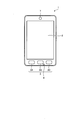
- FIG. 1 is a front view showing an appearance of a mobile phone terminal.
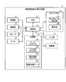
- FIG. 2 is a block diagram showing a functional configuration of the mobile phone terminal.
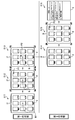
- FIG. 3 is a diagram for explaining a function for causing a user to recognize a contact position.
- FIG. 4 is a diagram illustrating an example of vibration definition data.
- FIG. 5 is a diagram illustrating another example of the vibration definition data.
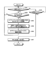
- FIG. 6 is a flowchart showing a processing procedure of contact operation control in the first state.
- FIG. 7 is a flowchart showing a processing procedure of contact operation control in the second state.
- FIG. 8 is a flowchart showing a modification of the processing procedure of the contact operation control in the first state.
- FIG. 9 is a flowchart showing a modification of the processing procedure of the contact operation control in the second state.
- FIG. 10 is a diagram illustrating an example in which a virtual keyboard with a QWERTY layout is displayed on the touch panel.
- FIG. 11 is a diagram illustrating an example in which a ten-key array virtual keyboard is displayed on the touch panel.
- a mobile phone terminal will be described as an example of an electronic device.
- various devices including a touch panel such as PHS (Personal Handyphone System), PDA, etc.
- PHS Personal Handyphone System
- PDA Personal Digital Assistant
- FIG. 1 is a front view showing the appearance of the mobile phone terminal 1.
- the mobile phone terminal 1 has a substantially hexahedron-shaped casing, and includes a touch panel 2, an input unit 3, a speaker 7, and a microphone 8 on the surface of the casing.
- the touch panel 2 is provided on one of the surfaces having the largest area, displays characters, figures, images, and the like, and touches the touch panel 2 using a finger, stylus, pen, or the like (hereinafter simply referred to as “finger”). Detects various operations performed. Note that the touch panel 2 may detect various operations by any method such as a capacitance type, a resistance film type, and a pressure sensitive type.
- the input unit 3 includes a plurality of buttons such as a button 3A, a button 3B, and a button 3C to which a predetermined function is assigned.
- the speaker 7 outputs the other party's voice, music reproduced by various programs, sound effects, and the like.
- the microphone 8 acquires sound at the time of a telephone call or reception of an operation by sound.
- FIG. 2 is a block diagram showing a functional configuration of the mobile phone terminal 1.
- the mobile phone terminal 1 includes a touch panel 2, an input unit 3, a vibration unit 4, a power supply unit 5, a communication unit 6, a speaker 7, a microphone 8, a storage unit 9, and a control.
- the touch panel 2 includes a display unit 2B and a touch sensor 2A (detection unit) superimposed on the display unit 2B.
- the touch sensor 2A detects various operations performed on the touch panel 2 using a finger (operations by contact with the display unit 2B) together with a position on the touch panel 2 where the operation is performed, and the control unit 10 Notify
- the operation detected by the touch sensor 2A includes a tap operation and a swipe operation.
- the tap operation is an operation in which a finger is brought into contact with the touch panel 2 for a short time and then released from the touch panel 2.
- the swipe operation is an operation for moving the finger while keeping the finger in contact with the touch panel 2.
- the display unit 2B includes, for example, a liquid crystal display (LCD, Liquid Crystal Display), an organic EL (Organic Electro-Luminescence) panel, and the like, and displays characters, figures, and the like.
- the input unit 3 receives a user operation through a physical button or the like, and transmits a signal corresponding to the received operation to the control unit 10.
- the vibration unit 4 vibrates at least the touch panel 2 directly or indirectly by generating vibration using a motor, a piezoelectric element, or the like.
- the vibration unit 4 can change the intensity of vibration according to a signal input from the control unit 10.
- changing the vibration intensity may be changing the vibration frequency, changing the vibration amplitude, or changing both the vibration frequency and amplitude. It may be to do.
- the power supply unit 5 supplies power obtained from a storage battery or an external power supply to each functional unit of the mobile phone terminal 1 including the control unit 10.
- the communication unit 6 establishes a radio signal line by a CDMA system or the like with a base station via a channel assigned by the base station, and performs telephone communication and information communication with the base station.
- the speaker 7 outputs the sound signal transmitted from the control unit 10 as sound.
- the microphone 8 converts a user's voice into a voice signal and outputs the voice signal to the control unit 10.
- the storage unit 9 is a storage device such as a nonvolatile memory or a magnetic storage device.
- the storage unit 9 stores programs and data used for processing in the control unit 10.
- Programs stored in the storage unit 9 include a mail program 9A, a browser program 9B, and an operation control program 9C.
- the data stored in the storage unit 9 includes vibration definition data 9D.
- the storage unit 9 also stores other programs and data such as an operating system program and address book data that realize basic functions of the mobile phone terminal 1.
- the mail program 9A provides a function for realizing an electronic mail function.
- the browser program 9B provides a function for realizing a WEB browsing function.
- the operation control program 9 ⁇ / b> C activates various functions according to the input operation detected by the touch panel 2.
- the operation control program 9C provides a function that allows the user to recognize the contact position.
- the vibration definition data 9D holds the definition of the intensity and pattern for vibrating the vibration unit 4 according to the function provided by the operation control program 9C.
- the control unit 10 is, for example, a CPU (Central Processing Unit), and controls the operation of the mobile phone terminal 1 to realize various functions. Specifically, the control unit 10 executes instructions included in the program stored in the storage unit 9 while referring to the data stored in the storage unit 9 and the data expanded in the RAM 11 as necessary. Various functions are realized by controlling the display unit 2B, the communication unit 6, and the like.
- a CPU Central Processing Unit
- the program executed by the control unit 10 and the data to be referred to may be downloaded from the server device by wireless communication by the communication unit 6.
- the program executed by the control unit 10 and the data to be referenced may be stored in a portable storage medium from which information can be read out by a medium reading device (not shown) provided in the mobile phone terminal 1.
- the control unit 10 realizes an electronic mail function by executing the mail program 9A, for example. Moreover, the control part 10 implement
- the RAM 11 is used as a storage area for temporarily storing instructions of a program executed by the control unit 10, data referred to by the control unit 10, calculation results of the control unit 10, and the like.
- FIG. 3 is a diagram for explaining a function for causing a user to recognize a contact position.
- the mobile phone terminal 1 in operation takes either the first state or the second state.
- the first state is a state for allowing the user to recognize the contact position
- the second state is a state for executing various processes (predetermined processes) in accordance with the user's contact operation. .
- the cellular phone terminal 1 is in the first state while the standard screen is displayed on the touch panel 2.
- the standard screen is a screen in a state waiting for various functions such as a call function and an e-mail function.
- the standard screen is a screen before switching to a screen corresponding to various functions provided by the mobile phone terminal 1.
- the standard screen may be called a standby screen, an initial screen, a desktop screen, a home screen, or wallpaper, for example.
- the supply of power to the display unit 2B of the touch panel 2 may be stopped and the display unit 2B may be turned off. However, even when the supply of power to the display unit 2B is stopped, the supply of power to the touch sensor 2A is continued, and the touch sensor 2A is kept in a state where the touch operation can be detected.
- the mobile phone terminal 1 displays a plurality of icons I1 on the standard screen.
- the icons I1 are image objects that are associated with specific functions, and are arranged at equal intervals.
- the icon I1 is used as a clue to make the user recognize the contact position.
- the mobile phone terminal 1 when the mobile phone terminal 1 is in the first state, when the touch operation in the display area of any icon I1 is detected by the touch panel 2, the mobile phone terminal 1 The touch panel 2 is vibrated. The intensity and pattern of the vibration are changed according to the icon I1 in which the contact operation is detected. For this reason, the user can recognize to which icon I1 he / she performed the contact operation based on the intensity or pattern of vibration generated in response to the contact operation.
- the first state since predetermined processing based on an operation by contact is not performed, even if a contact operation on the icon I1 is detected, only a vibration is generated and a function corresponding to the icon I1 is not executed.
- the reference position B1 is set at a predetermined position on the touch panel 2.
- the user knows where the reference position B1 is on the touch panel 2 (for example, the center on the touch panel 2), and remembers in advance the relative position of each object such as the icon I1 viewed from the reference position B1. Yes.
- the mobile phone terminal 1 transitions to the second state when the touch panel 2 detects a position where the reference position B1 is set or a contact operation within the display area of the icon I1 including the reference position B1.
- the user after finding the reference position B1 based on the vibration intensity and pattern, the user performs a contact operation on an arbitrary object based on a known relative position, and activates a function corresponding to the object. be able to.
- the reference position B ⁇ b> 1 is provided near the center of the touch panel 2. Since the vicinity of the center is relatively close to any position on the touch panel 2, it is suitable as a position for setting a clue for performing a contact operation on an arbitrary position on the touch panel 2. Note that the position where the reference position B1 is set may be changed according to the designation of the user or the arrangement of objects such as buttons and icons for receiving input on the screen displayed in the first state.
- step S12 shown in FIG. 3 the user is performing a contact operation at a position P1 on the touch panel 2.
- the position P1 is included in the display area of the icon I1 displayed on the upper right of the touch panel 2. For this reason, when the touch panel 2 detects the touch operation at the position P1, the mobile phone terminal 1 vibrates the vibration unit 4 with the intensity and pattern corresponding to the icon I1 including the position P1.
- the correspondence between the object such as the icon I1 and the intensity and pattern of the vibration is defined in the vibration definition data 9D.
- FIG. 4 is a diagram illustrating an example of the vibration definition data 9D.
- the vibration definition data 9D shown in FIG. 4 has items of display position, intensity, and pattern, and data is registered for each object.
- the display position is a position where the object is displayed.
- the strength is the strength of vibration corresponding to the object, and the larger the value, the stronger the strength.
- the pattern is a vibration pattern corresponding to the object, and a combination of a black circle indicating that vibration is generated for a certain period and a white circle indicating that generation of vibration for a certain period is suppressed is set.
- the vibration definition data 9D shown in FIG. 4 at least one of the intensity and the pattern is different for each object. In this way, by setting the vibration definition data 9D, the user can identify the object that is the target of the contact operation based on the vibration intensity and pattern.
- the vibration definition data 9D may be set in advance or may be set individually by the user.
- FIG. 5 is a diagram showing another example of the vibration definition data 9D.
- the vibration definition data 9D shown in FIG. 5 has items of distance, intensity, and pattern from the reference position, and data is registered for each distance from the reference position.
- the distance from the reference position is a value indicating the distance of the object from the reference position B1.
- the distance from the reference position is 0 when the reference position B1 exists in the display area of the object, and becomes a larger value as the object is farther from the reference position B1.
- the intensity is the intensity of vibration corresponding to the object.
- the pattern is a vibration pattern corresponding to the object.
- the vibration definition data 9D shown in FIG. 5 is set such that the farther the object is from the reference position B1, the weaker the intensity of vibration and the shorter the vibration time in one pattern. In this way, by changing the vibration intensity and pattern according to a certain rule in accordance with the distance from the reference position B1, the user does not have to remember the vibration intensity and pattern corresponding to each object.
- the position B1 can be found.
- step S13 the user roughly searches the reference position B1 based on the vibration intensity and pattern of the touch panel 2, and performs a contact operation at the position P2 in the vicinity of the reference position B1.
- the position P2 is included in the display area of the icon I1 displayed at the center of the touch panel 2, and the reference position B1 exists in the same display area.
- the mobile phone terminal 1 vibrates the vibration unit 4 with the intensity and pattern corresponding to the icon I1 displayed in the area. Then, the process proceeds to the second state as step S14.
- the user can know that he / she performed a touch operation on the icon I1 including the reference position B1 and that the mobile phone terminal 1 has transitioned to the second state. Further, the user does not visually check where each icon I1 is arranged based on the knowledge about the relative position between the reference position B1 and each icon I1 and the intensity and pattern of the detected vibration. Can be estimated almost exactly.
- the vibration intensity and pattern to be generated are clearly different from those in other scenes so that the user can reliably recognize the state transition from the first state to the second state.
- other notification means such as a notification sound output from the speaker 7 may be used in combination.
- step S15 shown in FIG. 3 the user performs a contact operation at a position P3 on the touch panel 2.
- the position P3 is included in the display area of the icon I1 displayed on the upper right side of the touch panel 2 similarly to the position P1. Since the mobile phone terminal 1 has transitioned to the second state, when the touch panel 2 detects a touch operation at the position P3, the mobile phone terminal 1 executes a function associated with the icon I1 including the position P3. At this time, the mobile phone terminal 1 causes the vibration unit 4 to vibrate to indicate that the function has been executed.
- the intensity and pattern of vibration at this time may be the same as or different from the case where the contact operation at the position P3 is detected in the first state.
- the function associated with the icon I1 including the position P3 is a function for displaying a list of received mails.
- the cellular phone terminal 1 displays the received mail list screen on the touch panel 2 in accordance with the contact operation at the position P3 as in step S16.
- the cellular phone terminal 1 takes the first state in addition to the second state in which the function associated with the object is activated in response to the contact operation on the object displayed on the touch panel 2. Let the user recognize the contact position of the contact operation. That is, the mobile phone terminal 1 is configured so that the user can easily activate a desired function by recognizing the contact position.
- the icon I1 including the reference position B1 is treated as a special region for the transition from the first state to the second state in the first state, but in the second state, It is handled in the same manner as the icon I1. That is, in the second state, the icon I1 including the reference position B1 is used as an area for starting the associated function. Further, the mobile phone terminal 1 generates vibration only for the contact operation with respect to the icon I1 including the reference position B1 among the icons I1 displayed on the touch panel, and with respect to the contact operation with respect to other icons I1. Thus, vibrations may not be generated.
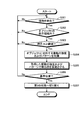
- FIG. 6 is a flowchart showing a processing procedure of contact operation control in the first state.
- FIG. 7 is a flowchart showing a processing procedure of contact operation control in the second state.
- the processing procedure shown in FIGS. 6 and 7 is realized by the control unit 10 executing the operation control program 9C.
- the control unit 10 determines whether a touch operation on the display unit 2B is detected as step S101. When the contact operation is not detected (No at Step S101), the control unit 10 re-executes the determination at Step S101.
- step S101 Yes
- the control part 10 determines whether the position where the contact operation was performed is in the display area of objects, such as an icon, as step S102.
- the control unit 10 re-executes Step S101 and the subsequent steps.
- step S102 When the position where the contact operation is performed is within the display area of the object (step S102, Yes), the control unit 10 acquires the vibration intensity and pattern corresponding to the object from the vibration definition data 9D as step S103. . In step S104, the control unit 10 causes the vibration unit 4 to vibrate the touch sensor 2A with the acquired intensity and pattern.
- step S105 the control unit 10 determines whether or not the reference position B1 is within the display area of the object on which the contact operation has been performed.
- the control unit 10 re-executes Step S101 and the subsequent steps.
- the control part 10 switches the mobile telephone terminal 1 to a 2nd state as step S106.
- the control unit 10 determines whether a touch operation on the display unit 2B has been detected as step S201.
- the control part 10 determines whether the position where the contact operation was performed is in the display area of objects, such as an icon, as step S202.
- the control unit 10 re-executes Step S201 and the subsequent steps.
- step S202 When the position where the contact operation is performed is within the display area of the object (step S202, Yes), the control unit 10 acquires the vibration intensity and pattern corresponding to the object from the vibration definition data 9D as step S203. . Then, in step S204, the control unit 10 causes the vibration unit 4 to vibrate the touch sensor 2A with the acquired intensity and pattern. Further, the control unit 10 activates a function associated with the object in step S205. And the control part 10 performs again after step S201.
- step S201 determines whether or not the state transition to the first state is performed as step S206.
- the state transition to the first state is performed, for example, when a contact operation is not detected for a predetermined period or more, or when a predetermined operation is detected by the input unit 3.
- the control unit 10 re-executes Step S201 and the subsequent steps.
- the control unit 10 switches the mobile phone terminal 1 to the first state as Step S207.
- the cellular phone terminal 1 is configured to vibrate the touch panel 2 with the strength and pattern according to the contact position when the contact operation is received in the first state. The user can be made to recognize the contact position.
- the aspect of this invention shown by said embodiment can be arbitrarily changed in the range which does not deviate from the summary of this invention.
- the present invention is applicable to an electronic device in which the display unit 2B and the touch sensor 2A are not superimposed. It can also be applied. In this case, the present invention is used to make the user recognize at which position on the touch sensor 2A the contact operation is performed.
- control unit 10 activates the function associated with the object when the position where the contact operation is performed is within the display area of the object in the second state.
- the invention vibrates the touch panel 2 with the intensity and pattern of vibration corresponding to the object in the first state when the position where the contact operation is performed is within the display area of the object in the first state.
- a function associated with the object may be activated.
- the reference position of the present invention may be the center position of the touch panel 2 (touch sensor 2A).
- the standard screen is displayed on the touch panel 2 in the first state.
- the screen displayed in the first state is not limited to the standard screen.
- vibration is generated according to the object. That's fine. Further, the intensity and pattern of vibration may be set for each screen.
- vibration may be generated according to the button.
- FIGS. 10 and 11 An example in which a virtual keyboard is displayed will be described with reference to FIGS. 10 and 11.
- FIG. 10 is a diagram illustrating an example in which a virtual keyboard 21 having a QWERTY layout is displayed on the touch panel 2.
- buttons corresponding to characters such as “A” and “B” and buttons corresponding to function keys such as “BS” are displayed.
- vibration may be generated according to the button.
- the reference position B2 is provided in the display area of the button corresponding to “F”
- the reference position B3 is provided in the display area of the button corresponding to “J”.
- the second state is set. You may migrate.
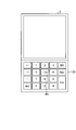
- FIG. 11 is a diagram showing an example in which a virtual keyboard 22 having a numeric keypad layout is displayed on the touch panel 2.
- buttons corresponding to numbers such as “1” and “2” and buttons corresponding to function keys such as “BS”.
- vibration may be generated according to the button.
- the virtual keyboard 22 with the numeric keypad it is preferable to provide the reference position B4 in the display area of the button corresponding to “5” arranged in the center among the buttons corresponding to the numbers.
- the reference position B4 By providing the reference position B4 in the display area of the button arranged at the center like the button corresponding to “5”, it becomes easy to grasp the positions of the other buttons after shifting to the second state. 10 and 11, for convenience of illustration, the reference positions B2, B3, and B4 are not located in the center of the button display area, but these reference positions are located in the center of the button display area. Is preferred.
- the vibration intensity and pattern are changed for each object in the first state, but the distance from the contact position to the reference position regardless of which region the contact position is included in.
- the intensity and pattern of vibration may be changed according to the direction. In this case, when a contact operation is detected within a predetermined distance from the reference position, the state may be changed to the second state.
- FIG. 8 is a flowchart showing a modification of the processing procedure of the contact operation control in the first state.
- the control unit 10 determines whether a touch operation on the display unit 2B has been detected as step S301. When the contact operation is not detected (No at Step S301), the control unit 10 re-executes the determination at Step S301.
- step S301 Yes
- the control part 10 determines whether the position where the contact operation was performed is in the display area of objects, such as an icon, as step S302.
- the control unit 10 re-executes Step S301 and the subsequent steps.
- step S302 When the position where the contact operation is performed is within the display area of the object (step S302, Yes), the control unit 10 determines whether the pressing force of the contact operation is equal to or greater than a threshold value as step S303. When the pressing force of the contact operation is not equal to or greater than the threshold value (No at Step S303), the control unit 10 re-executes Step S301 and the subsequent steps.
- step S303 When the pressing force of the contact operation is equal to or greater than the threshold (step S303, Yes), the control unit 10 acquires the vibration intensity and pattern corresponding to the object from the vibration definition data 9D as step S304. Then, in step S305, the control unit 10 causes the vibration unit 4 to vibrate the touch sensor 2A with the acquired intensity and pattern.
- step S306 the control unit 10 determines whether or not the reference position B1 is within the display area of the object on which the contact operation has been performed. When there is no reference position B1 (No at Step S306), the control unit 10 re-executes Step S301 and the subsequent steps. On the other hand, when there exists reference position B1 (step S306, Yes), the control part 10 switches the mobile telephone terminal 1 to a 2nd state as step S307.
- FIG. 9 is a flowchart showing a modification of the processing procedure of the contact operation control in the second state.
- the control unit 10 determines whether a touch operation on the display unit 2B is detected as step S401.
- a contact operation is detected (step S401, Yes)
- the control part 10 determines whether the position where the contact operation was performed is in the display area of objects, such as an icon, as step S402.
- the control unit 10 re-executes Step S401 and the subsequent steps.
- the control unit 10 determines whether the detected contact operation is the first operation as step S403.
- the first operation is an operation performed to confirm the contact position.
- the first operation is, for example, a single tap operation in which a tap operation is performed only once within a predetermined time.
- step S403 the control unit 10 acquires the vibration intensity and pattern corresponding to the object including the contact position from the vibration definition data 9D as step S404. .
- step S405 the control unit 10 causes the vibration unit 4 to vibrate the touch sensor 2A with the acquired intensity and pattern. Then, the control unit 10 re-executes Step S401 and the subsequent steps.
- the control unit 10 determines whether the detected contact operation is the second operation as step S406.
- the second operation is an operation performed to activate a function corresponding to the contact position.
- the second operation is, for example, a double tap operation in which the tap operation is performed twice within a predetermined time.
- step S406, Yes When the detected contact operation is the second operation (step S406, Yes), the control unit 10 activates a function associated with the object including the contact position as step S407. Then, the control unit 10 re-executes Step S401 and the subsequent steps.
- step S406, No When the detected contact operation is not the second operation (step S406, No), the control unit 10 re-executes step S401 and subsequent steps without activating any function.
- step S401 determines whether or not the state transition to the first state is performed as step S408.
- step S408 determines whether or not the state transition to the first state is performed.
- the user can confirm the contact position before activating the function. Malfunctions are less likely to occur.
- the combination of the first operation and the first operation in the above description is an example.
- the first operation is a long tap (long press) operation in which a finger is brought into contact with the touch panel 2 for a certain period of time.
- the second operation may be a single tap operation.
- the first operation may be an operation of bringing a finger into contact with the touch panel 2
- the second operation may be an operation of pressing the touch panel with a pressing force equal to or greater than a predetermined threshold.
Landscapes
- Engineering & Computer Science (AREA)
- General Engineering & Computer Science (AREA)
- Theoretical Computer Science (AREA)
- Human Computer Interaction (AREA)
- Physics & Mathematics (AREA)
- General Physics & Mathematics (AREA)
- User Interface Of Digital Computer (AREA)
- Position Input By Displaying (AREA)
Abstract
Description
まず、図1を参照しながら、本発明に係る電子機器の一実施形態である携帯電話端末1の外観について説明する。図1は、携帯電話端末1の外観を示す正面図である。図1に示すように、携帯電話端末1は、略六面体形状の筐体を有し、その筐体の表面にタッチパネル2と、入力部3と、スピーカ7と、マイク8とを備える。
2 タッチパネル
2A タッチセンサ(検出部)
2B 表示部
3 入力部
4 振動部
9 記憶部
9A メールプログラム
9B ブラウザプログラム
9C 操作制御プログラム
9D 振動定義データ
10 制御部
11 RAM
Claims (15)
- 表示部と、
前記表示部に対する接触を検出する検出部と、
前記検出部を振動させる振動部と、
前記表示部に対する接触による操作に基づく所定の処理を行わない第1の状態と、前記表示部に対する接触による操作に基づく所定の処理を行う第2の状態とを切り替える制御部と、を備え、
前記制御部は、前記第1の状態において、前記表示部上の所定の位置に対する接触が前記検出部により検出された場合に、当該接触に基づいて前記振動部により前記検出部を振動させるとともに、前記第1の状態から前記第2の状態に切り替える
ことを特徴とする電子機器。 - 前記表示部は、それぞれが機能と対応づけられた複数のオブジェクトを表示し、
前記制御部は、前記第1の状態から前記第2の状態へ切り替えた後に、前記表示部に表示された前記複数のオブジェクトのうち一のオブジェクトに対する接触が前記検出部により検出された場合に、当該接触による操作に基づく所定の処理として前記一のオブジェクトに対応づけられた機能を実行することを特徴とする請求項1に記載の電子機器。 - 前記制御部は、前記第1の状態において、前記複数のオブジェクトのうち前記表示部上の前記所定の位置に対応して配置される所定オブジェクトに対する接触が前記検出部により検出された場合に、前記所定オブジェクトに対応づけられた機能を実行することなく前記振動部により前記検出部を振動させるとともに、前記第1の状態から前記第2の状態に切り替えることを特徴とする請求項2に記載の電子機器。
- 前記制御部は、前記第1の状態から前記第2の状態へ切り替えた後に、前記一のオブジェクトに対する接触が前記検出部により検出された場合に、当該接触による操作に基づく所定の処理として、前記振動部により前記検出部を振動させるとともに、前記一のオブジェクトに対応づけられた機能を実行することを特徴とする請求項2または3に記載の電子機器。
- 前記制御部は、前記第1の状態から前記第2の状態へ切り替えた後に、前記一のオブジェクトに対する第1の接触が前記検出部により検出された場合に、当該第1の接触による操作に基づく所定の処理として前記振動部により前記検出部を振動させ、その後に、前記一のオブジェクトに対する第2の接触が前記検出部により検出された場合に、当該第2の接触による操作に基づく所定の処理として前記一のオブジェクトに対応づけられた機能を実行することを特徴とする請求項2または3に記載の電子機器。
- 前記制御部は、前記表示部上に表示されているオブジェクトごとに前記振動部による前記検出部の振動の強度またはパターンの少なくとも一方を変更することを特徴とする請求項2から5のいずれか1項に記載の電子機器。
- 前記制御部は、前記表示部上の前記所定の位置と前記表示部上に表示されているオブジェクトとの距離に応じて、前記振動部による前記検出部の振動の強度またはパターンの少なくとも一方を変更することを特徴とする請求項2から5のいずれか1項に記載の電子機器。
- 前記制御部は、前記所定の位置と近いオブジェクトほど、前記振動部による前記検出部を強く振動させることを特徴とする請求項7に記載の電子機器。
- 前記検出部は、前記表示部に対する接触において生じる押圧をさらに検出し、
前記制御部は、前記検出部により前記表示部上の前記所定の位置に対する接触であって所定の閾値以上の押圧による接触が検出された場合に、当該接触に基づいて前記振動部により前記検出部を振動させるとともに、前記第1の状態から前記第2の状態に切り替えることを特徴とする請求項1から8のいずれか1項に記載の電子機器。 - 前記所定の位置は、前記表示部の中央付近であることを特徴とする請求項1から9のいずれか1項に記載の電子機器。
- 前記表示部にQWERTY配列の仮想キーボードが表示されている場合、前記所定の位置は、「F」に対応するボタンの表示領域内と、「J」に対応するボタンの表示領域内とに設けられることを特徴とする請求項1から9のいずれか1項に記載の電子機器。
- 前記表示部にテンキー配列の仮想キーボードが表示されている場合、前記所定の位置は、「5」に対応するボタンの表示領域内に設けられることを特徴とする請求項1から9のいずれか1項に記載の電子機器。
- 表示部と、
前記表示部に対する接触を検出する検出部と、
前記検出部を振動させる振動部と、を備える電子機器によって実行される操作制御方法であって、
前記表示部に対する接触による操作に基づく所定の処理を行わない第1の状態において、前記検出部が、前記表示部に対する接触を検出するステップと、
前記検出部によって検出された接触に基づいて前記振動部が前記表示部を振動させるステップと、
前記第1の状態において、前記検出部が前記表示部上の所定の位置に対する接触を検出した場合に、前記第1の状態から、前記表示部に対する接触による操作に基づく所定の処理を行う第2の状態へ切り替えるステップと
を含むことを特徴とする操作制御方法。 - 表示部と、
前記表示部に対する接触を検出する検出部と、
前記検出部を振動させる振動部と、を備える電子機器に、
前記表示部に対する接触による操作に基づく所定の処理を行わない第1の状態において、前記検出部が、前記表示部に対する接触を検出するステップと、
前記検出部によって検出された接触に基づいて前記振動部が前記検出部を振動させるステップと、
前記第1の状態において、前記検出部が前記表示部上の所定の位置に対する接触を検出した場合に、前記第1の状態から、前記表示部に対する接触による操作に基づく所定の処理を行う第2の状態へ切り替えるステップと
を実行させることを特徴とする操作制御プログラム。 - タッチセンサと、
前記タッチセンサを振動させる振動部と、
前記タッチセンサに対する接触による操作に基づく所定の処理を行わない第1の状態と、前記タッチセンサに対する接触による操作に基づく所定の処理を行う第2の状態とを切り替える制御部と、を備え、
前記制御部は、前記第1の状態において、前記タッチセンサ上の所定の位置に対する接触が検出された場合に、当該接触に基づいて前記振動部により前記タッチセンサを振動させるとともに、前記第1の状態から前記第2の状態に切り替える
ことを特徴とする電子機器。
Priority Applications (2)
| Application Number | Priority Date | Filing Date | Title |
|---|---|---|---|
| US14/009,655 US9733708B2 (en) | 2011-04-06 | 2012-04-06 | Electronic device, operation control method, and operation control program |
| JP2013508953A JPWO2012137946A1 (ja) | 2011-04-06 | 2012-04-06 | 電子機器、操作制御方法および操作制御プログラム |
Applications Claiming Priority (2)
| Application Number | Priority Date | Filing Date | Title |
|---|---|---|---|
| JP2011-084790 | 2011-04-06 | ||
| JP2011084790 | 2011-04-06 |
Publications (1)
| Publication Number | Publication Date |
|---|---|
| WO2012137946A1 true WO2012137946A1 (ja) | 2012-10-11 |
Family
ID=46969334
Family Applications (1)
| Application Number | Title | Priority Date | Filing Date |
|---|---|---|---|
| PCT/JP2012/059583 Ceased WO2012137946A1 (ja) | 2011-04-06 | 2012-04-06 | 電子機器、操作制御方法および操作制御プログラム |
Country Status (3)
| Country | Link |
|---|---|
| US (1) | US9733708B2 (ja) |
| JP (1) | JPWO2012137946A1 (ja) |
| WO (1) | WO2012137946A1 (ja) |
Cited By (31)
| Publication number | Priority date | Publication date | Assignee | Title |
|---|---|---|---|---|
| WO2016185891A1 (ja) * | 2015-05-15 | 2016-11-24 | 株式会社東海理化電機製作所 | 触覚呈示装置 |
| JP2018142345A (ja) * | 2012-12-29 | 2018-09-13 | アップル インコーポレイテッドApple Inc. | 複数接触ジェスチャのために触知出力の生成を見合わせるためのデバイス、方法、及びグラフィカルユーザインタフェース |
| US10338772B2 (en) | 2015-03-08 | 2019-07-02 | Apple Inc. | Devices, methods, and graphical user interfaces for manipulating user interface objects with visual and/or haptic feedback |
| US10346030B2 (en) | 2015-06-07 | 2019-07-09 | Apple Inc. | Devices and methods for navigating between user interfaces |
| US10387029B2 (en) | 2015-03-08 | 2019-08-20 | Apple Inc. | Devices, methods, and graphical user interfaces for displaying and using menus |
| US10402073B2 (en) | 2015-03-08 | 2019-09-03 | Apple Inc. | Devices, methods, and graphical user interfaces for interacting with a control object while dragging another object |
| US10416800B2 (en) | 2015-08-10 | 2019-09-17 | Apple Inc. | Devices, methods, and graphical user interfaces for adjusting user interface objects |
| US10455146B2 (en) | 2015-06-07 | 2019-10-22 | Apple Inc. | Devices and methods for capturing and interacting with enhanced digital images |
| US10481690B2 (en) | 2012-05-09 | 2019-11-19 | Apple Inc. | Device, method, and graphical user interface for providing tactile feedback for media adjustment operations performed in a user interface |
| US10496260B2 (en) | 2012-05-09 | 2019-12-03 | Apple Inc. | Device, method, and graphical user interface for pressure-based alteration of controls in a user interface |
| US10592041B2 (en) | 2012-05-09 | 2020-03-17 | Apple Inc. | Device, method, and graphical user interface for transitioning between display states in response to a gesture |
| US10599331B2 (en) | 2015-03-19 | 2020-03-24 | Apple Inc. | Touch input cursor manipulation |
| US10613634B2 (en) | 2015-03-08 | 2020-04-07 | Apple Inc. | Devices and methods for controlling media presentation |
| US10620781B2 (en) | 2012-12-29 | 2020-04-14 | Apple Inc. | Device, method, and graphical user interface for moving a cursor according to a change in an appearance of a control icon with simulated three-dimensional characteristics |
| US10698598B2 (en) | 2015-08-10 | 2020-06-30 | Apple Inc. | Devices, methods, and graphical user interfaces for manipulating user interface objects with visual and/or haptic feedback |
| US10705718B2 (en) | 2015-06-07 | 2020-07-07 | Apple Inc. | Devices and methods for navigating between user interfaces |
| US10775999B2 (en) | 2012-05-09 | 2020-09-15 | Apple Inc. | Device, method, and graphical user interface for displaying user interface objects corresponding to an application |
| US10775994B2 (en) | 2012-05-09 | 2020-09-15 | Apple Inc. | Device, method, and graphical user interface for moving and dropping a user interface object |
| US10782871B2 (en) | 2012-05-09 | 2020-09-22 | Apple Inc. | Device, method, and graphical user interface for providing feedback for changing activation states of a user interface object |
| US10884591B2 (en) | 2012-05-09 | 2021-01-05 | Apple Inc. | Device, method, and graphical user interface for selecting object within a group of objects |
| US10884608B2 (en) | 2015-08-10 | 2021-01-05 | Apple Inc. | Devices, methods, and graphical user interfaces for content navigation and manipulation |
| US10908808B2 (en) | 2012-05-09 | 2021-02-02 | Apple Inc. | Device, method, and graphical user interface for displaying additional information in response to a user contact |
| US10915243B2 (en) | 2012-12-29 | 2021-02-09 | Apple Inc. | Device, method, and graphical user interface for adjusting content selection |
| US10969945B2 (en) | 2012-05-09 | 2021-04-06 | Apple Inc. | Device, method, and graphical user interface for selecting user interface objects |
| US11010027B2 (en) | 2012-05-09 | 2021-05-18 | Apple Inc. | Device, method, and graphical user interface for manipulating framed graphical objects |
| US11023116B2 (en) | 2012-05-09 | 2021-06-01 | Apple Inc. | Device, method, and graphical user interface for moving a user interface object based on an intensity of a press input |
| US11182017B2 (en) | 2015-08-10 | 2021-11-23 | Apple Inc. | Devices and methods for processing touch inputs based on their intensities |
| US11231831B2 (en) | 2015-06-07 | 2022-01-25 | Apple Inc. | Devices and methods for content preview based on touch input intensity |
| US11240424B2 (en) | 2015-06-07 | 2022-02-01 | Apple Inc. | Devices and methods for capturing and interacting with enhanced digital images |
| US12050761B2 (en) | 2012-12-29 | 2024-07-30 | Apple Inc. | Device, method, and graphical user interface for transitioning from low power mode |
| US12135871B2 (en) | 2012-12-29 | 2024-11-05 | Apple Inc. | Device, method, and graphical user interface for switching between user interfaces |
Families Citing this family (7)
| Publication number | Priority date | Publication date | Assignee | Title |
|---|---|---|---|---|
| CN115700434A (zh) | 2014-09-02 | 2023-02-07 | 苹果公司 | 用于可变触觉输出的语义框架 |
| JP6587941B2 (ja) * | 2016-01-14 | 2019-10-09 | 株式会社デンソーテン | 入力装置、表示装置、および、入力装置の振動状態検出方法 |
| DK179823B1 (en) | 2016-06-12 | 2019-07-12 | Apple Inc. | DEVICES, METHODS, AND GRAPHICAL USER INTERFACES FOR PROVIDING HAPTIC FEEDBACK |
| DK179657B1 (en) | 2016-06-12 | 2019-03-13 | Apple Inc. | Devices, methods and graphical user interfaces for providing haptic feedback |
| DK179278B1 (en) | 2016-09-06 | 2018-03-26 | Apple Inc | Devices, methods and graphical user interfaces for haptic mixing |
| DK201670720A1 (en) | 2016-09-06 | 2018-03-26 | Apple Inc | Devices, Methods, and Graphical User Interfaces for Generating Tactile Outputs |
| DK201770372A1 (en) | 2017-05-16 | 2019-01-08 | Apple Inc. | TACTILE FEEDBACK FOR LOCKED DEVICE USER INTERFACES |
Citations (3)
| Publication number | Priority date | Publication date | Assignee | Title |
|---|---|---|---|---|
| JP2009009412A (ja) * | 2007-06-28 | 2009-01-15 | Canon Inc | 情報提示装置及び情報提示方法 |
| JP2010244253A (ja) * | 2009-04-03 | 2010-10-28 | Sony Corp | 情報処理装置、通知方法、およびプログラム |
| JP2011048665A (ja) * | 2009-08-27 | 2011-03-10 | Sony Corp | 情報処理装置、情報処理方法、及びプログラム |
Family Cites Families (31)
| Publication number | Priority date | Publication date | Assignee | Title |
|---|---|---|---|---|
| JP2000137576A (ja) * | 1998-10-30 | 2000-05-16 | Nec Corp | タッチパネル式入力装置 |
| JP2000222129A (ja) | 1999-02-03 | 2000-08-11 | Harness Syst Tech Res Ltd | タッチパネルスイッチ |
| JP3949912B2 (ja) * | 2000-08-08 | 2007-07-25 | 株式会社エヌ・ティ・ティ・ドコモ | 携帯型電子機器、電子機器、振動発生器、振動による報知方法および報知制御方法 |
| FI112415B (fi) * | 2001-11-28 | 2003-11-28 | Nokia Oyj | Pietsosähköinen käyttöliittymä |
| JP3937982B2 (ja) * | 2002-08-29 | 2007-06-27 | ソニー株式会社 | 入出力装置および入出力装置を有する電子機器 |
| JP4717461B2 (ja) * | 2005-02-14 | 2011-07-06 | キヤノン株式会社 | 情報入力装置、情報入力方法及び情報入力プログラム |
| JP2007115157A (ja) * | 2005-10-24 | 2007-05-10 | Softbank Mobile Corp | キー操作感覚付与方法及び携帯情報装置 |
| US7657849B2 (en) | 2005-12-23 | 2010-02-02 | Apple Inc. | Unlocking a device by performing gestures on an unlock image |
| US8120584B2 (en) * | 2006-12-21 | 2012-02-21 | Cypress Semiconductor Corporation | Feedback mechanism for user detection of reference location on a sensing device |
| JP2008191086A (ja) * | 2007-02-07 | 2008-08-21 | Matsushita Electric Ind Co Ltd | ナビゲーション装置 |
| JP2009134473A (ja) * | 2007-11-29 | 2009-06-18 | Sony Corp | 押圧検知センサ、入力装置及び電子機器 |
| KR101498623B1 (ko) * | 2008-06-25 | 2015-03-04 | 엘지전자 주식회사 | 휴대 단말기 및 그 제어방법 |
| US8385885B2 (en) | 2008-10-17 | 2013-02-26 | Sony Ericsson Mobile Communications Ab | Method of unlocking a mobile electronic device |
| JP4875050B2 (ja) * | 2008-12-09 | 2012-02-15 | 京セラ株式会社 | 入力装置 |
| JP4633166B2 (ja) * | 2008-12-22 | 2011-02-16 | 京セラ株式会社 | 入力装置および入力装置の制御方法 |
| US20100214239A1 (en) * | 2009-02-23 | 2010-08-26 | Compal Electronics, Inc. | Method and touch panel for providing tactile feedback |
| JP5343871B2 (ja) * | 2009-03-12 | 2013-11-13 | 株式会社リコー | タッチパネル装置、これを含むタッチパネル付き表示装置、及びタッチパネル装置の制御方法 |
| JP2010224658A (ja) | 2009-03-19 | 2010-10-07 | Smk Corp | 操作入力装置 |
| KR101628782B1 (ko) * | 2009-03-20 | 2016-06-09 | 삼성전자주식회사 | 휴대용 단말기에서 복수의 진동자를 이용한 햅틱 기능 제공방법 및 장치 |
| JP5554517B2 (ja) * | 2009-04-22 | 2014-07-23 | 富士通コンポーネント株式会社 | タッチパネルの位置検出方法及びタッチパネル装置 |
| KR101598335B1 (ko) * | 2009-06-11 | 2016-02-29 | 엘지전자 주식회사 | 휴대 단말기 및 그 동작방법 |
| JP2011028635A (ja) | 2009-07-28 | 2011-02-10 | Sony Corp | 表示制御装置、表示制御方法およびコンピュータプログラム |
| JP2011048669A (ja) | 2009-08-27 | 2011-03-10 | Kyocera Corp | 入力装置 |
| JP5267388B2 (ja) * | 2009-08-31 | 2013-08-21 | ソニー株式会社 | 情報処理装置、情報処理方法およびプログラム |
| US8780055B2 (en) * | 2009-10-02 | 2014-07-15 | Blackberry Limited | Low power wakeup detection circuit and a portable electronic device having a low power wakeup detection circuit |
| KR101657963B1 (ko) * | 2009-12-08 | 2016-10-04 | 삼성전자 주식회사 | 단말기의 터치 면적 변화율에 따른 운용 방법 및 장치 |
| US20110248930A1 (en) * | 2010-04-08 | 2011-10-13 | Research In Motion Limited | Portable electronic device and method of controlling same to provide tactile feedback |
| US20110285517A1 (en) * | 2010-05-18 | 2011-11-24 | Tai-Seng Lam | Terminal apparatus and vibration notification method thereof |
| JP2011048848A (ja) * | 2010-10-27 | 2011-03-10 | Kyocera Corp | 入力装置および入力装置の制御方法 |
| JP5639489B2 (ja) * | 2011-01-25 | 2014-12-10 | キヤノン株式会社 | 情報処理装置及びその制御方法、プログラム、並びに記憶媒体 |
| US20120242584A1 (en) * | 2011-03-22 | 2012-09-27 | Nokia Corporation | Method and apparatus for providing sight independent activity reports responsive to a touch gesture |
-
2012
- 2012-04-06 WO PCT/JP2012/059583 patent/WO2012137946A1/ja not_active Ceased
- 2012-04-06 US US14/009,655 patent/US9733708B2/en not_active Expired - Fee Related
- 2012-04-06 JP JP2013508953A patent/JPWO2012137946A1/ja active Pending
Patent Citations (3)
| Publication number | Priority date | Publication date | Assignee | Title |
|---|---|---|---|---|
| JP2009009412A (ja) * | 2007-06-28 | 2009-01-15 | Canon Inc | 情報提示装置及び情報提示方法 |
| JP2010244253A (ja) * | 2009-04-03 | 2010-10-28 | Sony Corp | 情報処理装置、通知方法、およびプログラム |
| JP2011048665A (ja) * | 2009-08-27 | 2011-03-10 | Sony Corp | 情報処理装置、情報処理方法、及びプログラム |
Cited By (57)
| Publication number | Priority date | Publication date | Assignee | Title |
|---|---|---|---|---|
| US11354033B2 (en) | 2012-05-09 | 2022-06-07 | Apple Inc. | Device, method, and graphical user interface for managing icons in a user interface region |
| US10775994B2 (en) | 2012-05-09 | 2020-09-15 | Apple Inc. | Device, method, and graphical user interface for moving and dropping a user interface object |
| US12340075B2 (en) | 2012-05-09 | 2025-06-24 | Apple Inc. | Device, method, and graphical user interface for selecting user interface objects |
| US10908808B2 (en) | 2012-05-09 | 2021-02-02 | Apple Inc. | Device, method, and graphical user interface for displaying additional information in response to a user contact |
| US12067229B2 (en) | 2012-05-09 | 2024-08-20 | Apple Inc. | Device, method, and graphical user interface for providing feedback for changing activation states of a user interface object |
| US11314407B2 (en) | 2012-05-09 | 2022-04-26 | Apple Inc. | Device, method, and graphical user interface for providing feedback for changing activation states of a user interface object |
| US12045451B2 (en) | 2012-05-09 | 2024-07-23 | Apple Inc. | Device, method, and graphical user interface for moving a user interface object based on an intensity of a press input |
| US10884591B2 (en) | 2012-05-09 | 2021-01-05 | Apple Inc. | Device, method, and graphical user interface for selecting object within a group of objects |
| US11947724B2 (en) | 2012-05-09 | 2024-04-02 | Apple Inc. | Device, method, and graphical user interface for providing tactile feedback for operations performed in a user interface |
| US10481690B2 (en) | 2012-05-09 | 2019-11-19 | Apple Inc. | Device, method, and graphical user interface for providing tactile feedback for media adjustment operations performed in a user interface |
| US10496260B2 (en) | 2012-05-09 | 2019-12-03 | Apple Inc. | Device, method, and graphical user interface for pressure-based alteration of controls in a user interface |
| US10996788B2 (en) | 2012-05-09 | 2021-05-04 | Apple Inc. | Device, method, and graphical user interface for transitioning between display states in response to a gesture |
| US11010027B2 (en) | 2012-05-09 | 2021-05-18 | Apple Inc. | Device, method, and graphical user interface for manipulating framed graphical objects |
| US10969945B2 (en) | 2012-05-09 | 2021-04-06 | Apple Inc. | Device, method, and graphical user interface for selecting user interface objects |
| US10592041B2 (en) | 2012-05-09 | 2020-03-17 | Apple Inc. | Device, method, and graphical user interface for transitioning between display states in response to a gesture |
| US11221675B2 (en) | 2012-05-09 | 2022-01-11 | Apple Inc. | Device, method, and graphical user interface for providing tactile feedback for operations performed in a user interface |
| US11068153B2 (en) | 2012-05-09 | 2021-07-20 | Apple Inc. | Device, method, and graphical user interface for displaying user interface objects corresponding to an application |
| US11023116B2 (en) | 2012-05-09 | 2021-06-01 | Apple Inc. | Device, method, and graphical user interface for moving a user interface object based on an intensity of a press input |
| US10775999B2 (en) | 2012-05-09 | 2020-09-15 | Apple Inc. | Device, method, and graphical user interface for displaying user interface objects corresponding to an application |
| US10942570B2 (en) | 2012-05-09 | 2021-03-09 | Apple Inc. | Device, method, and graphical user interface for providing tactile feedback for operations performed in a user interface |
| US10782871B2 (en) | 2012-05-09 | 2020-09-22 | Apple Inc. | Device, method, and graphical user interface for providing feedback for changing activation states of a user interface object |
| JP2018142345A (ja) * | 2012-12-29 | 2018-09-13 | アップル インコーポレイテッドApple Inc. | 複数接触ジェスチャのために触知出力の生成を見合わせるためのデバイス、方法、及びグラフィカルユーザインタフェース |
| US10620781B2 (en) | 2012-12-29 | 2020-04-14 | Apple Inc. | Device, method, and graphical user interface for moving a cursor according to a change in an appearance of a control icon with simulated three-dimensional characteristics |
| US10437333B2 (en) | 2012-12-29 | 2019-10-08 | Apple Inc. | Device, method, and graphical user interface for forgoing generation of tactile output for a multi-contact gesture |
| US12050761B2 (en) | 2012-12-29 | 2024-07-30 | Apple Inc. | Device, method, and graphical user interface for transitioning from low power mode |
| US12135871B2 (en) | 2012-12-29 | 2024-11-05 | Apple Inc. | Device, method, and graphical user interface for switching between user interfaces |
| US10915243B2 (en) | 2012-12-29 | 2021-02-09 | Apple Inc. | Device, method, and graphical user interface for adjusting content selection |
| US10613634B2 (en) | 2015-03-08 | 2020-04-07 | Apple Inc. | Devices and methods for controlling media presentation |
| US11112957B2 (en) | 2015-03-08 | 2021-09-07 | Apple Inc. | Devices, methods, and graphical user interfaces for interacting with a control object while dragging another object |
| US12436662B2 (en) | 2015-03-08 | 2025-10-07 | Apple Inc. | Devices, methods, and graphical user interfaces for manipulating user interface objects with visual and/or haptic feedback |
| US10860177B2 (en) | 2015-03-08 | 2020-12-08 | Apple Inc. | Devices, methods, and graphical user interfaces for manipulating user interface objects with visual and/or haptic feedback |
| US10338772B2 (en) | 2015-03-08 | 2019-07-02 | Apple Inc. | Devices, methods, and graphical user interfaces for manipulating user interface objects with visual and/or haptic feedback |
| US10387029B2 (en) | 2015-03-08 | 2019-08-20 | Apple Inc. | Devices, methods, and graphical user interfaces for displaying and using menus |
| US10402073B2 (en) | 2015-03-08 | 2019-09-03 | Apple Inc. | Devices, methods, and graphical user interfaces for interacting with a control object while dragging another object |
| US11977726B2 (en) | 2015-03-08 | 2024-05-07 | Apple Inc. | Devices, methods, and graphical user interfaces for interacting with a control object while dragging another object |
| US10599331B2 (en) | 2015-03-19 | 2020-03-24 | Apple Inc. | Touch input cursor manipulation |
| US11550471B2 (en) | 2015-03-19 | 2023-01-10 | Apple Inc. | Touch input cursor manipulation |
| US11054990B2 (en) | 2015-03-19 | 2021-07-06 | Apple Inc. | Touch input cursor manipulation |
| WO2016185891A1 (ja) * | 2015-05-15 | 2016-11-24 | 株式会社東海理化電機製作所 | 触覚呈示装置 |
| US10705718B2 (en) | 2015-06-07 | 2020-07-07 | Apple Inc. | Devices and methods for navigating between user interfaces |
| US12346550B2 (en) | 2015-06-07 | 2025-07-01 | Apple Inc. | Devices and methods for capturing and interacting with enhanced digital images |
| US11231831B2 (en) | 2015-06-07 | 2022-01-25 | Apple Inc. | Devices and methods for content preview based on touch input intensity |
| US11240424B2 (en) | 2015-06-07 | 2022-02-01 | Apple Inc. | Devices and methods for capturing and interacting with enhanced digital images |
| US10841484B2 (en) | 2015-06-07 | 2020-11-17 | Apple Inc. | Devices and methods for capturing and interacting with enhanced digital images |
| US10346030B2 (en) | 2015-06-07 | 2019-07-09 | Apple Inc. | Devices and methods for navigating between user interfaces |
| US11681429B2 (en) | 2015-06-07 | 2023-06-20 | Apple Inc. | Devices and methods for capturing and interacting with enhanced digital images |
| US11835985B2 (en) | 2015-06-07 | 2023-12-05 | Apple Inc. | Devices and methods for capturing and interacting with enhanced digital images |
| US10455146B2 (en) | 2015-06-07 | 2019-10-22 | Apple Inc. | Devices and methods for capturing and interacting with enhanced digital images |
| US11327648B2 (en) | 2015-08-10 | 2022-05-10 | Apple Inc. | Devices, methods, and graphical user interfaces for manipulating user interface objects with visual and/or haptic feedback |
| US10416800B2 (en) | 2015-08-10 | 2019-09-17 | Apple Inc. | Devices, methods, and graphical user interfaces for adjusting user interface objects |
| US11740785B2 (en) | 2015-08-10 | 2023-08-29 | Apple Inc. | Devices, methods, and graphical user interfaces for manipulating user interface objects with visual and/or haptic feedback |
| US10754542B2 (en) | 2015-08-10 | 2020-08-25 | Apple Inc. | Devices, methods, and graphical user interfaces for manipulating user interface objects with visual and/or haptic feedback |
| US10963158B2 (en) | 2015-08-10 | 2021-03-30 | Apple Inc. | Devices, methods, and graphical user interfaces for manipulating user interface objects with visual and/or haptic feedback |
| US11182017B2 (en) | 2015-08-10 | 2021-11-23 | Apple Inc. | Devices and methods for processing touch inputs based on their intensities |
| US10698598B2 (en) | 2015-08-10 | 2020-06-30 | Apple Inc. | Devices, methods, and graphical user interfaces for manipulating user interface objects with visual and/or haptic feedback |
| US12386501B2 (en) | 2015-08-10 | 2025-08-12 | Apple Inc. | Devices, methods, and graphical user interfaces for manipulating user interface objects with visual and/or haptic feedback |
| US10884608B2 (en) | 2015-08-10 | 2021-01-05 | Apple Inc. | Devices, methods, and graphical user interfaces for content navigation and manipulation |
Also Published As
| Publication number | Publication date |
|---|---|
| JPWO2012137946A1 (ja) | 2014-07-28 |
| US20140024414A1 (en) | 2014-01-23 |
| US9733708B2 (en) | 2017-08-15 |
Similar Documents
| Publication | Publication Date | Title |
|---|---|---|
| WO2012137946A1 (ja) | 電子機器、操作制御方法および操作制御プログラム | |
| JP5753432B2 (ja) | 携帯電子機器 | |
| CA2739225C (en) | Method of providing tactile feedback and electronic device | |
| US8786562B2 (en) | Mobile electronic device, control method, and storage medium storing control program | |
| US8451255B2 (en) | Method of providing tactile feedback and electronic device | |
| US8466889B2 (en) | Method of providing tactile feedback and electronic device | |
| US20100201652A1 (en) | Embedded piezoelectric elements in touch panels | |
| EP2375309A1 (en) | Handheld device with localized delays for triggering tactile feedback | |
| US20110248839A1 (en) | Portable electronic device and method of controlling same | |
| KR101250638B1 (ko) | 휴대용 전자 디바이스 및 이의 제어 방법 | |
| US20110248929A1 (en) | Electronic device and method of controlling same | |
| JP5679782B2 (ja) | 携帯電子機器、画面制御方法および画面制御プログラム | |
| EP3211510B1 (en) | Portable electronic device and method of providing haptic feedback | |
| JP2011128704A (ja) | 携帯電子機器及び携帯電子機器の制御方法 | |
| JP2012174248A (ja) | 携帯電子機器、接触操作制御方法および接触操作制御プログラム | |
| CA2739126C (en) | Method of providing tactile feedback and electronic device | |
| JP5725903B2 (ja) | 電子機器、接触操作制御プログラムおよび接触操作制御方法 | |
| JP2012208614A (ja) | 携帯電子機器 | |
| JP5732219B2 (ja) | 電子機器 | |
| JP5995405B2 (ja) | 携帯電子機器、表示切替方法及び表示切替プログラム | |
| JP6133451B2 (ja) | 携帯電子機器、画面制御方法および画面制御プログラム | |
| KR101147730B1 (ko) | 가상 키보드 제공 단말 및 그 방법 | |
| CA2719844A1 (en) | Portable electronic device and method of controlling same |
Legal Events
| Date | Code | Title | Description |
|---|---|---|---|
| 121 | Ep: the epo has been informed by wipo that ep was designated in this application |
Ref document number: 12768005 Country of ref document: EP Kind code of ref document: A1 |
|
| ENP | Entry into the national phase |
Ref document number: 2013508953 Country of ref document: JP Kind code of ref document: A |
|
| WWE | Wipo information: entry into national phase |
Ref document number: 14009655 Country of ref document: US |
|
| NENP | Non-entry into the national phase |
Ref country code: DE |
|
| 122 | Ep: pct application non-entry in european phase |
Ref document number: 12768005 Country of ref document: EP Kind code of ref document: A1 |