WO2012138064A2 - 다채널 pwm 파형 측정기 - Google Patents
다채널 pwm 파형 측정기 Download PDFInfo
- Publication number
- WO2012138064A2 WO2012138064A2 PCT/KR2012/001978 KR2012001978W WO2012138064A2 WO 2012138064 A2 WO2012138064 A2 WO 2012138064A2 KR 2012001978 W KR2012001978 W KR 2012001978W WO 2012138064 A2 WO2012138064 A2 WO 2012138064A2
- Authority
- WO
- WIPO (PCT)
- Prior art keywords
- pwm waveform
- measurement
- inverter
- signal
- converter
- Prior art date
- Legal status (The legal status is an assumption and is not a legal conclusion. Google has not performed a legal analysis and makes no representation as to the accuracy of the status listed.)
- Ceased
Links
Images




Classifications
-
- G—PHYSICS
- G01—MEASURING; TESTING
- G01R—MEASURING ELECTRIC VARIABLES; MEASURING MAGNETIC VARIABLES
- G01R31/00—Arrangements for testing electric properties; Arrangements for locating electric faults; Arrangements for electrical testing characterised by what is being tested not provided for elsewhere
- G01R31/28—Testing of electronic circuits, e.g. by signal tracer
-
- G—PHYSICS
- G01—MEASURING; TESTING
- G01R—MEASURING ELECTRIC VARIABLES; MEASURING MAGNETIC VARIABLES
- G01R29/00—Arrangements for measuring or indicating electric quantities not covered by groups G01R19/00 - G01R27/00
- G01R29/02—Measuring characteristics of individual pulses, e.g. deviation from pulse flatness, rise time or duration
- G01R29/023—Measuring pulse width
Definitions
- the present invention relates to a multi-channel PWM waveform measuring device, and more particularly, it is possible to safely and quickly recover a servo drive by minimizing the loss of expensive power semiconductor elements and reducing the damage of the servo drive PCB during the diagnosis of a complicated servo drive.
- One multi-channel PWM waveform meter One multi-channel PWM waveform meter.
- the measurement using an oscilloscope is not only an engineer's area, but it is difficult to say that it is only an engineer who has acquired expertise in the equipment, and there are many measuring points in the servo drive. And skills are needed.
- the present invention has been made in view of the above problems, and it is possible to recover servo drives safely and quickly by minimizing the loss of expensive power semiconductor elements and minimizing damage to the servo drive PCB during the diagnosis of complex servo drives. Its purpose is to provide a multichannel PWM waveform meter.
- Another object of the present invention is to provide a multi-channel PWM waveform measuring device which is preconfigured to check the condition and damage of the servo drive PCB different for each manufacturer.
- the multi-channel PWM waveform measuring device for achieving the above object, in the multi-channel PWM waveform measuring device for checking the PWM output state of the main control board of the servo drive, the removable servo drive of the inspection target
- the PCB of the inverter is connected to the base terminal of the transistor provided in the inverter and the converter installed by the connector, and communicates the measurement signal through a plurality of pre-installed probes corresponding to the measuring points of the inverter and the converter for measuring the PWM waveform, respectively.
- a signal processor for collecting a measurement signal through the communication cable and outputting a measurement signal of a probe connected to an on switch when the switch is turned on by an operation button;
- a signal output unit configured to output a PWM waveform indicating a measurement signal input from the signal processor as a change in input voltage over time on a screen.
- the signal processor has a pin connector connected to the communication cable, characterized in that for collecting the measurement signal output from the probe.
- the signal output unit a personal computer; And an oscilloscope connected to the personal computer to receive a control command from the personal computer and display the measured signal as a PWM waveform for checking the PCB state of the servo drive.
- the oscilloscope is characterized in that any one of an analog oscilloscope, a digital type oscilloscope or a USB oscilloscope.
- the signal processor comprises: a multiplexer for selectively outputting any one of the measurement signals collected by the operation of the operation button; And a switch unit having one-to-one switches corresponding to the plurality of probes, the switch unit being switched on by the multiplexer and outputting a measurement signal connected to the on-state switch among the measurement signals collected from the probes.
- the switch unit characterized in that consisting of a plurality of relays.
- the measuring jig may be manufactured in various ways in consideration of the measuring points of the inverter and the converter for each manufacturer in consideration of the fact that the position and the number of transistors provided in the inverter and the converter are different for each manufacturer of the servo drive.
- the plurality of probes is characterized in that the number corresponding to the number of transistors constituting the inverter and the converter.
- the present invention has the effect of safely and quickly recovering the servo drive by reducing the loss of expensive power semiconductor elements and reducing the damage of the servo drive PCB in the process of diagnosing a complicated servo drive.
- FIG. 1 is a block diagram showing a typical closed loop system.
- FIG. 2 is a block diagram showing a multi-channel PWM waveform measuring instrument according to an embodiment of the present invention.
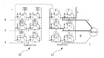
- FIG. 3 is an exemplary view for explaining an inverter and a converter provided in the measurement jig in FIG. 2.
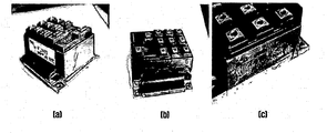
- Figure 4 is an exemplary view showing an inverter and a converter destroyed by the abnormal phenomenon.
- 5A and 5B are exemplary views for explaining a signal processor in FIG.
- Figure 6 is an exemplary view showing a measurement waveform through the multi-channel PWM waveform measuring instrument according to an embodiment of the present invention.
- the multi-channel pulse width modulation (PWM) waveform measuring device is 1. a defect in the drive sequence switching caused by the damage of the TR (transistor) module of the spindle drive, 2. the gate driving circuit of the converter base board. There are five reasons for the abnormal operation of furnace, 3. Main control board and interface contact failure, 4. Over Current, 5. Main control board failure.
- a measurement signal refers to a signal measured by a probe preset according to a measurement point of an inverter and a converter to measure a PWM waveform to check the state of the main control board of the servo drive.
- the measurement signal output corresponding to the column or row of the device will be used immediately means a measurement signal that can determine which column or row in the main control panel of the servo drive is defective.
- the limited channel oscilloscope performs difficult PWM analysis of waveform analysis and analysis and diagnostics of the switching sequence of the inverter drive.
- the multi-channel PWM waveform measuring device has a measurement time of less than 10 minutes, and the number of measuring channels corresponds to the number of transistors constituting the inverter and the converter, and simply and easily measures the PWM waveforms of the inverter and the converter. It is very safe to use the measuring jig. This reduces the measurement time compared to conventional oscilloscopes and differs from conventional oscilloscopes, which can measure only the number of channels measured at the time of shipment.
- the multi-channel PWM waveform measuring device of the present invention is very safe, simple, and easy compared to a conventional oscilloscope which is dangerous for manual measurement of a high voltage part after power is applied for measuring a PWM waveform.
- the main control board of the PCB performing the control operation is composed of a signal generator for generating a PWM signal, a signal driver, and an automatic controller for detecting and feeding back an output signal from a sensor to drive a servo spindle motor.
- Control action means that when driving the spindle motor, the automatic controller compares the target value, which is a reference input, with the actual value, which is output from the plant. Error value) is calculated and control signal is generated to reduce the calculated error value to 0 or very small value to make the optimum number of rotations desired by the user. In this way, the process in which the automatic controller generates the control signal is defined as "control operation".
- a general servo mechanism is a closed loop system as shown in FIG. 1, and the closed loop system is controlled with three components: a command, a feedback (feedback signal), and an error.
- the command is the target value
- the feedback is the actual data
- the error is simply the difference between the target value and the actual value.
- FIG. 2 is a block diagram showing a multi-channel PWM waveform measuring instrument according to an embodiment of the present invention.
- the multi-channel PWM waveform measuring device 100 includes a measuring jig 10, a signal processor 20, a signal output unit 30, and the like.
- the measuring jig 10 is connected to the inverter 11 and the converter 13 that are installed in the main control plate of the detachable servo drive to be inspected through a connector provided on the upper part of the measuring jig 10. Thereafter, after acquiring a measurement signal through a plurality of pre-installed probes 15 corresponding to the measurement points of the inverter 11 and the converter 13 for measuring the PWM waveform, the obtained measurement signal is connected with a communication cable. Output to the signal processor 20.
- the plurality of probes includes a number corresponding to the number of transistors constituting the inverter and the converter.
- the measuring jig 10 is used as it is in the finished product of the servo drive, but is produced by connecting a plurality of probes to a plurality of measuring points for measuring the PWM waveform of the inverter and the converter.
- the measurement jig 10 is the position and the number of the inverter 11 and the converter 13 is different from each manufacturer of the servo drive in consideration of the position of the inverter and the converter by the manufacturer and the base end of the TR provided in the inverter and the converter
- the measuring jig 10 may be manufactured in various ways in consideration of the measuring point according to the position.
- the configuration and circuit structure of the inverter 11 and the converter 13 will be described later.
- the signal processor 20 collects a measurement signal through a communication cable (not shown) and outputs a measurement signal of a probe connected to a switch in an on state when the switch is turned on by an operation button.
- the signal processor 20 is provided with a multiplexer (not shown) for selectively outputting any one of the measurement signals collected by the operation of the operation button, and a switch in a one-to-one correspondence with the multiple probes.
- a switch unit (not shown) that is switched on and outputs a measurement signal connected to a switch in an on state among measurement signals collected from the plurality of probes 15.
- the switch unit includes a plurality of relays.
- the signal processor 20 includes a pin connector (not shown) connected to a communication cable to collect a measurement signal output from the probe 15.
- the configuration of the signal processor 20 will be described later in detail.
- the signal output unit 30 outputs the measurement signal input from the signal processor 20 as a PWM waveform on the screen.
- the PWM waveform is represented as a change in the input voltage over time.
- the signal output unit 30 is connected to a personal computer and a personal computer, an oscilloscope for displaying a measurement signal received by receiving a control command from the personal computer as a PWM waveform for checking the state of the main control board of the servo drive. It includes.
- the oscilloscope is any one of an analog oscilloscope, a digital oscilloscope, or a USB oscilloscope.
- FIG. 3 is an exemplary view for explaining an inverter and a converter provided in the measurement jig in FIG. 2.
- a thick line on the side of the inverter 11 is an example, and shows a loop in which TR 1 and TR 6 are turned on according to a sequence.
- the measuring jig 10 of the present invention rectifies AC three-phase AC power (R, S, T) and converts the DC into a converter 13 and a DC voltage output from the converter 13. It is configured to include an inverter 11 that receives the input and converts to an AC voltage to have the voltage and frequency required for driving the motor using a PWM method.
- the measurement points are previously measured so as to correspond one-to-one to the base end of the TR, which is the measurement point of TR (which has 12 measurement points in FIG. 2).
- the probe 15 is set according to the number of.
- the TR is destroyed in the following cases.
- a gate signal is applied to, for example, six switches to form a rotating magnetic field in the spindle motor to rotate the motor.
- the rotation may be irregular or the torque may be affected and an overcurrent phenomenon may occur.
- the TR module is destroyed and, in severe cases, severely damages the servo driver PCB.
- 5A and 5B are exemplary views for explaining a signal processor in FIG. 2.
- the signal processor 20 collects all the measured signals measured from the measuring points of the inverter 11 and the converter 13 through the probe 15 connected to the pin connector. Then, one of the measurement signals collected through the multiplex 21 is selected according to the operation of the operation button.
- the current flows to the one of the relay coils (any one of C1 to C12..n) selected from the plurality of relay coils by the multiplexer 21.
- the relay (switch) of the switch unit 23 corresponding to the relay coil through which the current flows is turned on (short) to transmit the measurement signal to the oscilloscope of the signal output unit 30.
- the signal output unit 30 receives the measurement signal and displays the measured PWM waveform on the screen, and the inspector checks the abnormality of the servo drive.
- FIG. 6 is an exemplary view showing a measurement waveform through a multi-channel PWM waveform measuring device according to an embodiment of the present invention.
- FIG. 6A illustrates a normal waveform
- FIG. 6B illustrates an abnormal waveform, which is a waveform displayed through the signal output unit 30.
- the switching voltage of + 1.5V to 2V and the voltage of -1.5 to 2V are repeated up and down with respect to 0V.
- the positive voltage is stable at 1.5 to 2V, but the negative voltage cannot be switched to 0.8V and thus is determined as a bad waveform.
Landscapes
- Physics & Mathematics (AREA)
- General Physics & Mathematics (AREA)
- Engineering & Computer Science (AREA)
- General Engineering & Computer Science (AREA)
- Inverter Devices (AREA)
- Tests Of Electronic Circuits (AREA)
- Testing Electric Properties And Detecting Electric Faults (AREA)
Abstract
Description
| 측정방법 | 측정시간 | 측정 채널수 | 작업 난이도 | 안전성 |
| 오실로스코프 | 30분~2시간 | 제한적(출하 시 정해진 채널 2 또는 4채널) | 다소 어려움 | 전원 인가 후 고압부 수동 측정으로 다소 위험 |
| 다채널 PWM 파형 측정기 | 10분 이내 | 1~N개(N은 setting 가능 수) | 간단하고 쉬움 | 측정지그 사용으로 매우 안전 |
Claims (8)
- 서보 드라이브의 주 제어기판의 PWM(Pulse Width Modulation) 출력상태를 점검하기 위한 다채널 PWM 파형 측정기에 있어서,인버터와 컨버터를 포함하고, 착탈 가능한 서보 드라이브의 PCB가 장착되는 커넥터를 구비하고, 이 커넥터를 통해 상기 인버터와 컨버터가 상기 PCB에 연결되며, PWM 파형을 측정하기 위한 복수의 프로브를 구비하되, 상기 복수의 프로브는 상기 인버터와 컨버터에서 미리 정해진 측정 포인트에 설치되어 있으며, 상기 복수의 프로브를 통해 측정된 신호를 통신 케이블로 출력하는 측정 지그;상기 측정 지그의 상기 통신 케이블을 통해 측정 신호를 수집하며, 조작버튼에 의해 스위치 온(ON)상태시, 상기 복수의 프로브 중에서 온 상태인 순간에 연결되어 있는 프로브의 측정신호를 출력하는 신호 처리기; 및상기 신호 처리기로부터 입력되는 측정신호를 PWM 파형으로 화면에 출력하는 신호 출력부를 포함하는 것을 특징으로 하는 다채널 PWM 파형 측정기.
- 제1 항에 있어서, 상기 신호 처리기는,통신 케이블과 연결되는 핀 커넥터를 구비하여, 프로브에서 출력되는 측정 신호를 수집하는 것을 특징으로 하는 다채널 PWM 파형 측정기.
- 제1 항에 있어서, 상기 신호 출력부는,개인용 컴퓨터; 및상기 개인용 컴퓨터와 연결되어, 개인용 컴퓨터로부터 제어명령을 입력받아 입력되는 측정신호를 서보 드라이브의 PCB 상태를 점검하기 위한 PWM 파형으로 표시하는 오실로스코프를 포함하는 것을 특징으로 하는 다채널 PWM 파형 측정기.
- 제3 항에 있어서, 상기 오실로스코프는,아날로그 타입의 오실로 스코프, 디지털 타입의 오실로 스코프 또는 USB 오실로 스코프 중 어느 하나인 것을 특징으로 하는 다채널 PWM 파형 측정기.
- 제1 항에 있어서, 상기 신호 처리기는,조작버튼의 조작에 의해 수집된 측정신호 중 어느 하나를 선택적으로 출력하는 멀티플렉서; 및복수의 프로브에 일대일 대응하게 스위치를 구비하여, 상기 멀티플렉서에 의해 스위칭 온되어, 상기 프로브로부터 수집한 측정 신호중 온상태의 스위치에 대응하여 연결된 측정 신호를 출력하는 스위치부를 포함하는 것을 특징으로 하는 다채널 PWM 파형 측정기.
- 제5 항에 있어서, 상기 스위치부는,복수의 릴레이로 이루어진 것을 특징으로 하는 다채널 PWM 파형 측정기.
- 제1 항에 있어서, 상기 측정 지그는,인버터와 컨버터에 구비되는 트랜지스터의 위치 및 개수가 서보 드라이브의 제조사별로 상이한 점을 감안하여 제조사별 인버터와 컨버터의 측정 포인트를 고려하여 다양하게 제작되는 것을 특징으로 하는 다채널 PWM 파형 측정기.
- 제1 항에 있어서, 상기 복수의 프로브는,인버터와 컨버터를 이루는 트랜지스터 개수에 대응하는 개수로 이루어진 것을 특징으로 하는 다채널 PWM 파형 측정기.
Priority Applications (2)
| Application Number | Priority Date | Filing Date | Title |
|---|---|---|---|
| JP2014503588A JP2014513288A (ja) | 2011-04-06 | 2012-03-20 | 多チャンネルpwm波形測定器 |
| US14/009,779 US20140021938A1 (en) | 2011-04-06 | 2012-03-20 | Multi-channel pwm waveform measuring device |
Applications Claiming Priority (2)
| Application Number | Priority Date | Filing Date | Title |
|---|---|---|---|
| KR1020110031608A KR101089846B1 (ko) | 2011-04-06 | 2011-04-06 | 다채널 pwm 파형 측정기 |
| KR10-2011-0031608 | 2011-04-06 |
Publications (2)
| Publication Number | Publication Date |
|---|---|
| WO2012138064A2 true WO2012138064A2 (ko) | 2012-10-11 |
| WO2012138064A3 WO2012138064A3 (ko) | 2012-12-06 |
Family
ID=45505631
Family Applications (1)
| Application Number | Title | Priority Date | Filing Date |
|---|---|---|---|
| PCT/KR2012/001978 Ceased WO2012138064A2 (ko) | 2011-04-06 | 2012-03-20 | 다채널 pwm 파형 측정기 |
Country Status (4)
| Country | Link |
|---|---|
| US (1) | US20140021938A1 (ko) |
| JP (1) | JP2014513288A (ko) |
| KR (1) | KR101089846B1 (ko) |
| WO (1) | WO2012138064A2 (ko) |
Families Citing this family (5)
| Publication number | Priority date | Publication date | Assignee | Title |
|---|---|---|---|---|
| EP2972667A4 (en) * | 2013-03-15 | 2016-11-09 | Defelsko Corp | PROBE COMMUNICATION MODULE AND COMPUTER DEVICE |
| RU178677U1 (ru) * | 2017-09-28 | 2018-04-17 | ФЕДЕРАЛЬНОЕ ГОСУДАРСТВЕННОЕ БЮДЖЕТНОЕ ОБРАЗОВАТЕЛЬНОЕ УЧРЕЖДЕНИЕ ВЫСШЕГО ОБРАЗОВАНИЯ "Брянский государственный технический университет" | Тестер ШИМ контроллеров |
| CN112217705A (zh) * | 2020-09-18 | 2021-01-12 | 浙江伊控动力系统有限公司 | 数据传输电路、集成式逆变器和汽车 |
| CN113300902B (zh) * | 2021-03-29 | 2022-05-20 | 明峰医疗系统股份有限公司 | 多通道脉冲宽度测量及数据传输处理方法 |
| CN114878879B (zh) * | 2022-07-11 | 2022-09-30 | 天津普智芯网络测控技术有限公司 | 一种适用于不同通信端口的检测脉冲调制和使用方法 |
Family Cites Families (7)
| Publication number | Priority date | Publication date | Assignee | Title |
|---|---|---|---|---|
| US6477476B1 (en) * | 1999-12-06 | 2002-11-05 | Koninklijke Philips Electronics N.V. | Periodic-signal analysis via correlation |
| KR20030069530A (ko) * | 2002-02-21 | 2003-08-27 | 한국과학기술원 | 적외선 펄스폭변조 구동방식을 이용한 위치 감지시스템 및방법 |
| JP2006214834A (ja) | 2005-02-02 | 2006-08-17 | Seiko Epson Corp | 検査プローブ、光学パネルの検査装置、光学パネルの検査方法 |
| CN101317099B (zh) * | 2005-11-10 | 2012-06-27 | 日本发条株式会社 | 接触单元以及检查系统 |
| KR101539359B1 (ko) * | 2009-02-05 | 2015-07-27 | 삼성디스플레이 주식회사 | 광원 구동 방법, 이를 수행하기 위한 광원 장치 및 이 광원장치를 포함하는 표시 장치 |
| KR101005624B1 (ko) * | 2009-02-20 | 2011-01-05 | 마이크로 인스펙션 주식회사 | 터치패널의 검사장치 |
| CN101957410B (zh) * | 2010-09-03 | 2012-10-10 | 上海革缔电子科技有限公司 | 个人实验室系统集成装置 |
-
2011
- 2011-04-06 KR KR1020110031608A patent/KR101089846B1/ko not_active Expired - Fee Related
-
2012
- 2012-03-20 WO PCT/KR2012/001978 patent/WO2012138064A2/ko not_active Ceased
- 2012-03-20 US US14/009,779 patent/US20140021938A1/en not_active Abandoned
- 2012-03-20 JP JP2014503588A patent/JP2014513288A/ja active Pending
Also Published As
| Publication number | Publication date |
|---|---|
| WO2012138064A3 (ko) | 2012-12-06 |
| JP2014513288A (ja) | 2014-05-29 |
| US20140021938A1 (en) | 2014-01-23 |
| KR101089846B1 (ko) | 2011-12-05 |
Similar Documents
| Publication | Publication Date | Title |
|---|---|---|
| JPS6469974A (en) | Method and apparatus for diagnosing fault on circuit board | |
| KR101089846B1 (ko) | 다채널 pwm 파형 측정기 | |
| WO2013133551A1 (ko) | 저항 용접 모니터링 장치 및 그 방법과 시스템 | |
| CN110940898A (zh) | 一种电连接器绝缘耐压测试装置 | |
| RU2504828C1 (ru) | Система автоматизированного контроля работоспособности и диагностки неисправностей радиоэлектронной аппаратуры | |
| CN114035541A (zh) | 仪控系统的测试装置 | |
| JPH07159474A (ja) | 車両の電装配線診断装置 | |
| KR20060029268A (ko) | 통합 회로검사장치 | |
| JP4930106B2 (ja) | 電気信号測定装置 | |
| KR101722394B1 (ko) | 풍동시험용 내장형 밸런스 점검 장치 | |
| KR0164836B1 (ko) | 무선장비 자동 시험장치와 그 방법 | |
| CN117214689A (zh) | 矩阵开关板的检测系统 | |
| JP2000069623A (ja) | 変成器回路の検査装置 | |
| WO2011152615A2 (ko) | 삼중화시스템의 입출력모듈 진단장치 | |
| RU2755331C1 (ru) | Контрольно-проверочный комплекс | |
| JPS5850379B2 (ja) | 回路試験装置 | |
| RU158297U1 (ru) | Автоматизированное устройство функционального контроля и контроля параметров электрических цепей сложных технических изделий | |
| CN219799646U (zh) | 铁路信号电源混电绝缘自动测试装置 | |
| CN223679742U (zh) | 一种电能表接线考核设备 | |
| KR102550523B1 (ko) | 전동기 제어반 검사 장치 | |
| JP7783681B2 (ja) | 入出力信号測定システム | |
| CN220455797U (zh) | 主板供电装置 | |
| US20250327880A1 (en) | Testing apparatus | |
| CN220474193U (zh) | 一种电气排故实训设备 | |
| DE4202655A1 (de) | Pruefgeraet fuer wechsel- und drehstrombetriebsmittel |
Legal Events
| Date | Code | Title | Description |
|---|---|---|---|
| 121 | Ep: the epo has been informed by wipo that ep was designated in this application |
Ref document number: 12767392 Country of ref document: EP Kind code of ref document: A2 |
|
| WWE | Wipo information: entry into national phase |
Ref document number: 14009779 Country of ref document: US |
|
| ENP | Entry into the national phase |
Ref document number: 2014503588 Country of ref document: JP Kind code of ref document: A |
|
| NENP | Non-entry into the national phase |
Ref country code: DE |
|
| 122 | Ep: pct application non-entry in european phase |
Ref document number: 12767392 Country of ref document: EP Kind code of ref document: A2 |