WO2012140706A1 - 浄水器用切換コック - Google Patents
浄水器用切換コック Download PDFInfo
- Publication number
- WO2012140706A1 WO2012140706A1 PCT/JP2011/006260 JP2011006260W WO2012140706A1 WO 2012140706 A1 WO2012140706 A1 WO 2012140706A1 JP 2011006260 W JP2011006260 W JP 2011006260W WO 2012140706 A1 WO2012140706 A1 WO 2012140706A1
- Authority
- WO
- WIPO (PCT)
- Prior art keywords
- water
- port
- discharge
- switching
- shower
- Prior art date
- Legal status (The legal status is an assumption and is not a legal conclusion. Google has not performed a legal analysis and makes no representation as to the accuracy of the status listed.)
- Ceased
Links
Images





Classifications
-
- F—MECHANICAL ENGINEERING; LIGHTING; HEATING; WEAPONS; BLASTING
- F16—ENGINEERING ELEMENTS AND UNITS; GENERAL MEASURES FOR PRODUCING AND MAINTAINING EFFECTIVE FUNCTIONING OF MACHINES OR INSTALLATIONS; THERMAL INSULATION IN GENERAL
- F16K—VALVES; TAPS; COCKS; ACTUATING-FLOATS; DEVICES FOR VENTING OR AERATING
- F16K11/00—Multiple-way valves, e.g. mixing valves; Pipe fittings incorporating such valves
- F16K11/02—Multiple-way valves, e.g. mixing valves; Pipe fittings incorporating such valves with all movable sealing faces moving as one unit
- F16K11/08—Multiple-way valves, e.g. mixing valves; Pipe fittings incorporating such valves with all movable sealing faces moving as one unit comprising only taps or cocks
- F16K11/085—Multiple-way valves, e.g. mixing valves; Pipe fittings incorporating such valves with all movable sealing faces moving as one unit comprising only taps or cocks with cylindrical plug
- F16K11/0853—Multiple-way valves, e.g. mixing valves; Pipe fittings incorporating such valves with all movable sealing faces moving as one unit comprising only taps or cocks with cylindrical plug having all the connecting conduits situated in a single plane perpendicular to the axis of the plug
-
- E—FIXED CONSTRUCTIONS
- E03—WATER SUPPLY; SEWERAGE
- E03C—DOMESTIC PLUMBING INSTALLATIONS FOR FRESH WATER OR WASTE WATER; SINKS
- E03C1/00—Domestic plumbing installations for fresh water or waste water; Sinks
- E03C1/02—Plumbing installations for fresh water
- E03C1/08—Jet regulators or jet guides, e.g. anti-splash devices
-
- E—FIXED CONSTRUCTIONS
- E03—WATER SUPPLY; SEWERAGE
- E03C—DOMESTIC PLUMBING INSTALLATIONS FOR FRESH WATER OR WASTE WATER; SINKS
- E03C2201/00—Details, devices or methods not otherwise provided for
- E03C2201/30—Diverter valves in faucets or taps
-
- E—FIXED CONSTRUCTIONS
- E03—WATER SUPPLY; SEWERAGE
- E03C—DOMESTIC PLUMBING INSTALLATIONS FOR FRESH WATER OR WASTE WATER; SINKS
- E03C2201/00—Details, devices or methods not otherwise provided for
- E03C2201/40—Arrangement of water treatment devices in domestic plumbing installations
Definitions
- the present invention relates to a switching faucet for water purifier which is attached to a faucet of water supply and the like and is also connected to the water purifier side, and in particular, a water discharge from the water purifier, a normal discharge of tap water, and a shower discharge of tap water
- the present invention relates to a switching faucet for water purifier that can selectively discharge three types of discharges.
- the "switching valve for water purifier” disclosed in this patent document 1 can supply raw water of a constant pressure to the water purifier body even when the pressure of the supplied raw water increases, and the sliding condition is improved to configure each component. It is an object of the present invention to provide a switching valve for a water purifier that does not cause destruction or the like of members.
- the clean water position for supplying raw water supplied from the water supply to the water purifier body, the raw water position (normal discharge) to be allowed to pass, and the shower position It is considered that it can be switched to three states of shower discharge) and the above object can be achieved.
- the raw water from the water supply is merely sent to the water purifier side, and the clean water is discharged from another clean water discharge not formed in the switching valve. It has become something that must be done. Since this switching valve has a discharge port capable of normal discharge and shower discharge, it is convenient if there is a clean water discharge port in the vicinity of these.
- tap water contains various impurities attached to the surface of internal parts of the faucet or faucet, and when the impurities adhere to the internal parts, the components of the faucet or faucet are separated. It is known that the movement of In particular, when the sliding valve has a structure with many sliding contact surfaces like the switching valve of Patent Document 1, the movement of each part becomes worse due to the impurities in the tap water, and the operability of the steering wheel becomes worse in a very short time. There are many.
- the purified water discharge is not always performed, so the purified water purified by the water purifier is stored in the piping until the discharged water is discharged. If miscellaneous bacteria contaminate and proliferate in the stored clean water, the clean water will not be purified.
- the greatest cause of contamination is that air containing contamination is mixed into the purified water, and the contamination of the air often occurs in the various switching valves as described above. Because, when the water is shut off at the switching valve, the air is replaced with water and air enters.
- fluids such as city gas and tap water are delivered from a source at a constant pressure, and in a water purifier, they must be supplied at an optimum pressure. That is, tap water etc. is supplied to each door with relatively large pressure, and the supply pressure changes according to the usage condition of each door, but with fluid use equipment such as water purifier
- the optimum pressure is often set lower than the supply pressure in order to be able to function even when the supply pressure is greatly reduced.
- a pressure control valve device having a pressure control valve for reducing the pressure of supplied tap water to that corresponding to the used device is used in the water supply line.
- the conventional pressure control valve unit integrates the piston valve body and allows the piston to move in the flow path by the elastic force of the spring, and moves the piston when a high pressure is applied, thereby being integral therewith It is common for the valve body to be used to adjust the pressure and the flow rate by narrowing the through hole. In such a pressure control valve device, a check valve may be interposed.
- the pressure control valve device having the above-mentioned structure is itself complicated in structure, and a place for housing a piston and a spring must be secured in the pipeline.
- This pressure control valve device must be configured as a separate body to be added to a pipe line such as a water pipe, and both the manufacturing and the installation work for the water pipe and the like are extensive.
- the present invention has been made in view of the above situation in the switching cock for water purifier, and the problem to be solved is that the switching can be performed in three types of normal discharge, shower discharge, and clean water discharge, and the structure is It is an object of the present invention to provide a switching faucet which is simple and can prevent the entry of air which causes contamination, and furthermore, can easily drain after use and can easily perform pressure control.
- the switch rotor 20 is rotatably and liquid-tightly stored in the storage space 10 a of the cock body 10, and the switch rotor 20 is rotated by the operation of the switch handle 50 so that the raw water from the cock body 10 is A switching faucet 100 for water purification, which can selectively perform normal discharge, shower discharge, or discharge of clean water,
- the faucet body 10 is connected to a raw water outlet 11 connected to a tap 210 of a water supply, a raw water supply port 12 and a purified water inlet 13 connected to a water supply port and a purified water port on the water purifier 300 side, and the purified water inlet 13 And a normal outlet 15 located near the raw water outlet 11, and a shower outlet 16 located around the normal outlet 15.
- a switching valve 100 for a water purifier characterized by comprising a pressure control valve 70 constituted by a through hole 74 formed on the tip end 73a side of the switch. " It is.
- the switching cock 100 for water purifier is attached to the faucet 210 or the like of the faucet 200 by using the fixture 60, and the switching cock 100 for water purifier Is a separate body, for example, the water supply port of the water purifier 300 (inlet to which the raw water to be purified water is supplied) and the water purification port (outlet for discharging the purified water generated in the water purifier 300) ) Are used by connecting hoses 310 as shown in FIG. 1 and FIG.
- the switching cock 100 for water purifier operates the faucet 200 and feeds in tap water etc. from the faucet 210, the discharge, usually by the position of the switching handle 50 of the switching cock 100 for water purifier concerned, The discharge or the purified water discharge can be selectively performed at one place in the vicinity of the faucet 210.
- the switching rotary member 20 is rotatably housed in the cock main body 10, and the rotation of the switching handle 50 provided at the outer end of the switching rotary member 20.
- the faucet body 10 has the raw water port 11 provided at the upper end thereof to the faucet 210 of the faucet 200 (which is normally opened downward).
- it is formed as having a cylindrical storage space 10a in which the axial center is in the lateral direction, and in the storage space 10a, it has a substantially cylindrical shape that is rotated about its axis.
- the water filter selector cock 100 is configured.
- the switching cock 100 for water purifier performs selection operation of normal discharge, shower discharge, or water discharge by rotation of the switching rotary element 20, the raw water port 11, The raw water supply port 12, the purified water inlet 13, the purified water discharge port 14, the normal discharge port 15 and the shower port 16 are formed, and the normal discharge passage 21 for selectively communicating these respective openings is used. As shown in FIG. 5, the discharge passage 22 and the purified water discharge passage 23 are formed on the switching rotary element 20 side.
- the selective communication by the normal discharge passage 21, the shower discharge passage 22, and the clean water discharge passage 23 is the first ball valve body 41, the second ball valve like the switching valve 100 for water purifier according to the embodiment described below.
- body 42 and the 3rd ball valve body 43 you may carry out by the sliding contact with the cock main body 10 and the switching rotary element 20.
- FIG. since the switching rotary member 20 has to make the selective communication by turning around the horizontal axis, the normal discharge passage 21, the shower discharge passage 22 and the clean water discharge passage 23 It has to be formed in the circumferential direction of the switching rotary element 20.
- the switching faucet 100 for water purifier is configured to selectively communicate the normal discharge passage 21, the shower discharge passage 22 and the clean water discharge passage 23 with the first ball valve body 41, the second ball valve body 42, and the third ball valve body 43.
- the shower valve seat 32, and the clean water valve seat 33 and close the valve holes the drainage is performed very efficiently.
- the water from the normal discharge passage 21, the shower discharge passage 22 or the purified water discharge passage 23 is completely stopped.
- the normal valve seat 31, the shower valve seat 32, and the clean water valve seat 33 have a plate-like seating surface centered on the valve hole, the first ball valve body 41, 41, is mounted on the seating surface. This is because the second ball valve body 42 and the third ball valve body 43g abut each other by gravity.
- the switching rotary element 20 disposed in the lateral direction in the storage space 10a in which the axial center of the cock body 10 is positioned in the horizontal direction Since it is rotatably accommodated via the annular packing 27 provided in the circumferential direction, the sliding contact between the cock body 10 and the switching rotor 20 is made around each packing 27 as an annular line. It will be.
- each packing 27 is an annular thing, the said normal discharge passage 21, the shower discharge passage 22, and the clean water discharge passage 23 are annularly formed in the circumferential direction of the outer periphery of the switching rotor 20 between these packing 27 Since it is located, the purified water discharge passage 23 is completely separated from other passages, and tap water is not mixed in the purified water.
- the pressure control valve 70 constituting the pressure control valve device 100 is integrally formed of an elastic material such as synthetic rubber, and is housed in the raw water port 11 as shown in FIG. 3, for example. It is a thing. Then, in a normal state (a state in which no force is applied), it has a substantially disc shape as shown in (a) and (b) of FIG.
- the annular inclined portion 73 receiving this pressure will be elastically deformed as shown in FIG. 6 (c). That is, the annular inclined portion 73 which has been in a state of inclination literally is pressed by the pressure of the tap water flowing in the raw water port 11, and is deformed to a nearly flat state. At this time, the base portion 71 of the pressure control valve 70 slightly bulges outward, but the annular plate portion 72 is not deformed since it is supported on the raw water port 11 side.
- the diameter of the through hole 74 by the leading end portion 73a of the inclined annular portion 73 becomes flat, the next D 2 shown in (c) of FIG. 6, the relationship of the D 2 ⁇ D 1. That is, the diameter of the through hole 74 is slightly reduced by the annular inclined portion 73 crushed by the pressure of the tap water, and the pressure of the tap water flowing to the secondary side is reduced, and the amount of flowing water is correspondingly reduced. is there.
- the water purifier 300 is attached to the secondary side of the raw water outlet 11, generally, the water purifier 300 can sufficiently exhibit its water purification function by the gradual flow of tap water therethrough. is there. That is, although the water purifier 300 does not fully exhibit its water purification function even if it supplies water at a very high pressure or a predetermined amount or more, the pressure control valve 70 is disposed on the primary side of the water purifier 300. That eliminates such problems.
- the pressure control valve 70 the pressure of the fluid supplied to the water purifier 300, for example, the tap water, is appropriately adjusted, so no extra tap water is sent. In other words, the pressure control valve 70 is designed to save water.
- the pressure control valve 70 constituting the pressure control valve 70 has an annular inclined portion 73 constituting an outer frame by being in the range surrounded by the base portion 71. There is no portion projecting from the base portion 71, and the inside of the raw water port 11 can be well fitted.
- the switching faucet 100 for water purifier according to the present invention even if the impurities in the tap water adhere to the packing 27 etc., the rotating operation of the switching rotor 20 can be stably performed for a long period of time.
- the switching cock 100 for water purifier configured as described above, three types of discharge of normal discharge, shower discharge, or clean water discharge can be performed in the vicinity of the faucet 210. Since the switching rotary member 20 having the normal discharge passage 21, the shower discharge passage 22 and the clean water discharge passage 23 can be rotatably housed in the cock body 10 having six openings, the entire structure is very simple. It can be made compact and is compact.
- the switch rotor 20 is rotatably and liquid-tightly stored in the storage space 10 a of the cock body 10, and the switch rotor 20 is rotated by the operation of the switch handle 50 so that the raw water from the cock body 10 is A switching faucet 100 for water purification, which can selectively perform normal discharge, shower discharge, or discharge of clean water,
- the faucet body 10 is connected to a raw water outlet 11 connected to a tap 210 of a water supply, a raw water supply port 12 and a purified water inlet 13 connected to a water supply port and a purified water port on the water purifier 300 side, and the purified water inlet 13 And a normal outlet 15 located near the raw water outlet 11, and a shower outlet 16 located around the normal outlet 15.
- the pressure control valve 70 configured by the through hole 74 formed on the tip end 73a side of the
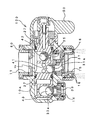
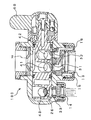
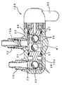
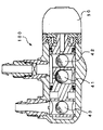
- FIG. 1 It is a perspective view which shows the state which connected the switching cock for water purifiers of this invention to the faucet of a faucet, and connected the water purifier to this switching cock for water purifiers. It is a perspective view which shows the state which is going to connect the connection hose from a water purifier to the back side of the switching cock for water purifiers. It is an enlarged longitudinal cross-sectional view of the switching cock for water purifiers at the time of normal discharge.
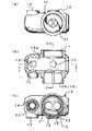
- the cock main body which comprises the switching cock for water purifiers which concerns on this invention is shown, (a) is a top view, (b) is a longitudinal cross-sectional view, (c) is a seat surface view.
- (A) is a plan view
- (b) is a right side view
- (c) is a front view
- (d) is a view from a switching rotator which constitutes the switching cock for the water purifier.
- 3 is a cross-sectional view taken along the line 3-3
- (e) is a cross-sectional view taken along the line 4-4 in (c).
- the pressure control valve which comprises the switching cock for water purifiers which concerns on this invention is shown, (a) is a perspective view of a pressure control valve, (b) is sectional drawing when pressure is not applied to the pressure control valve, (c) ) Is a cross-sectional view when a high pressure is applied to the pressure control valve.
- FIG. 1 shows a state in which the switching faucet 100 for water purifier according to the present invention is attached to the faucet 210 of the faucet 200 and used, and the switching faucet 100 for water purifier is separate from this and is in the sink , Etc. are connected via two connection hoses 310 to a water purifier 300 installed at another place such as For that purpose, as shown in FIG. 2, the raw water supply port 12 and the purified water inflow port 13 are formed so as to protrude from the back side of the cock body 10 constituting the switching faucet 100 for water purifier.
- Connection hoses 310 are respectively connected to the raw water supply port 12 and the purified water inlet 13, and the other ends of the connection hoses 310 are respectively connected to the water supply port and the water purification port of the water purifier 300 as shown in FIG. It is
- the connection of the switching cock 100 for water purifier to the faucet 210 is made by attaching the fixture 60 to the raw water port 11 formed at the upper end of the cock body 10 constituting the switching cock 100 for water purifier. It is attached and made to be able to be performed via this mounting tool 60.
- the fixture 60 corresponding to the shape of the faucet 210 is prepared, and the water purifier switching faucet 100 can be attached to any faucet 210. It has become.
- the axial center of the cylindrical storage space 10a of the cock body 10 of the switching faucet 100 for water purifier is disposed substantially horizontally.
- the switching rotary member 20 described later is housed in the storage space 10a so as to be movable, the switching rotary member 20 is also arranged so that its axis is substantially horizontal.
- the switching cock 100 for water purifier has a cock main body 10 whose external appearance is shown in FIGS. 1 and 2, a switching rotary element 20 housed and supported substantially horizontally in the cock main body 10, and the switching time
- the switching handle 50 integrated with the outer end (the right end as shown in FIG. 3 in the present embodiment) of the moving element 20 is a basic component.
- the cock body 10 is a cylindrical one having a horizontal cylindrical space for housing the switching rotary member 20, and is a raw water port connected to a faucet 210 of water supply etc. 11, the raw water supply port 12 and the purified water inlet 13 respectively connected to the water supply port and the purified water port on the side of the water purifier 300, the purified water outlet 14 located in the vicinity of the purified water inlet 13 and the vicinity of the raw water port 11 And a shower port 16 located around the normal discharge port 15.
- the raw water supply port 12 of the cock body 10 is connected to the water purifier 300 via the connection hose 310 as shown also in FIG. 1, and for example, as shown in FIG. 9 and FIG. It is always in communication with the water port 11. Therefore, there is a possibility that the raw water of abnormal pressure is supplied to the water purifier 300 side through the raw water supply port 12, or the raw water on the water purifier 300 side may reversely flow back into the cock body 10, but In the switching faucet 100 for water purifier of the embodiment, as shown in FIG. 9 or FIG. 10, such a problem is prevented from occurring by providing the metering plug 12a in the raw water supply port 12.
- the flow control fitting 15a is accommodated in the normal discharge port 15 of the cock body 10, and the normal discharge can be performed without splashing water. The same one as the straightening fitting 15a is also provided in the clean water discharge port 14.
- the switching rotator 20 rotatably housed in the cock body 10 is as shown in FIG. 5, and the normal discharge passage 21 for selectively communicating the raw water port 11 and the normal discharge port 15 with each other.
- a shower discharge passage 22 selectively connecting the raw water port 11 and the shower opening 16 and a clean water discharge passage 23 selectively communicating the clean water inlet 13 and the clean water discharge port 14 in the circumferential direction It is.
- this switching rotary member 20 is housed in a fluid tight manner in the cock main body 10 and is rotated about the axial center in the lateral direction, the right side of the shower discharge passage 22 and the normal discharge passage 21
- An annular groove is formed between the water purification discharge passage 23 and the annular ring, that is, the ring-shaped packing 27.
- the annular packing 27 makes the right side of the shower discharge passage 22, the normal discharge passage 21 and the clean water discharge passage 23 In particular, the sealing is performed with light torque in the circumferential direction.
- each of the pulling-up portions 24 to 26 needs to be configured to have a cylindrical shape when viewed from one end side as shown in (b) of FIG. The specific configuration is shown in (a), (c) and (e) of FIG.
- valve seats 31 to 33 are respectively disposed immediately above the clean water discharge port 14, the normal discharge port 15 and the shower port 16 of the cock body 10, and in the present embodiment, the switching rotary element 20 is Since it is partitioned as described above by the two packings 27, normally the valve seat 31 and the shower valve seat 32 are integrally formed, but these and the clean water valve seat 33 are separately formed is there.
- the valve holes 31a 32a and 33a of the respective valve seats 31 to 33 are circular so as to completely receive and close the respective ball valves 41 to 43.
- the water purifier switching cock 100 normally opens the discharge port 15, the shower port 16 and the clean water discharge port 14 vertically downward, and the normal discharge port 15, the shower port 16, and the clean water discharge port
- the valve seats 31, 32 and 33 are respectively provided immediately above 14, and the ball valves 41, 42 and 43 are rotatably accommodated in the respective discharge passages 21, 22 and 23 of the switching rotor 20.
- the valve body 41, 42, 43 is placed by its own weight on each valve seat 31, 32, 33, the valve port of the valve seat is pierced, and each discharge passage 21, 22 of the switching rotor 20 is made.
- the pull-up portions 24, 25 and 26 are formed to selectively pull up the corresponding ball valves 41, 42 and 43 from the respective valve seats 31 to 32.
- Each of the ball valves 41 to 43 in the present embodiment is made of synthetic rubber as a material so that at least the surface becomes soft. The reason is that the ball valves 41 to 43 are mounted on the valve seats 31 to 33 only by their own weight, and at that time, the valve holes 31a, 32a or 33a can be reliably closed. It is to do so. For the same reason, the valve seats 31 to 33 are also made of a relatively soft synthetic resin.
- the selected discharge of the normal discharge, the shower discharge, and the purified water discharge is stored in the normal discharge passage 21 on the switching rotary element 20 side, the shower discharge passage 22 and the clean water discharge passage 23 respectively.
- This is performed by the one-ball valve body 41, the second ball valve body 42, and the third ball valve body 43.
- the water discharge outlet 14 the normal discharge The outlet 15 and the shower port 16 are opened downward, and the clean water valve seat 33, the normal valve seat 31 and the shower valve seat 32 are opened horizontally, and the respective openings (valve ports) are opened.
- the one-ball valve body 41, the second ball valve body 42, and the third ball valve body 43 can be reliably closed.
- first ball valve body 41, the second ball valve body 42, and the third ball valve body 43 do not have to be closed, that is, the clean water discharge port 14, the normal discharge port 15 or the shower port
- first ball valve body 41, the second ball valve body 42 or the third ball valve body 43 from the respective clean water valve seats 33, usually the valve seat 31 or the shower valve seat 32
- the first pull-up portion 24, the second pull-up portion 25, and the third pull-up portion 26 that perform pull-up must be within the normal discharge passage 21, the shower discharge passage 22, and the clean water discharge passage 23 on the switching rotary element 20 side. It is formed in each.
- the pressure control valve 70 is housed in the raw water port 11 formed in the upper part of the cock main body 10 constituting the switching cock 100 for water purifier .
- the pressure control valve 70 is fixed to the cock body 10 by a fitting 60 screwed to the raw water port 11, and the raw water port 11 has a diameter slightly larger than the diameter of the pressure control valve 70 which is not deformed.
- a material having a diameter of about 1.8 cm and a thickness of about 3 mm is integrally formed of synthetic rubber such as silicone rubber or propylene rubber. Then, as shown in (a) to (b) of FIG. 6, the pressure control valve 70 is accommodated so as to be contractible in the direction orthogonal to the flow path in the storage portion 21 and has a wall parallel to the flow path Base portion 71, an annular plate portion 72 integrated on the secondary side of the base portion 71, and an inner end of the annular plate portion 72, the tip 13a is inclined toward the primary side of the flow path An annular inclined portion 73 and a through hole 74 formed on the tip 13 a side of the annular inclined portion 73 are provided.
- the pressure adjusting valve 70 is formed such that the tip 73 a of the annular inclined portion 73 when no force is applied is completely accommodated in the raw water port 11. is there. By doing in this way, when it bend
- the normal discharge passage 21 and the normal discharge port 15 are communicated with each other, and the communication between the shower discharge passage 22 and the shower port 16 and the clean water discharge passage 23 and the clean water discharge port 14 is the second ball valve 42
- the raw water blocked by the third ball valve 43 and supplied to the raw water port 11 side is usually discharged from the discharge port 15 through the discharge passage 21.
- the raw water port 11 normally communicates with the discharge passage 21 and the shower discharge path 22, and as shown in FIGS. 9 to 11, the raw water port 11 is connected to the raw water supply port 12. It also communicates. Therefore, the pressure of the raw water supplied from the faucet 210 of the faucet 200 is always applied to the discharge passage 21 and the shower discharge passage 22 and also to the raw water supply port 12 side. However, since the metering plug 12a is provided in the raw water supply port 12 and the clean water discharge port 14 is not opened, the raw water from the faucet 210 not only flows into the water purifier 300 but also Water does not flow back from the water purifier 300 to the water purifier switching cock 100 side.
- the clean water discharge port 14 of the switching cock 100 for the water purifier opens downward, and the valve port 33 a of the clean water valve seat 33 is the third ball valve on the clean water valve seat 33.
- the third ball in the clean water discharge passage 23 is drilled by the body 43, and a certain amount of water pressure from the faucet 210 is applied to the third ball valve body 43 through the metering plug 12a in the raw water supply port 12.
- the valve body 43 is in close contact with the clean water valve seat 33 unless it is forcibly pulled up from the clean water valve seat 33 by the third pulling-up unit 26.
- FIGS. 7 and 10 The state in which shower discharge is performed in the switching cock 100 for water purifier is shown in FIGS. 7 and 10, and in the case of the embodiment, the switching handle 50 is directed downward. Further, at this time, as shown in FIG. 7, only the second ball valve body 42 is pulled up by the second raising portion 25 and pulled away from the shower valve seat 32, and the first ball valve The body 41 is normally placed on the valve seat 31 and the third ball valve 43 is placed on the clean water valve seat 33.
- the raw water port 11 to which the faucet 210 is connected is in communication with the shower port 16 through the shower discharge passage 22, so that raw water is discharged from the shower port 16 in a shower state.
- the state in which the water purification discharge is being performed in the switching cock 100 for water purifier is shown in FIG. 8 and FIG. 11, and the switching handle 50 is pivoted so as to protrude upward as shown in FIG. .
- the first ball valve body 41 and the second ball valve body 42 normally close the valve seat 31 and the shower valve seat 32 by their own weight, and the third ball valve body 43 is formed in the purified water discharge passage 23 It is pulled up from the purified water valve seat 33 by a certain third raising portion 26, and the purified water discharge port 14 is in an open state.
- the raw water of the faucet 210 supplied from the raw water port 11 passes through the metering plug 12 a of the raw water supply port 12 and is supplied into the water purifier 300, and the raw water is collected in the water purifier 300. Purification is performed, and the water is returned to the side of the water purifier switching cock 100 through the connection hose 310. And since the purified water discharge port 14 is open
- the selective opening and closing of the clean water discharge port 14, the normal discharge port 15, and the shower port 16 is performed by the normal valve seat 31, the shower valve seat 32, and the clean water Since the first ball valve body 41, the second ball valve body 42 and the third ball valve body 43 are pulled up on the valve seat 33 and placed by their own weight, for example, the cock body 10 and the switching rotary element If compared with the opening and closing by sliding contact with 20, the seal structure can be simplified, the structure can be simplified, and the durability can be made high.
- the water purification outlet 14 is opened downward, and the water purification valve seat 33 is made horizontal, and the opening and closing of the valve opening 33 a of the water purification valve seat 33 is described above. Since the third ball valve 43 is used, it is possible to block the entry of air when the purified water is not being discharged.
Landscapes
- Engineering & Computer Science (AREA)
- General Engineering & Computer Science (AREA)
- Health & Medical Sciences (AREA)
- Life Sciences & Earth Sciences (AREA)
- Hydrology & Water Resources (AREA)
- Public Health (AREA)
- Water Supply & Treatment (AREA)
- Mechanical Engineering (AREA)
- Multiple-Way Valves (AREA)
- Domestic Plumbing Installations (AREA)
- Water Treatment By Sorption (AREA)
Abstract
【課題】通常吐出、シャワー吐出、及び浄水吐出の3種類の切換えを行うことができて、構造が簡単で雑菌混入の原因となる空気の侵入を防止することができ、さらには使用後の水切りが良くて、圧力調整をも簡単に行える切換コックを提供すること。 【解決手段】コック本体10を、原水口11と、原水供給口12及び浄水流入口13と、浄水吐出口14と、通常吐出口15と、シャワー口16とを有したものとするとともに、切換回転子20を、原水口11と通常吐出口15とを選択的に連通させる通常吐出通路21と、原水口11とシャワー口16とを選択的に連通させるシャワー吐出通路22と、浄水流入口13と浄水吐出口14とを選択的に連通させる浄水吐出通路23とをそれぞれ周方向に有したものとし、基体部71と、この基体部71に一体化された環状板部72と、この環状板部72の内端に一体化されて先端73aが流路の一次側に向けて傾斜する環状傾斜部73と、この環状傾斜部73の先端73a側に形成した通孔74とにより構成した圧力調整弁70をコック本体10の原水口11内に設けたこと。
Description
本発明は、水道の蛇口等に取り付けられて、浄水器側にも接続される浄水器用切換コックに関し、特に、浄水器からの浄水吐出と、水道水の通常吐出、及び水道水のシャワー吐出の三種類吐出が選択的に行える浄水器用切換コックに関するものである。
近年、水道水を浄化して所謂「おいしい水」を作り出す浄水器が種々提案されており、このような浄水器は、台所等において一般的に使用されるようになってきている。この種の浄水器は、内部にフィルターを入れておかなければならないものであるから、水道の蛇口に直接取付けるものは少なく、一般的には、例えば特許文献1に示されたような切換弁を使用して蛇口等に接続されるものである。
この特許文献1に示された「浄水器用切換弁」は、「供給される原水の圧力が高くなっても一定圧力の原水を浄水器本体へ供給できるとともに、摺動状態を改善して各構成部材の破壊等が生じない浄水器用切換弁を提供する」ことを目的としてなされたものである。
この特許文献1の切換弁によれば、水道から供給される原水を、浄水器本体へ供給する浄水位置(浄水吐出)と、通過させる原水位置(通常吐出)と、シャワーとして吐出させるシャワー位置(シャワー吐出)の3状態に切換えることができて、しかも上記目的を達成することができるものと考えられる。
しかしながら、この特許文献1の切換弁は、そのコックケース(5)と、これの内部に嵌合したチェンジバルブ(17)との摺接によって切換機能を発揮させるものであるから、材料の選定を厳しく行わなければならないだけでなく、コックケース(5)やチェンジバルブ(17)の製造を相当厳格に行わなくてはならない。
それだけでなく、この特許文献1の切換弁では、水道からの原水を浄水器側に単に送り込むだけのものとなっていて、浄水は当該切換弁には形成されていない別の浄水吐出から吐出させなければないらないものとなっている。この切換弁は、通常吐出とシャワー吐出が行える吐出口を有しているのであるから、これらの近傍に浄水吐出口があると便利である。
また、一般的に、水道水中にはコックや水栓の内部部品表面に付着する種々な不純物が含まれているものであり、この不純物が内部部品に付着すると、コックや水栓の構成部品間の動きが悪くなることが知られている。特に特許文献1の切換弁のような摺接面が多い構造のものであると、水道水中の不純物によって各部の動きが悪くなり、ハンドルの操作性が非常に短時間の間に悪くなることが多い。
さらに、一般的に、浄水吐出は常時行われるものではないから、浄水器にて浄化された浄水は、その吐出がなされるまでの間、配管内に貯めておかれるものである。この貯めておかれている浄水中に雑菌が混入して繁殖すると、浄水が浄水でなくなる。雑菌混入の最大の原因は、雑菌を含む空気が浄水中に混入することであり、この空気の混入は、上述したような各種切換弁においてよく起るものである。何故なら、切換弁において止水されると、水と入れ換わりに空気が入り込むからである。
さらにまた、都市ガスや水道水等の流体は、一定の圧力で供給源から配給されてくるものであり、浄水器においては、それに最適な圧力で供給するようにしなければならない。つまり、水道水等は、比較的大きな圧力で各戸毎に供給されるものであり、その供給圧力は、各戸の使用状況にも応じて変化するものであるが、浄水器等の流体使用機器では、供給圧力が大きく低下した場合であっても機能できるようにするために、その最適圧力は供給圧力よりも低目に設定されていることが多い。
このため、一般的には、水道管路中に、供給されてきた水道水の圧力を使用機器に応じたものに低下させるための圧力調整弁を有する圧力調整弁装置が使用されている。従来の圧力調整弁装置は、ピストン弁体を一体化しておくとともに、このピストンをスプリングの弾性力によって流路中を動き得るようにして、高い圧力が加わったときにはピストンを動かして、これと一体化されている弁体によって通孔を狭くして圧力の調整や流量の調整を行うようにしたものが一般的である。なお、このような圧力調整弁装置中には逆止弁を介在させることがある。
以上のような構造を有する圧力調整弁装置は、それだけで構造が複雑であり、ピストンやスプリングを収納する場所を管路中に確保しなければならない。いきおい、水道管等の管路に後付けされる別体のものとして、この圧力調整弁装置を構成しなければならず、製造も、水道管等に対する取付工事も大がかりなものとなる。
以上の従来技術の検討の結果、本発明者等は、この種の浄水器用切換コックにおいては、次の諸点を改良あるいは改善していかなければならないことを見出したのである。
(1)原水の通常吐出、シャワー吐出、及び浄水の吐出を蛇口の近傍で行えるようにすること。
(2)この種の浄水器用切換コックは、不純物を含む水道水等の原水の吐出方法の切換えを行なうのに使用されるものであるから、内部部品に不純物の付着があったとしても、操作性に影響を与えないようにできるだけ簡単な構造のものとして、切換え操作を長期間安定的に行えるようにすること。
(3)簡単な構造であっても、雑菌混入の原因となる空気がコック内に容易には入り込まないようにすること。
(4)通常吐出、シャワー吐出、及び浄水の吐出をした後に、吐出が直ちに停止すること(水切りがよいこと)。
(5)流体の圧力調整を簡単に行えるようにすること。
(1)原水の通常吐出、シャワー吐出、及び浄水の吐出を蛇口の近傍で行えるようにすること。
(2)この種の浄水器用切換コックは、不純物を含む水道水等の原水の吐出方法の切換えを行なうのに使用されるものであるから、内部部品に不純物の付着があったとしても、操作性に影響を与えないようにできるだけ簡単な構造のものとして、切換え操作を長期間安定的に行えるようにすること。
(3)簡単な構造であっても、雑菌混入の原因となる空気がコック内に容易には入り込まないようにすること。
(4)通常吐出、シャワー吐出、及び浄水の吐出をした後に、吐出が直ちに停止すること(水切りがよいこと)。
(5)流体の圧力調整を簡単に行えるようにすること。
本発明は、浄水器用切換コックにおける上記実状に鑑みてなされたもので、その解決しようとする課題は、通常吐出、シャワー吐出、及び浄水吐出の3種類の切換えを行うことができて、構造が簡単で雑菌混入の原因となる空気の侵入を防止することができ、さらには使用後の水切りが良くて、圧力調整をも簡単に行える切換コックを提供することにある。
以上の課題を解決するために、本発明の採った手段は、後述する実施形態の説明中で使用する符号を付して説明すると、
「コック本体10の収納空間10a内に切換回転子20を回動可能かつ液密状に収納して、この切換回転子20を切換ハンドル50の操作によって回転させることにより、コック本体10からの原水の通常吐出、シャワー吐出または浄水の吐出を選択的に行えるようにした浄水用切換コック100であって、
コック本体10を、水道の蛇口210等に接続される原水口11と、浄水器300側の給水口及び浄水口にそれぞれ接続される原水供給口12及び浄水流入口13と、この浄水流入口13の近傍に位置する浄水吐出口14と、原水口11の近傍に位置する通常吐出口15と、この通常吐出口15の周囲に位置するシャワー口16とを有したものとするとともに、
切換回転子20を、原水口11と通常吐出口15とを選択的に連通させる通常吐出通路21と、原水口11とシャワー口16とを選択的に連通させるシャワー吐出通路22と、浄水流入口13と浄水吐出口14とを選択的に連通させる浄水吐出通路23とをそれぞれ周方向に有したものとし、
さらに、コック本体10の原水口11内に、この原水口11の流路と直交する方向に収縮可能に収納されて、流路と平行な壁となる基体部71と、この基体部71の二次側に一体化された環状板部72と、この環状板部72の内端に一体化されて先端73aが流路の一次側に向けて傾斜する環状傾斜部73と、この環状傾斜部73の先端73a側に形成した通孔74とにより構成した圧力調整弁70を設けたことを特徴とする浄水器用切換コック100。」
である。
「コック本体10の収納空間10a内に切換回転子20を回動可能かつ液密状に収納して、この切換回転子20を切換ハンドル50の操作によって回転させることにより、コック本体10からの原水の通常吐出、シャワー吐出または浄水の吐出を選択的に行えるようにした浄水用切換コック100であって、
コック本体10を、水道の蛇口210等に接続される原水口11と、浄水器300側の給水口及び浄水口にそれぞれ接続される原水供給口12及び浄水流入口13と、この浄水流入口13の近傍に位置する浄水吐出口14と、原水口11の近傍に位置する通常吐出口15と、この通常吐出口15の周囲に位置するシャワー口16とを有したものとするとともに、
切換回転子20を、原水口11と通常吐出口15とを選択的に連通させる通常吐出通路21と、原水口11とシャワー口16とを選択的に連通させるシャワー吐出通路22と、浄水流入口13と浄水吐出口14とを選択的に連通させる浄水吐出通路23とをそれぞれ周方向に有したものとし、
さらに、コック本体10の原水口11内に、この原水口11の流路と直交する方向に収縮可能に収納されて、流路と平行な壁となる基体部71と、この基体部71の二次側に一体化された環状板部72と、この環状板部72の内端に一体化されて先端73aが流路の一次側に向けて傾斜する環状傾斜部73と、この環状傾斜部73の先端73a側に形成した通孔74とにより構成した圧力調整弁70を設けたことを特徴とする浄水器用切換コック100。」
である。
すなわち、本発明に係る浄水器用切換コック100は、図1及び図2に示すように、水栓200の蛇口210等に対して取付具60を利用して取付けるとともに、当該浄水器用切換コック100とは別体で例えば台所用シンク内に配置される浄水器300の給水口(浄水となるべき原水が供給される入口)及び浄水口(当該浄水器300内で成生された浄水を排出する出口)に、図1及び図2に示したような接続ホース310によって接続して使用されるものである。そして、この浄水器用切換コック100は、その中に水栓200を操作して蛇口210からの水道水等を送り込んだとき、当該浄水器用切換コック100の切換ハンドル50の位置によって、通常吐出、シャワー吐出または浄水吐出を、蛇口210の近傍の一箇所で選択的に行えるようにしたものなのである。
そのために、この浄水器用切換コック100では、まずそのコック本体10内に切換回動子20を回動可能に収納してあり、この切換回動子20の外端に設けた切換ハンドル50の回動の操作によって、通常吐出、シャワー吐出及び浄水吐出の選択が容易に行えるようにしてある。具体的には、コック本体10は、図4の(b)に示したように、その上端に設けた原水口11を水栓200の蛇口210(通常は下方に向けて開口している)に接続することにより、軸心が横方向になる円筒状の収納空間10aを有したものとして形成してあり、この収納空間10a内にその軸心を回動中心として回動される略円柱状の切換回動子20を横方向に収納することにより、当該浄水器用切換コック100は構成されているのである。
勿論、この浄水器用切換コック100は、切換回動子20の回動によって、通常吐出、シャワー吐出または浄水吐出の選択操作を行うものであるから、円筒状のコック本体10に、原水口11、原水供給口12、浄水流入口13、浄水吐出口14、通常吐出口15及びシャワー口16の6つの開口を形成するとともに、これらの各開口を選択的に連通させるための通常吐出通路21、シャワー吐出通路22及び浄水吐出通路23を、図5に示すように、切換回動子20側に形成してあるのである。
これらの通常吐出通路21、シャワー吐出通路22及び浄水吐出通路23による選択的連通は、次に述べる本実施形態に係る浄水器用切換コック100のように、第1球弁体41、第2球弁体42、及び、第3球弁体43を使用して行ってもよいが、コック本体10と切換回動子20との摺接によって行ってもよいものである。また、切換回動子20は、その水平方向の軸心を中心とする回動によって上記選択的連通を行わなければならないから、上記通常吐出通路21、シャワー吐出通路22及び浄水吐出通路23は、当該切換回動子20の周方向に形成しなければならないものである。
この浄水器用切換コック100は、通常吐出通路21、シャワー吐出通路22及び浄水吐出通路23による選択的連通を、第1球弁体41、第2球弁体42、及び、第3球弁体43によって行うと、図8及び図3に示すように、これらが、通常弁座31、シャワー弁座32、浄水弁座33にそれぞれ着座して弁孔を閉じるから、水切りが非常に効率的に行われて、通常吐出通路21、シャワー吐出通路22あるいは浄水吐出通路23からの水は完全に止められるのである。何故なら、通常弁座31、シャワー弁座32、及び浄水弁座33は、弁孔を中心にした皿状の座面を有していて、この座面上に、第1球弁体41、第2球弁体42、及び、第3球弁体43gさそれぞれ重力によって当接するからである。
なお、この浄水器用切換コック100においては、そのコック本体10の軸心が横方向に位置する収納空間10a内に、横方向に配置される切換回動子20を、当該切換回動子20の周方向に設けた円環状のパッキング27を介して回動可能に収納したから、コック本体10と切換回転子20との摺接は、円環状の線としての各パッキング27を中心にしてなされることになる。そして、各パッキング27が円環状のものであるとともに、これらのパッキング27の間に上記通常吐出通路21、シャワー吐出通路22及び浄水吐出通路23が切換回転子20の外周の周方向に円環状に位置しているから、浄水吐出通路23が他の通路と完全に区画されており、水道水が浄水中に混入することもない。
さて、この圧力調整弁装置100を構成する圧力調整弁70は、合成ゴム等の弾性材によって一体的に形成したものであって、例えば図3に示すように、原水口11内に収納されるものである。そして、通常状態(何等の力も加えない状態)では、図6の(a)及び(b)に示すような略円板状のものである。
この圧力調整弁70を介して原水口11内に流体(水道水)が通されれば、図6の(c)に示すように、その上流側の圧力が環状板部72及び環状傾斜部73の図示上面側にかかることになる。この水道圧力が、圧力調整弁70を構成している弾性材の弾性変形範囲を越えないものであれば、図6の(b)に示すように、環状板部72や環状傾斜部73は何等変化しない。このときの、環状傾斜部73の先端部73aによって形成された通孔74の直径をD1とすると、このD1も変化しない。
水道水の圧力がある範囲を越えると、この圧力を受けている環状傾斜部73は、図6の(c)に示すように、弾性変形をすることになりる。すなわち、文字通り傾斜状態にあった環状傾斜部73が、原水口11中を流れる水道水の圧力により押圧され、偏平に近い状態にまで変形するのである。このとき、圧力調整弁70の基体部71は外側に僅かに膨らむが、環状板部72は原水口11側に支持されているため変形しない。
以上の結果、偏平になった環状傾斜部73の先端部73aによる通孔74の直径は、図6の(c)中に示したD2となり、このD2<D1の関係となる。つまり、水道水の圧力により押し潰された環状傾斜部73によって、通孔74の直径が少し小さくなり、二次側に流れる水道水の圧力を小さくするとともに、それに応じて流水量を少なくするのである。
原水口11の二次側には、浄水器300が取付けられるのであるが、一般には浄水器300は、その中を水道水がゆるやかに流れることによってその浄水機能を十分発揮することができるものである。つまり、余り高い圧力、あるいは所定以上の量の水を供給しても、浄水器300はその浄水機能を十分に発揮しないのであるが、この圧力調整弁70を浄水器300の一次側に配置することによってそのような問題がなくなるのである。
また、この圧力調整弁70によれば、浄水器300への供給流体、例えば水道水の圧力を適宜なものに調整するのであるから、言わば余分な水道水を送り込むことがない。言わば、この圧力調整弁70は、節水対策を講じたものとなるのである。
そして、この圧力調整弁70は、図6に示すように、円環状の小さなものであるため、これを原水口11中に収納することを簡単に行えることは言うまでもなく、原水口11そのものの構造を非常にシンプルにすることができるのである。
なお、この圧力調整弁70を構成している圧力調整弁70は、環状傾斜部73を、基体部71に囲まれた範囲内のものとしたことによって、外枠を構成している円環状の基体部71から突出する部分がなく、原水口11内に対する納まりを良好にできる。
従って、本発明に係る浄水器用切換コック100においては、水道水中の不純物がパッキング27等に付着したとしても、切換回転子20の回動操作を長期間安定して行えるのであり、浄水の漏れは勿論のこと、浄水中への水道水の混入も長期間なく、さらには使用後の水切りが良くて、圧力調整をも簡単に行えるのである。
また、以上のように構成した本発明に係る浄水器用切換コック100では、通常吐出、シャワー吐出または浄水吐出の3種類の吐出を蛇口210の近傍で行うことができるのであり、原水口11等の6つの開口を有するコック本体10内に通常吐出通路21、シャワー吐出通路22及び浄水吐出通路23を有する切換回動子20を回動可能に収納して構成できるから、その全体構造を非常に簡単なものとすることができ、コンパクトなものとなっているのである。
以上、説明した通り、本発明においては、
「コック本体10の収納空間10a内に切換回転子20を回動可能かつ液密状に収納して、この切換回転子20を切換ハンドル50の操作によって回転させることにより、コック本体10からの原水の通常吐出、シャワー吐出または浄水の吐出を選択的に行えるようにした浄水用切換コック100であって、
コック本体10を、水道の蛇口210等に接続される原水口11と、浄水器300側の給水口及び浄水口にそれぞれ接続される原水供給口12及び浄水流入口13と、この浄水流入口13の近傍に位置する浄水吐出口14と、原水口11の近傍に位置する通常吐出口15と、この通常吐出口15の周囲に位置するシャワー口16とを有したものとするとともに、
切換回転子20を、原水口11と通常吐出口15とを選択的に連通させる通常吐出通路21と、原水口11とシャワー口16とを選択的に連通させるシャワー吐出通路22と、浄水流入口13と浄水吐出口14とを選択的に連通させる浄水吐出通路23とをそれぞれ周方向に有したものとし、
さらに、コック本体10の原水口11内に、この原水口11の流路と直交する方向に収縮可能に収納されて、流路と平行な壁となる基体部71と、この基体部71の二次側に一体化された環状板部72と、この環状板部72の内端に一体化されて先端73aが流路の一次側に向けて傾斜する環状傾斜部73と、この環状傾斜部73の先端73a側に形成した通孔74とにより構成した圧力調整弁70を設けたこと」
にその構成上の特徴があり、これにより、通常吐出、シャワー吐出、及び浄水吐出の3種類の切換えを行うことができて、構造が簡単で雑菌混入の原因となる空気の侵入を防止することができ、さらには使用後の水切りが良くて、圧力調整をも簡単に行える切換コック100を提供することができるのである。
「コック本体10の収納空間10a内に切換回転子20を回動可能かつ液密状に収納して、この切換回転子20を切換ハンドル50の操作によって回転させることにより、コック本体10からの原水の通常吐出、シャワー吐出または浄水の吐出を選択的に行えるようにした浄水用切換コック100であって、
コック本体10を、水道の蛇口210等に接続される原水口11と、浄水器300側の給水口及び浄水口にそれぞれ接続される原水供給口12及び浄水流入口13と、この浄水流入口13の近傍に位置する浄水吐出口14と、原水口11の近傍に位置する通常吐出口15と、この通常吐出口15の周囲に位置するシャワー口16とを有したものとするとともに、
切換回転子20を、原水口11と通常吐出口15とを選択的に連通させる通常吐出通路21と、原水口11とシャワー口16とを選択的に連通させるシャワー吐出通路22と、浄水流入口13と浄水吐出口14とを選択的に連通させる浄水吐出通路23とをそれぞれ周方向に有したものとし、
さらに、コック本体10の原水口11内に、この原水口11の流路と直交する方向に収縮可能に収納されて、流路と平行な壁となる基体部71と、この基体部71の二次側に一体化された環状板部72と、この環状板部72の内端に一体化されて先端73aが流路の一次側に向けて傾斜する環状傾斜部73と、この環状傾斜部73の先端73a側に形成した通孔74とにより構成した圧力調整弁70を設けたこと」
にその構成上の特徴があり、これにより、通常吐出、シャワー吐出、及び浄水吐出の3種類の切換えを行うことができて、構造が簡単で雑菌混入の原因となる空気の侵入を防止することができ、さらには使用後の水切りが良くて、圧力調整をも簡単に行える切換コック100を提供することができるのである。
以上のように構成した本発明を、図面に示した実施の形態である浄水器用切換コック100について説明する。
図1には、本発明に係る浄水器用切換コック100を水栓200の蛇口210に取り付けて使用する状態が示してあり、この浄水器用切換コック100には、これとは別体でしかもシンク内等の別の場所に設置される浄水器300に、2本の接続ホース310を介して接続されるものである。そのために、この浄水器用切換コック100を構成しているコック本体10の背面側には、図2に示したように、原水供給口12と浄水流入口13とが突出形成してあり、これらの原水供給口12及び浄水流入口13には接続ホース310がそれぞれ連接され、各接続ホース310の他端は、図1にも示したように、浄水器300の給水口及び浄水口にそれぞれ接続されるものである。
この浄水器用切換コック100の蛇口210に対する接続は、例えば図3に示したように、浄水器用切換コック100を構成しているコック本体10の上端に形成してある原水口11に取付具60を取付けておいて、この取付具60を介して行えるようにしてある。勿論、蛇口210の形状は様々であるため、この蛇口210の形状に応じた取付具60が用意されていて、どのような蛇口210に対しても当該浄水器用切換コック100の取付けが行えるようになっている。
このようにすることによって、当該浄水器用切換コック100のコック本体10は、その円柱状の収納空間10aの軸心が略水平状に配置されることになるのである。この収納空間10a内に、後述する切換回動子20を稼働自在に収納すれば、当該切換回動子20もその軸心が略水平状になるように配置されることになるものである。
さて、この浄水器用切換コック100は、外観が図1及び図2に示したようなコック本体10と、このコック本体10に略水平状に収納支持される切換回動子20と、この切換回動子20の外端(本実施形態では図3に示したように右端)に一体化される切換ハンドル50とを基本構成部としているものである。
コック本体10は、図4に示すように、切換回動子20を収納するための横方向の円柱状の空間を有した円筒状のものであり、水道の蛇口210等に接続される原水口11と、浄水器300側の給水口及び浄水口にそれぞれ接続される原水供給口12及び浄水流入口13と、この浄水流入口13の近傍に位置する浄水吐出口14と、原水口11の近傍に位置する通常吐出口と15、この通常吐出口15の周囲に位置するシャワー口16とを有しているものである。
コック本体10の原水供給口12は、図1にも示したように、接続ホース310を介して浄水器300に接続されるものであり、例えば、図9及び図10に示したように、原水口11に常に連通しているものである。従って、この原水供給口12を介して浄水器300側に異常圧力の原水が供給されたり、逆に浄水器300側の原水がコック本体10内に逆流したりする可能性があるが、本実施形態の浄水器用切換コック100では、図9あるいは図10に示したように、この原水供給口12内に定量栓12aを設けることにより、そのような問題が生じないようにしてある。勿論、コック本体10の通常吐出口15内には、図3に示したように、整流金具15aを収納するようにしてあり、通常吐出が水の飛散を伴わないで行えるようにしてある。この整流金具15aと同様なものが、浄水吐出口14内にも設けてある。
コック本体10内に回動可能に収納される切換回動子20は、図5に示したようなものであり、原水口11と通常吐出口15とを選択的に連通させる通常吐出通路21と、原水口11とシャワー口16とを選択的に連通させるシャワー吐出通路22と、浄水流入口13と浄水吐出口14とを選択的に連通させる浄水吐出通路23とをそれぞれ周方向に有したものである。勿論、この切換回動子20はコック本体10内に液密的に収納されて、横方向の軸心を中心に回動されるものであるから、シャワー吐出通路22の右側及び通常吐出通路21と浄水吐出通路23との間には、円環状、つまりリング状のパッキング27を収納するための円環状の凹溝が形成してある。
この切換回動子20をコック本体10内に収納したときには、図3に示したように、各円環状のパッキング27により、シャワー吐出通路22の右側及び通常吐出通路21と浄水吐出通路23との間シールが、特に周方向について軽いトルクで行える状態でなされるものである。
また、この切換回動子20は、その右端に取付けたコック本体10内にて回動されたとき、各球弁体41~43を各弁座31~33からすくい上げながら引き上げるものでもあるから、各吐出通路21~23内に引き上げ部24~26をそれぞれ形成したものである。各引き上げ部24~26は、切換回動子20を図5の(b)に示したように、一端側からみたとき円柱状のものとなるように構成する必要があるから、それに応じた形状のものとされるのであるが、その具体的形状構成は図5の(a)、(c)及び(e)に示してある。
そして、コック本体10の浄水吐出口14、通常吐出口15、及びシャワー口16の直上には、弁座31~33がそれぞれ配置してあって、本実施形態では、切換回動子20上が2本のパッキング27によって上述したように区画されているため、通常弁座31とシャワー弁座32とは一体的に形成してあるが、これらと浄水弁座33とは別体に形成してある。勿論、各弁座31~33の弁孔31a32a及び33aは、各球弁体41~43を完全に受けて閉止されるように円形のものとしてある。
換言すれば、この浄水器用切換コック100は、通常吐出口15、シャワー口16及び浄水吐出口14を鉛直下方に開口するものとするとともに、これら通常吐出口15、シャワー口16、及び浄水吐出口14の直上に弁座31・32・33をそれぞれ設け、切換回転子20の各吐出通路21・22・23内に球弁体41・42・43を転動自在に収納し、これらの各球弁体41・42・43が各弁座31・32・33上に自重によって載置され
たとき当該弁座の弁口を穿ぐようにするとともに、切換回転子20の各吐出通路21・22・23内に該当する球弁体41・42・43を各弁座31・32・33から選択的に引き上げる引き上げ部24・25・26を形成したものなのである。
たとき当該弁座の弁口を穿ぐようにするとともに、切換回転子20の各吐出通路21・22・23内に該当する球弁体41・42・43を各弁座31・32・33から選択的に引き上げる引き上げ部24・25・26を形成したものなのである。
本実施形態における各球弁体41~43は、合成ゴムを材料として、少なくとも表面が軟質なものとなるようにしてある。その理由は、これら各球弁体41~43はその自重によってのみ各弁座31~33上に載置されるものであり、そのときに各弁孔31a、32aまたは33aの閉止を確実に行えるようにするためである。同様な理由で、各弁座31~33も、比較的軟質な合成樹脂を材料として形成してある。
すなわち、この浄水器用切換コック100では、通常吐出、シャワー吐出及び浄水吐出の選択吐出を、切換回動子20側の通常吐出通路21、シャワー吐出通路22及び浄水吐出通路23内にそれぞれ収納した第1球弁体41、第2球弁体42及び第3球弁体43によって行うようにしたことである。そして、これらの第1球弁体41、第2球弁体42及び第3球弁体43による通路の遮断を、その各自重により効果的に行えるようにするため、浄水吐出口14、通常吐出口15及びシャワー口16を下方に開口させるとともに、その浄水弁座33、通常弁座31及びシャワー弁座32の各弁口を水平状態に開口させて、これら各開口(弁口)の各第1球弁体41、第2球弁体42及び第3球弁体43による閉止を確実に行えるようにしたものである。
勿論、第1球弁体41、第2球弁体42及び第3球弁体43による閉止を行わなくてもよい場合を確保するために、つまり浄水吐出口14、通常吐出口15またはシャワー口16をそれぞれ開口させる必要がある場合には、これら第1球弁体41、第2球弁体42または第3球弁体43を各浄水弁座33、通常弁座31またはシャワー弁座32から引き上げなければならないが、それを行う第1引き上げ部24、第2引き上げ部25及び第3引き上げ部26を、切換回動子20側の通常吐出通路21、シャワー吐出通路22及び浄水吐出通路23内にそれぞれ形成してあるのである。
そして、この浄水器用切換コック100を構成するコック本体10の上部に形成してある原水口11には、図3、図7及び図8に示したように、圧力調整弁70が収納してある。この圧力調整弁70は、原水口11に螺着される取付具60によってコック本体10に固定されており、原水口11は、変形していない圧力調整弁70の直径より僅かに大きい直径のものとしてある。
この圧力調整弁70の本実施形態のものでは、シリコンゴムあるいはプロピレンゴム等の合成ゴムを材料として、直径約1.8cm、厚さ約3mmのものとして一体的に形成してある。そして、この圧力調整弁70は、図6の(a)~(b)に示したように、収納部21内に流路と直交する方向に収縮可能に収納されて流路と平行な壁となる基体部71と、この基体部71の二次側に一体化された環状板部72と、この環状板部72の内端に一体化されて先端13aが流路の一次側に向けて傾斜する環状傾斜部73と、この環状傾斜部73の先端13a側に形成した通孔74とを備えたものとしてある。
また、この圧力調整弁70は、例えば図3に示したように、力が全く加えられていないときの環状傾斜部73の先端部73aが、原水口11内に完全に納まるものとして形成してある。このようにすることによって、折り曲げて原水口11内に挿入するときに、何等の支障もなく行えるのであり、交換作業が簡単に行えるものとなっている。
さて、この本実施形態に係る浄水器用切換コック100について、通常吐出、シャワー吐出または浄水吐出を行っている場合に、各部材がどのようになっているかを、図面を参照して説明すると、次の通りである。
(通常吐出を行っている場合)
この浄水器用切換コック100において、通常吐出を行っている場合は、図9に示す通りである。すなわち、切換ハンドル50を浄水器用切換コック100の正面側に回動すると、図3に示したように、通常吐出通路21内の第1球弁体41を通常弁座31から引き上げるべく第1引き上げ部24が第1球弁体41の下側に位置するとともに、第2引き上げ部25及び第3引き上げ部26が、第2球弁体42及び第3球弁体43の上方に位置することになる。これにより、通常吐出通路21と通常吐出口15とは連通されることになり、シャワー吐出通路22とシャワー口16及び浄水吐出通路23と浄水吐出口14との各連通は第2球弁体42及び第3球弁体43によって遮断され、原水口11側に供給された原水は通常吐出通路21を通って通常吐出口15から吐出されるのである。
この浄水器用切換コック100において、通常吐出を行っている場合は、図9に示す通りである。すなわち、切換ハンドル50を浄水器用切換コック100の正面側に回動すると、図3に示したように、通常吐出通路21内の第1球弁体41を通常弁座31から引き上げるべく第1引き上げ部24が第1球弁体41の下側に位置するとともに、第2引き上げ部25及び第3引き上げ部26が、第2球弁体42及び第3球弁体43の上方に位置することになる。これにより、通常吐出通路21と通常吐出口15とは連通されることになり、シャワー吐出通路22とシャワー口16及び浄水吐出通路23と浄水吐出口14との各連通は第2球弁体42及び第3球弁体43によって遮断され、原水口11側に供給された原水は通常吐出通路21を通って通常吐出口15から吐出されるのである。
この浄水器用切換コック100においては、原水口11は通常吐出通路21及びシャワー吐出通路22に常に連通しているとともに、図9から図11に示したように、原水口11は原水供給口12にも連通している。従って、水栓200の蛇口210から供給された原水の圧力は、常に通常吐出通路21及びシャワー吐出通路22に掛るとともに、原水供給口12側にもかかることになる。ところが、原水供給口12内には定量栓12aが設けてあって、かつ浄水吐出口14は開口されていないのであるから、蛇口210からの原水は浄水器300内に流れ込むことがないだけでなく、水が浄水器300から浄水器用切換コック100側に逆流することもない。
そして、この通常吐出時、及び次に述べるシャワー吐出時において重要なことは、浄水吐出口14から空気が侵入し得ないようになっていることである。すなわち、この浄水器用切換コック100の浄水吐出口14は、下方に向けて開口しているとともに、その浄水弁座33の弁口33aは、当該浄水弁座33上に乗っている第3球弁体43によって穿がれており、しかも原水供給口12内の定量栓12aを通して蛇口210からのある程度の水圧が第3球弁体43に掛けられているから、浄水吐出通路23内の第3球弁体43は、第3引き上げ部26によって強制的に浄水弁座33から引き上げられない限り、浄水弁座33に密着した状態にある。
従って、この通常吐出時において、浄水吐出通路23は勿論、接続ホース310や浄水器300内に使用していない浄水吐出口14から空気が侵入することはなく、浄水吐出通路23や接続ホース310内にある浄水中に雑菌が混入して繁殖することはないのである。つまり、浄水吐出口14を長期間開放しなくても、浄水吐出通路23や接続ホース310内の水中に雑菌が繁殖することはなく、所謂「腐る」こともないのである。
(シャワー吐出を行っている場合)
この浄水器用切換コック100において、シャワー吐出を行っている状態は、図7及び図10に示してあり、実施形態の場合、切換ハンドル50は下方に向かうようになるのである。また、この時においては、図7に示したように、第2球弁体42のみがその第2引き上げ部25によって引き上げられて、シャワー弁座32から引き離された状態にあり、第1球弁体41はその通常弁座31上に、また第3球弁体43は浄水弁座33上に載置された状態にある。
この浄水器用切換コック100において、シャワー吐出を行っている状態は、図7及び図10に示してあり、実施形態の場合、切換ハンドル50は下方に向かうようになるのである。また、この時においては、図7に示したように、第2球弁体42のみがその第2引き上げ部25によって引き上げられて、シャワー弁座32から引き離された状態にあり、第1球弁体41はその通常弁座31上に、また第3球弁体43は浄水弁座33上に載置された状態にある。
これにより、蛇口210が接続された原水口11は、シャワー吐出通路22を通してシャワー口16に連通しているため、シャワー口16からは原水がシャワー状態で吐出されることになるのである。
勿論、この場合も浄水吐出口14は第3球弁体43の存在によって開口していないのであるから、浄水の吐出が行われないことは当然として、原水供給口12から浄水器300に原水が供給されることもない。また、浄水吐出口14側から浄水吐出通路23や接続ホース310内に、雑菌繁殖の原因となる空気の侵入が遮断されていることは前述した通りである。
(浄水吐出を行っている場合)
この浄水器用切換コック100において浄水吐出を行っている状態は、図8及び図11に示してあり、切換ハンドル50は、図8に示したように、上方に突出した状態に回動されている。そして、第1球弁体41及び第2球弁体42は、その自重によって通常弁座31及びシャワー弁座32を閉じており、第3球弁体43は浄水吐出通路23内に形成してある第3引き上げ部26によってその浄水弁座33から引き上げられていて、浄水吐出口14を開放状態にしている。
この浄水器用切換コック100において浄水吐出を行っている状態は、図8及び図11に示してあり、切換ハンドル50は、図8に示したように、上方に突出した状態に回動されている。そして、第1球弁体41及び第2球弁体42は、その自重によって通常弁座31及びシャワー弁座32を閉じており、第3球弁体43は浄水吐出通路23内に形成してある第3引き上げ部26によってその浄水弁座33から引き上げられていて、浄水吐出口14を開放状態にしている。
従って、この場合には、原水口11から供給された蛇口210の原水は、原水供給口12の定量栓12aを通過して浄水器300内に供給されて、この浄水器300内にて原水の浄化がなされ、接続ホース310を通して浄水器用切換コック100側に還流される。そして、浄水吐出口14が開放されているのであるから、浄水器300からの浄水はこの浄水吐出口14から吐出されるのである。
以上のように、この本実施形態に係る浄水器用切換コック100においては、その浄水吐出口14、通常吐出口15及びシャワー口16の選択的開閉を、通常弁座31、シャワー弁座32及び浄水弁座33上に対する各第1球弁体41、第2球弁体42及び第3球弁体43の引き上げ及び自重による載置によって行うようにしているから、例えばコック本体10と切換回動子20との摺接による開閉に比較すれば、シール構造を簡略化できて構造を簡単にすることができ、かつ耐久性の高いものとすることができるのである。
また、この浄水器用切換コック100では、浄水吐出口14を下方に向けて開口させるとともに、その浄水弁座33を水平状のものとし、かつこの浄水弁座33の弁口33aの開閉を上記した第3球弁体43によって行うようにしたから、浄水吐出を行っていないときの空気の侵入を遮断することができるのである。
100 浄水器用切換コック
10 コック本体
10a 収納空間
11 原水口
12 原水供給口
12a 定量栓
13 浄水流入口
14 浄水吐出口
15 通常吐出口
15a 整流金具
16 シャワー口
20 切換回動子
21 通常吐出通路
22 シャワー吐出通路
23 浄水吐出通路
24 第1引き上げ部
25 第2引き上げ部
26 第3引き上げ部
27 パッキング
31 通常弁座
31a 弁口
32 シャワー弁座
32a 弁口
33 浄水弁座
33a 弁口
41 第1球弁体
42 第2球弁体
43 第3球弁体
50 切換ハンドル
60 取付具
70 圧力調整弁体
71 基体部
72 環状板部
73 環状傾斜部
73a 先端部
74 通孔
200 水栓
210 蛇口
300 浄水器
310 接続ホース
10 コック本体
10a 収納空間
11 原水口
12 原水供給口
12a 定量栓
13 浄水流入口
14 浄水吐出口
15 通常吐出口
15a 整流金具
16 シャワー口
20 切換回動子
21 通常吐出通路
22 シャワー吐出通路
23 浄水吐出通路
24 第1引き上げ部
25 第2引き上げ部
26 第3引き上げ部
27 パッキング
31 通常弁座
31a 弁口
32 シャワー弁座
32a 弁口
33 浄水弁座
33a 弁口
41 第1球弁体
42 第2球弁体
43 第3球弁体
50 切換ハンドル
60 取付具
70 圧力調整弁体
71 基体部
72 環状板部
73 環状傾斜部
73a 先端部
74 通孔
200 水栓
210 蛇口
300 浄水器
310 接続ホース
Claims (1)
- コック本体10の収納空間10a内に切換回転子20を回動可能かつ液密状に収納して、この切換回転子20を切換ハンドル50の操作によって回転させることにより、コック本体10からの原水の通常吐出、シャワー吐出または浄水の吐出を選択的に行えるようにした浄水用切換コック100であって、
コック本体10を、水道の蛇口210等に接続される原水口11と、浄水器300側の給水口及び浄水口にそれぞれ接続される原水供給口12及び浄水流入口13と、この浄水流入口13の近傍に位置する浄水吐出口14と、原水口11の近傍に位置する通常吐出口15と、この通常吐出口15の周囲に位置するシャワー口16とを有したものとするとともに、
切換回転子20を、原水口11と通常吐出口15とを選択的に連通させる通常吐出通路21と、原水口11とシャワー口16とを選択的に連通させるシャワー吐出通路22と、浄水流入口13と浄水吐出口14とを選択的に連通させる浄水吐出通路23とをそれぞれ周方向に有したものとし、
さらに、コック本体10の原水口11内に、この原水口11の流路と直交する方向に収縮可能に収納されて、流路と平行な壁となる基体部71と、この基体部71の二次側に一体化された環状板部72と、この環状板部72の内端に一体化されて先端73aが流路の一次側に向けて傾斜する環状傾斜部73と、この環状傾斜部73の先端73a側に形成した通孔74とにより構成した圧力調整弁70を設けたことを特徴とする浄水器用切換コック100。
Applications Claiming Priority (2)
| Application Number | Priority Date | Filing Date | Title |
|---|---|---|---|
| JP2011-087071 | 2011-04-11 | ||
| JP2011087071A JP2012219525A (ja) | 2011-04-11 | 2011-04-11 | 浄水器用切換コック |
Publications (1)
| Publication Number | Publication Date |
|---|---|
| WO2012140706A1 true WO2012140706A1 (ja) | 2012-10-18 |
Family
ID=46990533
Family Applications (1)
| Application Number | Title | Priority Date | Filing Date |
|---|---|---|---|
| PCT/JP2011/006260 Ceased WO2012140706A1 (ja) | 2011-04-11 | 2011-11-09 | 浄水器用切換コック |
Country Status (3)
| Country | Link |
|---|---|
| JP (1) | JP2012219525A (ja) |
| CN (1) | CN102734502A (ja) |
| WO (1) | WO2012140706A1 (ja) |
Families Citing this family (5)
| Publication number | Priority date | Publication date | Assignee | Title |
|---|---|---|---|---|
| CN103836251B (zh) * | 2012-11-23 | 2017-03-29 | 杜也兵 | 净水器轴压式换向阀的控制方法及手柄机构操控方法 |
| CN106195343B (zh) * | 2016-08-31 | 2018-05-15 | 福建金源泉科技发展有限公司 | 一种净水器用减压龙头分水器 |
| CN106195416B (zh) * | 2016-09-06 | 2018-04-17 | 东莞市倍益清环保科技有限公司 | 一种控水装置及含有控水装置的一体式水龙头净水器 |
| KR20180062623A (ko) * | 2016-12-01 | 2018-06-11 | 박영석 | 싱크대용분기밸브 |
| WO2026063519A1 (ja) * | 2024-09-20 | 2026-03-26 | 三菱ケミカル・クリンスイ株式会社 | パッキンおよび蛇口直結型浄水器 |
Citations (3)
| Publication number | Priority date | Publication date | Assignee | Title |
|---|---|---|---|---|
| JPH112343A (ja) * | 1997-06-16 | 1999-01-06 | Hayakawa Valve Seisakusho:Kk | 浄水器用切換コック |
| WO2004027298A1 (ja) * | 2002-09-17 | 2004-04-01 | Hayakawa Valve Production Co., Ltd. | 切換コック用の弁装置、及びこれを使用した切換コック |
| JP2004183247A (ja) * | 2002-11-29 | 2004-07-02 | Hayakawa Valve Seisakusho:Kk | 流量計付吐水装置、流量計付切替コック、流量計付フレキ吐水管、浄活水器用流量計、アンダーシンク型浄活水器用流量計付水栓及び流量計ユニット |
-
2011
- 2011-04-11 JP JP2011087071A patent/JP2012219525A/ja active Pending
- 2011-07-04 CN CN2011101883357A patent/CN102734502A/zh active Pending
- 2011-11-09 WO PCT/JP2011/006260 patent/WO2012140706A1/ja not_active Ceased
Patent Citations (3)
| Publication number | Priority date | Publication date | Assignee | Title |
|---|---|---|---|---|
| JPH112343A (ja) * | 1997-06-16 | 1999-01-06 | Hayakawa Valve Seisakusho:Kk | 浄水器用切換コック |
| WO2004027298A1 (ja) * | 2002-09-17 | 2004-04-01 | Hayakawa Valve Production Co., Ltd. | 切換コック用の弁装置、及びこれを使用した切換コック |
| JP2004183247A (ja) * | 2002-11-29 | 2004-07-02 | Hayakawa Valve Seisakusho:Kk | 流量計付吐水装置、流量計付切替コック、流量計付フレキ吐水管、浄活水器用流量計、アンダーシンク型浄活水器用流量計付水栓及び流量計ユニット |
Also Published As
| Publication number | Publication date |
|---|---|
| JP2012219525A (ja) | 2012-11-12 |
| CN102734502A (zh) | 2012-10-17 |
Similar Documents
| Publication | Publication Date | Title |
|---|---|---|
| US12392119B2 (en) | Plumbing component | |
| US5705067A (en) | Mixing faucet with water purifier | |
| US6634380B2 (en) | Ceramic disc diverter valve | |
| US7610931B2 (en) | Bypass valve with an integral flow sensor for a water treatment system | |
| WO2012140706A1 (ja) | 浄水器用切換コック | |
| US11028942B2 (en) | Fluid control valve | |
| JP2008532744A (ja) | 浄水器に備えられた流体遮断手段 | |
| CA2504328A1 (en) | Bypass valve | |
| CN101239261A (zh) | 可反流冲洗的过滤器 | |
| JP5275938B2 (ja) | 流量調整止水栓 | |
| CN204239808U (zh) | 水龙头 | |
| CN101524602A (zh) | 可反冲洗的过滤器 | |
| JP3081892B2 (ja) | 浄水器用切換コック | |
| KR101179375B1 (ko) | 감압밸브 | |
| EP2186952A2 (en) | Connection device for a tap and a method of connecting parts of a tap together | |
| KR20060115436A (ko) | 정수기용 필터카트리지 연결구조 | |
| JP2011027198A (ja) | 切換コック | |
| JPH0860712A (ja) | 分岐管ヘッダー | |
| KR20140076906A (ko) | 친환경 일체형 연결 아답터 | |
| AU2003213322B2 (en) | Stop/check valve for plumbing use | |
| JP5363040B2 (ja) | 壁内蔵型給水栓及びその取付構造 | |
| TW202430751A (zh) | 具有台下閥組件之多管線水龍頭 | |
| JP2005133451A (ja) | 分岐口付水栓 | |
| KR20160097747A (ko) | 선택적 사용이 가능한 수도용 티형 가압 개방식 밸브 장치 | |
| JP2003056020A (ja) | 浄水器接続用分岐止水栓 |
Legal Events
| Date | Code | Title | Description |
|---|---|---|---|
| 121 | Ep: the epo has been informed by wipo that ep was designated in this application |
Ref document number: 11863300 Country of ref document: EP Kind code of ref document: A1 |
|
| NENP | Non-entry into the national phase |
Ref country code: DE |
|
| 122 | Ep: pct application non-entry in european phase |
Ref document number: 11863300 Country of ref document: EP Kind code of ref document: A1 |