WO2012140789A1 - キャンドモータポンプ - Google Patents
キャンドモータポンプ Download PDFInfo
- Publication number
- WO2012140789A1 WO2012140789A1 PCT/JP2011/064264 JP2011064264W WO2012140789A1 WO 2012140789 A1 WO2012140789 A1 WO 2012140789A1 JP 2011064264 W JP2011064264 W JP 2011064264W WO 2012140789 A1 WO2012140789 A1 WO 2012140789A1
- Authority
- WO
- WIPO (PCT)
- Prior art keywords
- stator
- resin
- canned motor
- motor pump
- chamber
- Prior art date
- Legal status (The legal status is an assumption and is not a legal conclusion. Google has not performed a legal analysis and makes no representation as to the accuracy of the status listed.)
- Ceased
Links
Images
Classifications
-
- F—MECHANICAL ENGINEERING; LIGHTING; HEATING; WEAPONS; BLASTING
- F04—POSITIVE - DISPLACEMENT MACHINES FOR LIQUIDS; PUMPS FOR LIQUIDS OR ELASTIC FLUIDS
- F04D—NON-POSITIVE-DISPLACEMENT PUMPS
- F04D13/00—Pumping installations or systems
- F04D13/02—Units comprising pumps and their driving means
- F04D13/06—Units comprising pumps and their driving means the pump being electrically driven
- F04D13/0606—Canned motor pumps
- F04D13/0626—Details of the can
-
- F—MECHANICAL ENGINEERING; LIGHTING; HEATING; WEAPONS; BLASTING
- F04—POSITIVE - DISPLACEMENT MACHINES FOR LIQUIDS; PUMPS FOR LIQUIDS OR ELASTIC FLUIDS
- F04B—POSITIVE-DISPLACEMENT MACHINES FOR LIQUIDS; PUMPS
- F04B17/00—Pumps characterised by combination with, or adaptation to, specific driving engines or motors
-
- F—MECHANICAL ENGINEERING; LIGHTING; HEATING; WEAPONS; BLASTING
- F04—POSITIVE - DISPLACEMENT MACHINES FOR LIQUIDS; PUMPS FOR LIQUIDS OR ELASTIC FLUIDS
- F04D—NON-POSITIVE-DISPLACEMENT PUMPS
- F04D13/00—Pumping installations or systems
- F04D13/02—Units comprising pumps and their driving means
- F04D13/06—Units comprising pumps and their driving means the pump being electrically driven
- F04D13/0606—Canned motor pumps
-
- F—MECHANICAL ENGINEERING; LIGHTING; HEATING; WEAPONS; BLASTING
- F04—POSITIVE - DISPLACEMENT MACHINES FOR LIQUIDS; PUMPS FOR LIQUIDS OR ELASTIC FLUIDS
- F04D—NON-POSITIVE-DISPLACEMENT PUMPS
- F04D13/00—Pumping installations or systems
- F04D13/02—Units comprising pumps and their driving means
- F04D13/06—Units comprising pumps and their driving means the pump being electrically driven
- F04D13/0606—Canned motor pumps
- F04D13/064—Details of the magnetic circuit
-
- F—MECHANICAL ENGINEERING; LIGHTING; HEATING; WEAPONS; BLASTING
- F04—POSITIVE - DISPLACEMENT MACHINES FOR LIQUIDS; PUMPS FOR LIQUIDS OR ELASTIC FLUIDS
- F04D—NON-POSITIVE-DISPLACEMENT PUMPS
- F04D29/00—Details, component parts, or accessories
- F04D29/58—Cooling; Heating; Diminishing heat transfer
- F04D29/5806—Cooling the drive system
-
- F—MECHANICAL ENGINEERING; LIGHTING; HEATING; WEAPONS; BLASTING
- F04—POSITIVE - DISPLACEMENT MACHINES FOR LIQUIDS; PUMPS FOR LIQUIDS OR ELASTIC FLUIDS
- F04D—NON-POSITIVE-DISPLACEMENT PUMPS
- F04D29/00—Details, component parts, or accessories
- F04D29/58—Cooling; Heating; Diminishing heat transfer
- F04D29/586—Cooling; Heating; Diminishing heat transfer specially adapted for liquid pumps
- F04D29/588—Cooling; Heating; Diminishing heat transfer specially adapted for liquid pumps cooling or heating the machine
-
- H—ELECTRICITY
- H02—GENERATION; CONVERSION OR DISTRIBUTION OF ELECTRIC POWER
- H02K—DYNAMO-ELECTRIC MACHINES
- H02K3/00—Details of windings
- H02K3/30—Windings characterised by the insulating material
-
- H—ELECTRICITY
- H02—GENERATION; CONVERSION OR DISTRIBUTION OF ELECTRIC POWER
- H02K—DYNAMO-ELECTRIC MACHINES
- H02K5/00—Casings; Enclosures; Supports
- H02K5/04—Casings or enclosures characterised by the shape, form or construction thereof
- H02K5/12—Casings or enclosures characterised by the shape, form or construction thereof specially adapted for operating in liquid or gas
- H02K5/128—Casings or enclosures characterised by the shape, form or construction thereof specially adapted for operating in liquid or gas using air-gap sleeves or air-gap discs
-
- H—ELECTRICITY
- H02—GENERATION; CONVERSION OR DISTRIBUTION OF ELECTRIC POWER
- H02K—DYNAMO-ELECTRIC MACHINES
- H02K5/00—Casings; Enclosures; Supports
- H02K5/04—Casings or enclosures characterised by the shape, form or construction thereof
- H02K5/12—Casings or enclosures characterised by the shape, form or construction thereof specially adapted for operating in liquid or gas
- H02K5/128—Casings or enclosures characterised by the shape, form or construction thereof specially adapted for operating in liquid or gas using air-gap sleeves or air-gap discs
- H02K5/1285—Casings or enclosures characterised by the shape, form or construction thereof specially adapted for operating in liquid or gas using air-gap sleeves or air-gap discs of the submersible type
-
- H—ELECTRICITY
- H02—GENERATION; CONVERSION OR DISTRIBUTION OF ELECTRIC POWER
- H02K—DYNAMO-ELECTRIC MACHINES
- H02K5/00—Casings; Enclosures; Supports
- H02K5/04—Casings or enclosures characterised by the shape, form or construction thereof
- H02K5/15—Mounting arrangements for bearing-shields or end plates
-
- H—ELECTRICITY
- H02—GENERATION; CONVERSION OR DISTRIBUTION OF ELECTRIC POWER
- H02K—DYNAMO-ELECTRIC MACHINES
- H02K5/00—Casings; Enclosures; Supports
- H02K5/04—Casings or enclosures characterised by the shape, form or construction thereof
- H02K5/16—Means for supporting bearings, e.g. insulating supports or means for fitting bearings in the bearing-shields
- H02K5/167—Means for supporting bearings, e.g. insulating supports or means for fitting bearings in the bearing-shields using sliding-contact or spherical cap bearings
- H02K5/1672—Means for supporting bearings, e.g. insulating supports or means for fitting bearings in the bearing-shields using sliding-contact or spherical cap bearings radially supporting the rotary shaft at both ends of the rotor
-
- H—ELECTRICITY
- H02—GENERATION; CONVERSION OR DISTRIBUTION OF ELECTRIC POWER
- H02K—DYNAMO-ELECTRIC MACHINES
- H02K9/00—Arrangements for cooling or ventilating
- H02K9/22—Arrangements for cooling or ventilating by solid heat conducting material embedded in, or arranged in contact with, the stator or rotor, e.g. heat bridges
- H02K9/223—Heat bridges
-
- F—MECHANICAL ENGINEERING; LIGHTING; HEATING; WEAPONS; BLASTING
- F04—POSITIVE - DISPLACEMENT MACHINES FOR LIQUIDS; PUMPS FOR LIQUIDS OR ELASTIC FLUIDS
- F04B—POSITIVE-DISPLACEMENT MACHINES FOR LIQUIDS; PUMPS
- F04B17/00—Pumps characterised by combination with, or adaptation to, specific driving engines or motors
- F04B17/03—Pumps characterised by combination with, or adaptation to, specific driving engines or motors driven by electric motors
-
- F—MECHANICAL ENGINEERING; LIGHTING; HEATING; WEAPONS; BLASTING
- F05—INDEXING SCHEMES RELATING TO ENGINES OR PUMPS IN VARIOUS SUBCLASSES OF CLASSES F01-F04
- F05D—INDEXING SCHEME FOR ASPECTS RELATING TO NON-POSITIVE-DISPLACEMENT MACHINES OR ENGINES, GAS-TURBINES OR JET-PROPULSION PLANTS
- F05D2300/00—Materials; Properties thereof
- F05D2300/60—Properties or characteristics given to material by treatment or manufacturing
- F05D2300/61—Syntactic materials, i.e. hollow spheres embedded in a matrix
-
- H—ELECTRICITY
- H02—GENERATION; CONVERSION OR DISTRIBUTION OF ELECTRIC POWER
- H02K—DYNAMO-ELECTRIC MACHINES
- H02K5/00—Casings; Enclosures; Supports
- H02K5/04—Casings or enclosures characterised by the shape, form or construction thereof
- H02K5/08—Insulating casings
Definitions
- the present invention relates to a canned motor pump, and more particularly to its structure.
- the canned motor pump is a device in which a turbo pump such as a centrifugal pump and an electric motor (hereinafter simply referred to as a motor) that drives the turbo pump are integrated.
- the rotor of the motor is housed in a cylindrical stator can, and the stator of the motor is arranged outside the stator can so as to surround the rotor.
- the rotating parts of the motor including the rotor are all housed in the stator can, and the pump handling liquid enters the stator can. Since the rotating part is housed in the stator can, a structure such as a packing for sliding with the rotating part and preventing leakage of the handling liquid becomes unnecessary.
- the stator of the motor is housed in a stator chamber formed by a housing that surrounds the outer periphery of the motor and a stator can.
- the stator chamber is a sealed space to satisfy explosion-proof standards.
- Patent Document 1 discloses a canned motor in which a stator chamber is filled with resin.
- An object of the present invention is to improve the adhesion between the filler filled in the stator chamber, the stator can and the housing forming the stator and the stator chamber, and more efficiently dissipate heat.
- a resin containing spherical inorganic material particles as a filler is filled in a stator chamber in which the stator is accommodated, and the resin is cured to fix the spherical inorganic material particles to each other.
- the spherical inorganic material particles may be any spherical particles that have a small volume change even with a temperature change when the resin is cured and have a certain mechanical strength, such as alumina (aluminum oxide), zirconia (zirconia dioxide), silicon carbide.
- Spherical particle sintered body of simple substance or mixture of materials generally called ceramic, such as silicon nitride, and spherical particle sintered body of simple substance or mixture of mainly metal oxide such as silicon dioxide and magnesium oxide Sintered spherical particles of natural minerals or mixtures of natural minerals such as zircon and quartz, and spherical sintered particles or glass beads of ceramics and metal oxides or minerals.
- grains comprised by are preferable.
- the resin to be injected and cured can be selected from the liquid feeding temperature of the canned motor pump, the use environment temperature, etc., and can be a silicone resin or an epoxy resin.
- the filler since spherical inorganic material particles having a small thermal expansion are used as the filler, there is almost no change in volume and shape due to a temperature change when the resin is cured. Therefore, the spherical inorganic material particles are filled in the stator chamber in a state of being in close contact with the stator can, the housing, etc. without gaps, and the filler is a mixture of the spherical inorganic material particles and the resin even after filling and curing the resin. In addition, the adhesiveness of the filler is improved without generating an extra space between the stator can and the housing forming the stator and the stator chamber, and as a result, the heat dissipation is improved.
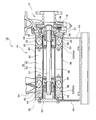
- FIG. 1 is a cross-sectional view showing a schematic configuration of the canned motor pump 10.
- the canned motor pump 10 includes a pump unit 12 having a centrifugal pump configuration and a motor unit 14 for driving the centrifugal pump.
- the pump unit 12 is not limited to a centrifugal pump, and may be configured as a turbo pump such as a mixed flow pump or an axial flow pump.
- the impeller 16 is housed in the casing chamber of the casing 18 and is coupled to the end of the motor shaft 20.
- a connecting plate 22 is fixedly coupled to the casing 18 on the rear surface side of the impeller by bolts.
- the motor unit 14 includes a motor 24 including a rotor 24 coupled so as to be integrated with the motor shaft 20 and a stator 26 arranged so as to surround the rotor 24.
- the stator 26 includes a stator core 30 having magnetic poles arranged in a circumferential direction on a substantially cylindrical inner peripheral surface, and a coil 32 formed by winding a conductive wire around the magnetic poles of the stator core. The end of the conducting wire of the coil 32 extends to the terminal box 34 and is connected to a terminal (not shown) provided in the terminal box.
- An axial groove 36 extending along the axial direction of at least one motor is provided on the outer peripheral surface of the stator core 30.
- a cylindrical stator can 38 is disposed inside the stator core 30 and outside the rotor 24.
- the stator can 38 is in contact with the inner peripheral surface of the stator core 30, that is, the tip end surface of the magnetic pole, and is disposed with a certain distance from the outer peripheral surface of the rotor 24.
- Backup sleeves 40 and 42 are provided in close contact with the outer peripheral surface of the stator can 38 at a portion of the stator can 38 that extends outward from the stator core 30 in the axial direction.
- the backup sleeves 40 and 42 have a cylindrical shape and are thicker than the stator can 38 to prevent the stator can 38 from being deformed.
- a cylindrical stator band 44 is provided along the outer peripheral surface of the stator core 30.
- the stator can 38 and the stator band 44 are doubly and concentrically arranged, and their axial lengths are substantially equal. At both ends of the stator can 38 and the stator band 44, annular end plates 46 and 48 having a circular plate shape are arranged to block the end of the cylindrical space between the stator can 38 and the stator band 44.
- the annular end plate 46 on the pump unit 12 side is coupled to the connecting plate 22 by a bolt.
- a circular plate end plate 50 that closes the end of the space inside the stator can 38 is coupled to the annular end plate 48 on the opposite side of the pump unit 12 by a bolt.
- the stator band 44, the two annular end plates 46, 48, and the disc end plate 50 can be viewed as a motor housing that houses the motor 28.
- the stator 26 is contained in a space surrounded or formed by a motor housing, in particular, a stator band 44, two annular end plates 46 and 48, and a stator can 38.
- This space is hereinafter referred to as a stator chamber 52.
- the stator chamber 52 is divided by the stator core 30 into two parts: a stator chamber 52a on the motor side and a stator chamber 52b on the opposite side.
- the divided stator chambers 52a and 52b are connected via the portion between the magnetic poles of the stator core 30 and the aforementioned axial groove 36.
- the both ends of the motor shaft 20 integrated with the rotor 24 are supported by bearings 54 and 56.
- the bearing 54 on the pump unit 12 side is held by a bearing housing 58 extending from the casing 18 of the pump unit 12.
- the bearing 56 at the opposite end is held by a bearing housing 60 extending from the disk end plate 50.
- the liquid inside the pump portion 12 sucks and discharges enters the space inside the cylindrical stator can 38, that is, the rotor chamber 62 in which the rotor 24 is accommodated.
- the handling liquid enters the rotor chamber 62 from the back side of the impeller 16, passes through the bearing 54 or the periphery thereof, passes through the gap between the rotor 24 and the stator can 38, and reaches the space opposite to the pump unit 12. From there, it passes through a center hole (not shown) penetrating along the axis to the center of the motor shaft 20 and returned to the suction side of the impeller 16.
- the canned motor pump 10 is supported entirely by legs 64 fixed to the annular end plates 46 and 48.
- the stator chamber 52 is filled with a filler 66 and hardened.
- a coil end 68 that is a portion of the coil 32 that protrudes from the stator core 30 is also embedded in the filler 66.
- the filler 66 is a mixed material of spherical inorganic material particles and a resin, particularly a silicone resin.
- spherical inorganic material particles for example, Naigai Cera Beads 60 (registered trademark) manufactured by ITOCHU CERATECH CORPORATION can be used.
- the particles are not spherical, but are round as a whole and have no corners.
- the main components are aluminum oxide (Al2O3) and silicon dioxide (SiO2).
- As the resin a component used as a binder can be used.
- the resin when the temperature of the liquid to be fed is high, the resin is preferably excellent in heat resistance.
- a silicone resin KR-242R made of Shin-Etsu silicone can be used.
- an epoxy resin can be used instead of the silicone resin depending on the environmental conditions in use, such as temperature and humidity.
- the filler 66 is filled with spherical inorganic material particles in a dry state, for example, from the terminal box 34 into the stator chamber 52.
- spherical inorganic material particles When spherical inorganic material particles are poured from the terminal box 34, the spherical inorganic material particles first flow into the stator chamber 52 b adjacent to the terminal box 34, and then pass through the portion between the magnetic poles of the stator core 30 and the axial groove 36.
- the stator chamber 52a on the side is reached.
- the stator chamber (stator chamber 52a) on the side far from the inlet side (terminal box 34) is lowered.
- the packing density can be increased by applying vibration.
- the silicone resin is filled.
- An opening for sucking up resin is provided in the lower part of the stator chamber 52, for example, the annular end plate 46, and the spherical inorganic material is formed by vacuuming the stator chamber 52 from the terminal box 34, for example, from the opposite side of the opening. Suction is performed so that the resin enters between the particles.
- the resin may be diluted with an appropriate solvent to reduce the viscosity.
- the resin is cured by heating and drying.
- spherical inorganic material particles By using spherical inorganic material particles, it can be injected into the stator chamber separately from the resin, filling work can be performed without using a large-scale facility such as injection molding, and manufacturing effort is not required.
- the corners When particles with an irregular shape are used as the filler, the corners may be crushed or broken, and the particles that are hooked at the corners may be displaced from each other, reducing the volume when the resin is cured. There is. However, since the particles of this embodiment are spherical, there is almost no volume reduction due to the close contact between the particles and a reduction in the gap between the particles. Accordingly, the adhesiveness between the hardened filler 66 and the surrounding members, for example, the stator can 38, the stator band 44, the backup sleeves 40 and 42, the stator core 30, and the coil 32 is maintained, and a space that hinders heat transfer is not created. Therefore, heat dissipation is ensured. Further, the resin enters between the magnetic pole tip of the stator core 30 and the stator can 38, and the heat transfer between them is also improved.
- the spherical inorganic material particles contact the coil 32 when the particles are poured into the stator chamber 52 and after curing, but at this time, since there are no corners as in the case of the amorphous particles, an insulating coating of the coil conductor is formed. It will not hurt.
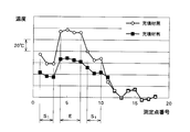
- FIG. 2 is a diagram showing the temperature of each part of the canned motor pump.
- a white circle “ ⁇ ” indicates that no filler is used, and a black square “ ⁇ ” indicates that a filler is used.
- the horizontal axis indicates the measurement points, and the measurement points in the range of S1 and S2 shown in the drawing indicate the temperature between the magnetic poles of the stator, that is, the coil surface in the slot.
- the measurement point in the range indicated by E indicates the temperature of the coil end surface.
- the used canned motor pump is a pump with an output of 30 kW, and shows the temperature at which the saturated state is reached at 100% load.
- the filler used is a combination of spherical ceramic particles and silicone resin.
- Naigai Cera Beads 60 (registered trademark) # 400 made by ITOCHU CERATECH and silicone resin KR-242R made by Shin-Etsu Silicone.
- the particle size of this model number is distributed between 150 and 425 ⁇ m.
- the thermal conductivity of Niiga Sera Bead 60 (registered trademark) is 0.56 (W / m ⁇ K)
- the thermal conductivity of silicone resin is 0.14 to 0.31 (W / m ⁇ K)
- the thermal conductivity of the filler was 0.68 (W / m ⁇ K).
- a temperature reduction effect of about 50 ° C. was recognized at the coil end portion where the temperature of the coil decreased as a whole, and the temperature increased in particular.
- Glass beads and epoxy resin can also be used as the filler.
- the glass beads for example, general purpose glass beads GB301S manufactured by Potters Barotini can be used.
- the thermal conductivity of the glass beads is 0.94 (W / m ⁇ K)
- the thermal conductivity of the epoxy resin is 0.2 (W / m ⁇ K)
- the thermal conductivity of the filler mixed with these is It was 0.44 (W / m ⁇ K).
- the filler combining glass beads and epoxy resin can be filled in the same manner as the filler combining spherical ceramic particles and silicone resin.
- the thermal conductivity of the filler of glass beads and epoxy resin is lower than that of the filler of spherical ceramic particles and silicone resin, but it was confirmed that it contributes to the heat dissipation of the coil end portion. .
- the selection of the filler it can be appropriately selected depending on the temperature of the fluid handled by the pump.
- An example of a desirable aspect of the canned motor pump of the present invention is: A turbo pump and a motor for driving the turbo pump; A cylindrical stator can placed inside the stator of the motor, containing the rotor of the motor and filled with the handling fluid of the turbo pump; A cylindrical stator band surrounding the stator outer periphery; End plates closing both ends of the cylinders of the stator can and the stator band; To form (define, define) a stator chamber that houses the stator, The stator chamber is filled with spherical inorganic material particles, and further, a fixed resin for fixing the filled spherical inorganic material particles is injected, It is a canned motor pump.
- stator 10 canned motor pump, 12 pump section, 14 motor section, 24 rotor, 26 stator, 28 motor, 30 stator core, 32 coils, 38 stator can, 44 stator band, 46, 48 annular end plate, 52 stator chamber, 66 Filler, 68 coil end.
Landscapes
- Engineering & Computer Science (AREA)
- Power Engineering (AREA)
- Mechanical Engineering (AREA)
- General Engineering & Computer Science (AREA)
- Physics & Mathematics (AREA)
- Thermal Sciences (AREA)
- Structures Of Non-Positive Displacement Pumps (AREA)
- Iron Core Of Rotating Electric Machines (AREA)
Abstract
キャンドモータポンプにおいて、モータのステータ(26)は、モータのロータ(24)を収める筒状のステータキャン(38)と、ステータキャン(38)と同軸に配置される筒状のステータバンド(44)との間の空間であるステータ室(52)内に収められる。ステータキャン(38)とステータバンド(44)の円筒端において、ステータ室(52)は、円環端部板(46),(48)により閉じられている。ステータ室(52)は、充填材(66)で満たされている。充填材(66)は、ステータ室内に充填された球状無機材料粒子と、この粒子同士を固着させる樹脂からなる。これによって、キャンドモータポンプのステータの放熱性を改善する。
Description
本発明は、キャンドモータポンプに関し、特にその構造に関する。
キャンドモータポンプは、遠心ポンプ等のターボポンプと、これを駆動する電気モータ(以下、単にモータと記す。)が一体となった装置である。モータのロータは、円筒形状のステータキャン内に収められ、モータのステータは、このステータキャンの外側に、ロータを囲むようにして配置される。ロータを含めたモータの回転部分は、すべてステータキャン内に収められ、またステータキャン内には、ポンプの取扱い液が進入している。回転部分がステータキャン内に収められていることにより、回転部分と摺動し、かつ取扱い液の漏出を防止するためのパッキン等の構成が不要となる。モータのステータは、その外周側を囲むハウジングとステータキャンとにより形成されたステータ室内に収められている。ステータ室は、防爆基準等を満たすべく密閉された空間である。特許文献1には、ステータ室内を樹脂で満たしたキャンドモータが示されている。
キャンドモータポンプにおいて、密閉されたステータ室内に配置されるステータの発した熱の放熱が問題となる。ステータ室内の空間を占める空気は熱伝導性が低いため、放熱の効率をよくするために空気より空気熱伝導性の高い樹脂等をステータ室内に充填する技術が知られている。充填された樹脂により、ステータ、特にコイルのコイルエンドで発生した熱が樹脂を介して外部に効率よく放熱される。しかし、ステータ室内に充填した樹脂を硬化させるとき、硬化過程で樹脂は一旦膨張し、その後に収縮して固化する特性があり、ステータ、ステータキャンおよびハウジングと、硬化した樹脂との間に樹脂が充填しきれない空間ができ、熱伝導性の改善が不十分という問題があった。
本発明は、ステータ室内に充填される充填材と、ステータおよびステータ室を形成するステータキャン、ハウジング等の密着性を改善し、放熱をより効率よく行うことを目的とする。
本発明のキャンドモータポンプは、ステータを収めるステータ室内に、球状無機材料粒子をフィラーとした樹脂を充填し、樹脂を硬化させ球状無機材料粒子同士を固着させている。球状無機材料粒子としては、樹脂が硬化するときの温度変化でも体積変化が少なく、ある程度の機械的強度を持つ球状なものであればよく、アルミナ(酸化アルミニウム)、ジルコニア(二酸化ジルコニア)、炭化珪素、窒化珪素などの一般的にセラミックと総称される物質の単体または混合物の球形粒子状の焼結体、二酸化珪素、酸化マグネシウムなど主に金属酸化物の単体または混合物の球形粒子状の焼結体、ジルコン、石英などの天然鉱物単体または混合物の球形粒子の焼結体、及びセラミックと金属酸化物または鉱物の混合物の球形粒子状の焼結体またはガラスビーズなどが利用でき、特に主成分がセラミックで構成されている粒子が好ましい。また、注入、硬化される樹脂はキャンドモータポンプの送液温度、使用環境温度などから選定し、シリコーン樹脂またはエポキシ樹脂とすることができる。
本発明では、熱膨張が少ない球状無機材料粒子を充填フィラーとして利用しているため、樹脂が硬化する時の温度変化による体積・形状の変化が殆どない。 このため、球状無機材料粒子がステータ室内にステータキャン、ハウジング等に密着した状態で隙間なく充填され、その後に樹脂を充填し、硬化させても、球状無機材料粒子と樹脂の混合物である充填材と、ステータおよびステータ室を形成するステータキャン、ハウジング等の間に余分な空間が発生せずに前記充填材の密着性が改善され、その結果、放熱性が改善される。
以下、本発明の実施形態を、図面に従って説明する。図1は、キャンドモータポンプ10の概略構成を示す断面図である。キャンドモータポンプ10は、遠心ポンプの構成を有するポンプ部12と、遠心ポンプを駆動するモータ部14を含む。ポンプ部12は、遠心ポンプに限らず、斜流ポンプや軸流ポンプ等のターボポンプとして構成されてもよい。ポンプ部12において、インペラ16は、ケーシング18のケーシング室内に収められ、モータ軸20の端に結合されている。ケーシング18の、インペラ後面側には、連結板22がボルトにより固定的に結合されている。
モータ部14は、モータ軸20と一体となるよう結合されるロータ24と、ロータ24の周囲を取り巻くように配置されるステータ26からなるモータ28を備える。ステータ26は、略円筒形の内周面に周方向に配列された磁極を有するステータコア30と、導線がステータコアの磁極に巻回されて形成されたコイル32を含む。コイル32の導線の端は、端子箱34に延びて、端子箱内に備えられる端子(不図示)に接続される。ステータコア30の外周面には、少なくとも1本のモータの軸線方向に沿って延びる軸線方向溝36が設けられている。
ステータコア30の内側、かつロータ24の外側には、円筒形状のステータキャン38が配置されている。ステータキャン38は、ステータコア30の内周面、すなわち磁極の先端面に接触し、一方、ロータ24の外周面との間では、一定の間隔を設けて配置されている。ステータキャン38のステータコア30から軸線方向に外に延びた部分には、ステータキャン38の外周面に密着してバックアップスリーブ40,42が設けられている。バックアップスリーブ40,42は、円筒形状であり、その肉厚はステータキャン38より厚く、ステータキャン38の変形を防止している。ステータコア30の外周面に沿って円筒形状のステータバンド44が設けられている。ステータキャン38とステータバンド44は、2重に、同心に配置され、軸線方向の長さもほぼ等しい。ステータキャン38とステータバンド44の両端には、円環板形状の円環端部板46,48が配置され、ステータキャン38とステータバンド44の間の円筒形の空間の端を塞いでいる。ポンプ部12側の円環端部板46は、連結板22とボルトにより結合されている。また、ポンプ部12と反対側の円環端部板48には、ステータキャン38の内側の空間の端を塞ぐ円板端部板50がボルトにより結合されている。ステータバンド44、二つの円環端部板46,48、および円板端部板50は、モータ28を収容するモータハウジングと見ることができる。ステータ26は、モータハウジング、特にステータバンド44および二つの円環端部板46,48と、ステータキャン38とで囲まれた、または形成された空間内に収められている。この空間を以降、ステータ室52と記す。ステータ室52は、ステータコア30により、モータ側のステータ室52aと反対側のステータ室52bの二つに分けられている。これらの分けられたステータ室52a,52bは、ステータコア30の磁極の間の部分および前述の軸線方向溝36を介して繋がっている。
ロータ24と一体のモータ軸20は、その両端を軸受54,56により支持されている。ポンプ部12側の軸受54は、ポンプ部12のケーシング18から延びる軸受ハウジング58に保持されている。一方、反対側の端の軸受56は、円板端部板50から延びる軸受ハウジング60に保持されている。円筒のステータキャン38の内側の空間、すなわちロータ24が収められるロータ室62には、ポンプ部12が吸込み、吐出する取扱い液が進入している。取扱い液はインペラ16の背面側からロータ室62に進入し、軸受54またはその周囲を通過し、さらにロータ24とステータキャン38の隙間を通過して、ポンプ部12と反対側の空間に達する。そして、そこからモータ軸20の中心に軸線に沿って貫通する中心孔(不図示)を通って、インペラ16の吸込み側に戻される。
キャンドモータポンプ10は、円環端部板46,48に固定される脚部64により、全体を支持されている。
ステータ室52には、充填材66が充填され、硬化されている。コイル32のステータコア30から出た部分であるコイルエンド68も充填材66内に埋まっている。充填材66は、球状無機材料粒子と、樹脂、特にシリコーン樹脂との混合材料である。球状無機材料粒子は、例えば伊藤忠セラテック社製ナイガイセラビーズ60(登録商標)を用いることができる。粒子は、真球状ではないが、全体として丸く、角のない粒子である。主成分は、酸化アルミニウム(Al2O3)と二酸化ケイ素(SiO2)である。樹脂は、バインダーとして用いられている成分のものが利用できる。また、送液する液の温度が高い場合などは、樹脂は耐熱性に優れたものが望ましく、例えば信越シリコーン製のシリコーン樹脂KR-242Rを使用することができる。また、使用状態の環境条件、例えば温度、湿度などによりシリコーン樹脂に替えてエポキシ樹脂を使用することもできる。
充填材66の充填は、まず、乾燥した状態の球状無機材料粒子をステータ室52内に、例えば端子箱34から流し込む。端子箱34から球状無機材料粒子を流し込んだ場合、球状無機材料粒子は、まず端子箱34に隣接するステータ室52bに流れ、次にステータコア30の磁極の間の部分および軸線方向溝36を伝い反対側のステータ室52aに達する。このとき、必要であれば、入口側(端子箱34)から遠い側のステータ室(ステータ室52a)を低くする。また、振動を加えることにより、充填密度を高めるようにすることもできる。球状無機材料粒子は、粒子が丸いために、流動性が良好であり、更に粒子径が小さいためにステータ室内の隅々までに密に充填することができる。球状無機材料粒子を充填後、シリコーン樹脂を充填する。ステータ室52の下部、例えば円環端部板46に樹脂を吸い上げるための開口を設けておき、この開口とは反対側から、例えば端子箱34からステータ室52を真空引きなどで、球状無機材料粒子間に樹脂が進入するように吸引する。このときの樹脂の流動性を高めるために、樹脂を適切な溶剤で薄め、粘度を下げるようにしてもよい。その後、加熱乾燥して、樹脂を硬化させる。球状無機材料粒子を使うことで、樹脂と別々にステータ室に注入することができ、射出成形などの大規模な設備を使用することなく、充填作業ができ、製造の手間が掛からない。
充填フィラーとして、形状が不定形な粒子を使用すると角がつぶれたり、折れたりすることにより、さらにまた角で引っ掛かっていた粒子同士がずれるなどして、樹脂を硬化させる際に体積が減少することがある。しかし、この実施形態の粒子は球状であるために、粒子同士が密着し、粒子同士の隙間が減少することによる全体の体積減少がほとんど生じない。したがって、硬化した充填材66と、その周囲の部材、例えばステータキャン38、ステータバンド44、バックアップスリーブ40,42、ステータコア30、コイル32との密着性が保たれ、伝熱性を妨げる空間を作らないために放熱性が確保される。また、樹脂がステータコア30の磁極先端とステータキャン38の間に進入し、この間の伝熱性も改善される。
また、球状無機材料粒子は、粒子をステータ室52に流し込むとき、また硬化後もコイル32に接触するが、この際、不定形粒子のように角部がないために、コイル導線の絶縁被膜を傷つけることがない。
図2は、キャンドモータポンプ各部の温度を示す図である。白丸「○」は充填材を用いなかった場合、黒四角「■」は充填材を用いたと場合を示す。横軸は、測定点を示し、図中に示すS1,S2の範囲の測定点は、ステータの磁極の間、つまりスロット内のコイル表面の温度を示す。また、Eで示す範囲の測定点は、コイルエンド表面の温度を示す。使用したキャンドモータポンプは、出力30kW級のポンプであり、100%負荷で、ほぼ飽和状態に達したときの温度を示している。使用した充填材は、球状セラミック粒子とシリコーン樹脂を組み合わせたものである。より具体的には、伊藤忠セラテック社製ナイガイセラビーズ60(登録商標)の♯400と、信越シリコーン製のシリコーン樹脂KR-242Rである。この型番の粒径は150~425μmに分布する。ナイガイセラビーズ60(登録商標)の熱伝導率は0.56(W/m・K)、シリコーン樹脂の熱伝導率は0.14~0.31(W/m・K)、これらを混合した充填材の熱伝導率は0.68(W/m・K)であった。図2に示されるように、コイルの温度が全体的に低下し、特に温度が高くなるコイルエンド部分では、約50℃の温度低減効果が認められた。
充填材として、ガラスビーズとエポキシ樹脂を用いることもできる。ガラスビーズは、例えばポッターズ・バロティーニ社製の汎用ガラスビーズGB301Sを使用することができる。上記のガラスビーズの熱伝導率は0.94(W/m・K)、上記エポキシ樹脂の熱伝導率は0.2(W/m・K)、これらを混合した充填材の熱伝導率は0.44(W/m・K)であった。ガラスビーズとエポキシ樹脂を組み合わせた充填材は、前述の球状セラミック粒子とシリコーン樹脂を組み合わせた充填材と同じ手法で充填が可能である。上記のように、ガラスビーズとエポキシ樹脂の充填材の熱伝導率は、球状セラミック粒子とシリコーン樹脂の充填材のそれよりも低いが、コイルエンド部分の熱の放散に寄与することが確認された。充填材の選択に関しては、ポンプの取扱い流体の温度などで、適宜選択することができる。
以上のように、この実施形態においては、コイルエンドの周囲に存在した空間が充填材により充填されているため、仮に端子台等、充填材がなく空間が残っている部分で、可燃性のガスが発生しても、この圧力波を充填材が遮ることにより、圧力波がステータキャンまで到達することを防止することができる。
また、充填材がステータキャンに密着していることにより、ステータキャンを支え、これの変形を防止する効果が期待できる。
本発明のキャンドモータポンプの望ましい態様の一例は、
ターボポンプと、ターボポンプを駆動するモータを有し、
モータのステータ内側に配置され、モータのロータを収め、ターボポンプの取扱い液で満たされる円筒形状のステータキャンと、
ステータ外周を囲む円筒形状のステータバンドと、
ステータキャンおよびステータバンドの円筒の両端を閉じる端部板と、
により、ステータを収めるステータ室が形成(画定、規定)され、
ステータ室内に、球状無機材料粒子が充填され、更に充填された球状無機材料粒子同士を固着させる固着樹脂が注入されている、
キャンドモータポンプである。
ターボポンプと、ターボポンプを駆動するモータを有し、
モータのステータ内側に配置され、モータのロータを収め、ターボポンプの取扱い液で満たされる円筒形状のステータキャンと、
ステータ外周を囲む円筒形状のステータバンドと、
ステータキャンおよびステータバンドの円筒の両端を閉じる端部板と、
により、ステータを収めるステータ室が形成(画定、規定)され、
ステータ室内に、球状無機材料粒子が充填され、更に充填された球状無機材料粒子同士を固着させる固着樹脂が注入されている、
キャンドモータポンプである。
本発明は以上説明した実施形態に限定されるものではなく、請求の範囲により規定されている本発明の技術的範囲ないし本質から逸脱することない全ての変更及び修正を包含するものである。
10 キャンドモータポンプ、12 ポンプ部、14 モータ部、24 ロータ、26 ステータ、28 モータ、30 ステータコア、32 コイル、38 ステータキャン、44 ステータバンド、46,48 円環端部板、52 ステータ室、66 充填材、68 コイルエンド。
Claims (9)
- キャンドモータポンプであって、
モータのロータとステータの間に位置する筒状のステータキャンと、ステータを収めるステータ室をステータキャンと共に形成するモータハウジングと、を有し、
ステータ室内に、球状無機材料粒子が充填され、更に充填された球状無機材料粒子同士を固着させる樹脂が注入され硬化されているキャンドモータポンプ。 - 請求項1に記載のキャンドモータポンプであって、前記球状無機材料粒子が、球状セラミック粒子である、キャンドモータポンプ。
- 請求項1に記載のキャンドモータポンプであって、前記球状無機材料粒子が、ガラスビーズである、キャンドモータポンプ。
- 請求項1に記載のキャンドモータポンプであって、前記樹脂がシリコーン樹脂である、キャンドモータポンプ。
- 請求項2に記載のキャンドモータポンプであって、前記樹脂がシリコーン樹脂である、キャンドモータポンプ。
- 請求項3に記載のキャンドモータポンプであって、前記樹脂がシリコーン樹脂である、キャンドモータポンプ。
- 請求項1に記載のキャンドモータポンプであって、前記樹脂がエポキシ樹脂である、キャンドモータポンプ。
- 請求項2に記載のキャンドモータポンプであって、前記樹脂がエポキシ樹脂である、キャンドモータポンプ。
- 請求項3に記載のキャンドモータポンプであって、前記樹脂がエポキシ樹脂である、キャンドモータポンプ。
Priority Applications (2)
| Application Number | Priority Date | Filing Date | Title |
|---|---|---|---|
| EP11863664.6A EP2669524B1 (en) | 2011-04-14 | 2011-06-22 | Canned motor pump |
| US13/750,332 US8729756B2 (en) | 2011-04-14 | 2013-01-25 | Canned motor pump and method for filling filling member into stator chamber thereof |
Applications Claiming Priority (2)
| Application Number | Priority Date | Filing Date | Title |
|---|---|---|---|
| JP2011-089821 | 2011-04-14 | ||
| JP2011089821A JP5033252B1 (ja) | 2011-04-14 | 2011-04-14 | キャンドモータポンプ及びそのステータ室内に充填材を充填する方法 |
Related Child Applications (1)
| Application Number | Title | Priority Date | Filing Date |
|---|---|---|---|
| US13/750,332 Continuation US8729756B2 (en) | 2011-04-14 | 2013-01-25 | Canned motor pump and method for filling filling member into stator chamber thereof |
Publications (1)
| Publication Number | Publication Date |
|---|---|
| WO2012140789A1 true WO2012140789A1 (ja) | 2012-10-18 |
Family
ID=47008991
Family Applications (1)
| Application Number | Title | Priority Date | Filing Date |
|---|---|---|---|
| PCT/JP2011/064264 Ceased WO2012140789A1 (ja) | 2011-04-14 | 2011-06-22 | キャンドモータポンプ |
Country Status (4)
| Country | Link |
|---|---|
| US (1) | US8729756B2 (ja) |
| EP (1) | EP2669524B1 (ja) |
| JP (1) | JP5033252B1 (ja) |
| WO (1) | WO2012140789A1 (ja) |
Families Citing this family (13)
| Publication number | Priority date | Publication date | Assignee | Title |
|---|---|---|---|---|
| JP5033252B1 (ja) * | 2011-04-14 | 2012-09-26 | 日機装株式会社 | キャンドモータポンプ及びそのステータ室内に充填材を充填する方法 |
| JP2015151985A (ja) * | 2014-02-19 | 2015-08-24 | 日立オートモティブシステムズ株式会社 | 電動流体ポンプ |
| ES1135742Y (es) * | 2015-01-14 | 2015-04-27 | Coprecitec Sl | Bomba eléctrica |
| CH710732A1 (de) * | 2015-02-03 | 2016-08-15 | Reishauer Ag | Elektrische Maschine. |
| EP3185404A1 (de) * | 2015-12-22 | 2017-06-28 | Siemens Aktiengesellschaft | Elektrische maschine mit einem stator sowie deren verfahren zur herstellung eines derartigen stators |
| EP3242032B1 (de) * | 2016-05-04 | 2019-11-06 | Grundfos Holding A/S | Spaltrohrpumpe wobei sowohl der motorstator als auch das elektronikmodul vergossen sind |
| WO2017220119A1 (de) * | 2016-06-20 | 2017-12-28 | Pierburg Pump Technology Gmbh | Elektrische fluidpumpe für ein kraftfahrzeug |
| JP2018096214A (ja) * | 2016-12-08 | 2018-06-21 | 株式会社神戸製鋼所 | ポンプ |
| JP2021057996A (ja) * | 2019-09-30 | 2021-04-08 | 日本電産株式会社 | モータユニット |
| DE102020106798A1 (de) | 2020-03-12 | 2021-09-16 | Dr. Ing. H.C. F. Porsche Aktiengesellschaft | Elektrische Maschine und Kraftfahrzeug |
| TWI755959B (zh) * | 2020-12-07 | 2022-02-21 | 李岳翰 | 馬達的定子裝置及其製造方法 |
| DE102021105759A1 (de) | 2021-03-10 | 2022-09-15 | Dr. Ing. H.C. F. Porsche Aktiengesellschaft | Spaltrohrmotor |
| JPWO2024075374A1 (ja) * | 2022-10-04 | 2024-04-11 |
Citations (5)
| Publication number | Priority date | Publication date | Assignee | Title |
|---|---|---|---|---|
| JPS60171750A (ja) * | 1984-02-17 | 1985-09-05 | Hitachi Ltd | 半導体装置 |
| JPH1126652A (ja) * | 1997-06-27 | 1999-01-29 | Nec Corp | 半導体装置 |
| JP2003068978A (ja) * | 2001-08-28 | 2003-03-07 | Hitachi Ltd | 半導体装置及びその製造方法 |
| JP2005307914A (ja) * | 2004-04-23 | 2005-11-04 | Mitsubishi Heavy Ind Ltd | ポンプ |
| JP2006191723A (ja) * | 2005-01-05 | 2006-07-20 | Matsushita Electric Ind Co Ltd | ポンプおよびそれを備えた液体供給装置 |
Family Cites Families (17)
| Publication number | Priority date | Publication date | Assignee | Title |
|---|---|---|---|---|
| US3347168A (en) * | 1966-02-16 | 1967-10-17 | Westinghouse Electric Corp | Motor pump unit |
| JPS56167337A (en) * | 1980-05-26 | 1981-12-23 | Toshiba Corp | Manufacture of resin-sealed type module |
| CA1177328A (en) * | 1981-01-16 | 1984-11-06 | Toshiaki Tsutsui | Canned motor pump for use in the high temperature |
| JPS5843156A (ja) | 1981-09-04 | 1983-03-12 | Shibaura Eng Works Co Ltd | 水中ポンプ |
| JPS5893442A (ja) * | 1981-11-26 | 1983-06-03 | Hitachi Ltd | キヤンドモ−トルの固定子とその製造法 |
| JPS6055834A (ja) * | 1983-09-06 | 1985-04-01 | Mitsubishi Electric Corp | 水中モ−トルステ−タ用低透湿モ−ルド材料 |
| JPS62261161A (ja) * | 1986-05-08 | 1987-11-13 | Mitsubishi Electric Corp | 樹脂封止形半導体装置 |
| US5490319A (en) * | 1992-01-29 | 1996-02-13 | Ebara Corporation | Thermotropic liquid crystal polymer composition and insulator |
| US5612393A (en) * | 1993-12-24 | 1997-03-18 | Nissan Motor Co., Ltd. | Casting core composition |
| JP3290127B2 (ja) * | 1998-01-27 | 2002-06-10 | 松下電工株式会社 | 熱伝導性シリコーンゴム組成物及びこの熱伝導性シリコーンゴム組成物によりなる放熱シート |
| JP2002121359A (ja) * | 2000-10-16 | 2002-04-23 | Hitachi Chem Co Ltd | エポキシ樹脂組成物及びこれを用いた高圧電気電子部品 |
| JP4006631B2 (ja) * | 2002-08-02 | 2007-11-14 | 株式会社デンソー | 内燃機関用点火装置 |
| JP2004298957A (ja) * | 2003-04-01 | 2004-10-28 | Gun Ei Chem Ind Co Ltd | レジンコーテッドサンド |
| JP4565870B2 (ja) * | 2004-03-26 | 2010-10-20 | ミネベア株式会社 | 電動ポンプ |
| US20070026221A1 (en) * | 2005-06-14 | 2007-02-01 | Siemens Power Generation, Inc. | Morphological forms of fillers for electrical insulation |
| JP4728367B2 (ja) * | 2008-05-15 | 2011-07-20 | 本田技研工業株式会社 | 鋳造用砂中子およびその製造方法 |
| JP5033252B1 (ja) * | 2011-04-14 | 2012-09-26 | 日機装株式会社 | キャンドモータポンプ及びそのステータ室内に充填材を充填する方法 |
-
2011
- 2011-04-14 JP JP2011089821A patent/JP5033252B1/ja active Active
- 2011-06-22 WO PCT/JP2011/064264 patent/WO2012140789A1/ja not_active Ceased
- 2011-06-22 EP EP11863664.6A patent/EP2669524B1/en active Active
-
2013
- 2013-01-25 US US13/750,332 patent/US8729756B2/en active Active
Patent Citations (5)
| Publication number | Priority date | Publication date | Assignee | Title |
|---|---|---|---|---|
| JPS60171750A (ja) * | 1984-02-17 | 1985-09-05 | Hitachi Ltd | 半導体装置 |
| JPH1126652A (ja) * | 1997-06-27 | 1999-01-29 | Nec Corp | 半導体装置 |
| JP2003068978A (ja) * | 2001-08-28 | 2003-03-07 | Hitachi Ltd | 半導体装置及びその製造方法 |
| JP2005307914A (ja) * | 2004-04-23 | 2005-11-04 | Mitsubishi Heavy Ind Ltd | ポンプ |
| JP2006191723A (ja) * | 2005-01-05 | 2006-07-20 | Matsushita Electric Ind Co Ltd | ポンプおよびそれを備えた液体供給装置 |
Non-Patent Citations (1)
| Title |
|---|
| See also references of EP2669524A4 * |
Also Published As
| Publication number | Publication date |
|---|---|
| EP2669524A4 (en) | 2014-07-30 |
| US8729756B2 (en) | 2014-05-20 |
| JP2012223063A (ja) | 2012-11-12 |
| EP2669524B1 (en) | 2016-05-11 |
| JP5033252B1 (ja) | 2012-09-26 |
| US20130136630A1 (en) | 2013-05-30 |
| EP2669524A1 (en) | 2013-12-04 |
Similar Documents
| Publication | Publication Date | Title |
|---|---|---|
| JP5033252B1 (ja) | キャンドモータポンプ及びそのステータ室内に充填材を充填する方法 | |
| CN101572461B (zh) | 用于封装发电机的转子的永磁体的方法以及发电机的转子 | |
| CN106415020B (zh) | 真空泵 | |
| CN102788022A (zh) | 一种高可靠性的微型机械泵 | |
| CN107210118A (zh) | 电抗器 | |
| CN112469901B (zh) | 水泵 | |
| JP2002191149A (ja) | 回転電機 | |
| CN106402039A (zh) | 电动压缩机以及用于生产电动压缩机的方法 | |
| CN103872816B (zh) | 马达的转子 | |
| JP6768142B2 (ja) | アキシャルギャップ型回転電機 | |
| CN111654164A (zh) | 一种电机定子及电机 | |
| WO2015115585A1 (ja) | ヒータ | |
| JP5314569B2 (ja) | 磁性素子 | |
| JP5897817B2 (ja) | キャンドモータポンプ及びその製造方法 | |
| WO2022095608A1 (zh) | 一种定子模块、电机和管道泵 | |
| CN101004181A (zh) | 风扇及其马达 | |
| CN204497884U (zh) | 吊扇马达 | |
| JP2015228781A (ja) | 絶縁シートおよびこれを用いた電気機械 | |
| CN104319062A (zh) | 一种高频隔离变压器 | |
| JPH06327208A (ja) | Dcブラシレスモータの固定子 | |
| CN100492814C (zh) | 电机定子绕组端部与机壳之间包封填充料 | |
| CN202696334U (zh) | 电机转子及电机 | |
| CN218276262U (zh) | 一种直驱式无刷电机隔离泵结构 | |
| CN109193998B (zh) | 端盖及设有其的电机 | |
| JP2007016780A (ja) | 極異方性の磁気リングを有するポンプ |
Legal Events
| Date | Code | Title | Description |
|---|---|---|---|
| 121 | Ep: the epo has been informed by wipo that ep was designated in this application |
Ref document number: 11863664 Country of ref document: EP Kind code of ref document: A1 |
|
| WWE | Wipo information: entry into national phase |
Ref document number: 2011863664 Country of ref document: EP |
|
| NENP | Non-entry into the national phase |
Ref country code: DE |