WO2012140803A1 - 衝撃吸収部材 - Google Patents
衝撃吸収部材 Download PDFInfo
- Publication number
- WO2012140803A1 WO2012140803A1 PCT/JP2011/076152 JP2011076152W WO2012140803A1 WO 2012140803 A1 WO2012140803 A1 WO 2012140803A1 JP 2011076152 W JP2011076152 W JP 2011076152W WO 2012140803 A1 WO2012140803 A1 WO 2012140803A1
- Authority
- WO
- WIPO (PCT)
- Prior art keywords
- wood
- cylindrical member
- impact
- tubular member
- foam material
- Prior art date
- Legal status (The legal status is an assumption and is not a legal conclusion. Google has not performed a legal analysis and makes no representation as to the accuracy of the status listed.)
- Ceased
Links
Images





Classifications
-
- F—MECHANICAL ENGINEERING; LIGHTING; HEATING; WEAPONS; BLASTING
- F16—ENGINEERING ELEMENTS AND UNITS; GENERAL MEASURES FOR PRODUCING AND MAINTAINING EFFECTIVE FUNCTIONING OF MACHINES OR INSTALLATIONS; THERMAL INSULATION IN GENERAL
- F16F—SPRINGS; SHOCK-ABSORBERS; MEANS FOR DAMPING VIBRATION
- F16F7/00—Vibration-dampers; Shock-absorbers
- F16F7/12—Vibration-dampers; Shock-absorbers using plastic deformation of members
- F16F7/121—Vibration-dampers; Shock-absorbers using plastic deformation of members the members having a cellular, e.g. honeycomb, structure
-
- B—PERFORMING OPERATIONS; TRANSPORTING
- B60—VEHICLES IN GENERAL
- B60R—VEHICLES, VEHICLE FITTINGS, OR VEHICLE PARTS, NOT OTHERWISE PROVIDED FOR
- B60R19/00—Wheel guards; Radiator guards, e.g. grilles; Obstruction removers; Fittings damping bouncing force in collisions
- B60R19/02—Bumpers, i.e. impact receiving or absorbing members for protecting vehicles or fending off blows from other vehicles or objects
- B60R19/03—Bumpers, i.e. impact receiving or absorbing members for protecting vehicles or fending off blows from other vehicles or objects characterised by material, e.g. composite
-
- B—PERFORMING OPERATIONS; TRANSPORTING
- B60—VEHICLES IN GENERAL
- B60R—VEHICLES, VEHICLE FITTINGS, OR VEHICLE PARTS, NOT OTHERWISE PROVIDED FOR
- B60R19/00—Wheel guards; Radiator guards, e.g. grilles; Obstruction removers; Fittings damping bouncing force in collisions
- B60R19/02—Bumpers, i.e. impact receiving or absorbing members for protecting vehicles or fending off blows from other vehicles or objects
- B60R19/24—Arrangements for mounting bumpers on vehicles
- B60R19/26—Arrangements for mounting bumpers on vehicles comprising yieldable mounting means
- B60R19/34—Arrangements for mounting bumpers on vehicles comprising yieldable mounting means destroyed upon impact, e.g. one-shot type
Definitions
- the present invention relates to an impact absorbing member configured to receive an impact load at the time of a vehicle collision or the like and efficiently absorb the impact load.
- Patent Document 1 discloses a technique related to an impact absorbing member configured to receive an impact load at the time of a vehicle collision or the like and absorb the impact load.
- the impact absorbing member 100 described in Patent Document 1 includes a cylindrical housing 102 made of an aluminum alloy, and a highly rigid foamed elastic body 104 housed in the housing 102. ing.
- the impact absorbing member 100 is used for a bumper of a vehicle, an impact beam of a door, and the like so that it can receive a collision load on the side surface of the cylindrical housing 102 and absorb the impact load and vibration energy at the time of the vehicle collision. It is configured.
- the above-described impact absorbing member 100 is configured to receive a vehicle collision load mainly by the housing 102 and cannot receive the collision load only by the foamed elastic body 104. Therefore, when the shock absorbing member 100 is used in a high load region, it is necessary to increase the strength of the cylindrical housing 102, and the thickness of the housing 102 is increased, or the interior of the housing 102 is divided into partition walls. It is necessary to take measures such as partitioning into multiple parts. As a result, the weight of the shock absorbing member 100 is increased, and the structure is further complicated and the cost is increased.
- the present invention has been made to solve the above-described problems, and the problem to be solved by the present invention is to make it possible to efficiently absorb a high load at the time of a vehicle collision with a simple configuration. .
- the impact absorbing member according to claim 1 is arranged so as to receive an impact load from the axial direction, and is received in a non-contact state with the cylindrical member that receives the impact load and is crushed in the axial direction.
- the wood is stronger than the tubular member, and the wood can be positioned with respect to the tubular member, and the outer surface of the wood and the inner wall surface of the tubular member by foaming
- the foamed foam material is partially or wholly filled in the gap of the foamed foam material when the cylindrical member is crushed in the axial direction together with the wood by the impact load. It is the intensity
- the impact load can be received mainly by the wood.
- the foamed foam material is filled between the outer side surface of the wood and the inner wall surface of the cylindrical member, the wood can be reliably positioned in a non-contact state with respect to the cylindrical member.
- the foam material does not prevent the tubular member from deforming radially inward when the tubular member is crushed in the axial direction together with the wood by impact load. Therefore, the cylindrical member can be crushed in a bellows shape around the wood.
- the wood is supported from the surroundings in a well-balanced manner by the cylindrical member crushed in a bellows shape, and it is difficult to fall over.
- an axial load can be efficiently received by the wood, and a high load can be efficiently absorbed by the wood and the cylindrical member being crushed in the axial direction.
- the wood is positioned with respect to the tubular member by a foam material with a structure in which the wood is simply housed in the tubular member, the configuration is simple and the cost can be reduced.
- the invention according to claim 2 is characterized in that the foamed foam material is filled in the gap between the outer side surface of the wood and the inner wall surface of the cylindrical member. For this reason, wood can be reliably positioned with respect to the tubular member, and even when vibration of a vehicle or the like is applied to the impact absorbing member, vibration does not occur between the tubular member and the wood.
- the foaming ratio of the foam material is set between about 5 times and about 30 times. For this reason, the strength of the foamed foam material is close to the minimum strength necessary for positioning the wood with respect to the tubular member, and the tubular member is crushed along with the wood in the axial direction by the impact load. At this time, the cylindrical member is not prevented from being deformed radially inward.
- the cylindrical member is formed in a rectangular tube shape, the wood is formed in a prismatic shape, and the thickness of the foamed foam material is constant. For this reason, a timber and a cylindrical member come to be crushed equally in the circumferential direction.
- the cylindrical member is a molded article made of an aluminum alloy, the wood is cedar, and the foam is rigid foam urethane.
- the thickness dimension of the cylindrical member is in the range of about 0.4 mm to about 1.1 mm, and the thickness dimension of the foamed foam material is set in the range of about 2 mm to about 4 mm. It is characterized by that. Accordingly, a large load can be efficiently received by the wood, and the cylindrical member is crushed in a bellows shape around the wood, so that the wood can be effectively supported from around.
- a large load at the time of a vehicle collision can be efficiently absorbed with a simple configuration.
- FIG. 3 is a cross-sectional view taken along the line III-III in FIG. 2.
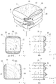
- Schematic perspective view (A diagram) showing a state in which the impact absorbing member is crushed in the axial direction by receiving an impact load
- BB arrow sectional view (B diagram) of FIG. A showing a state in which the impact absorbing member is crushed in the axial direction by receiving an impact load
- BB arrow sectional view (B diagram) of FIG. A CC arrow sectional view of FIG.
- D diagram DD sectional view
- E diagram EE sectional view
- the impact absorbing member according to Embodiment 1 of the present invention will be described with reference to FIGS.
- the X direction (horizontal direction), Y direction (vertical direction), and Z direction (length direction) shown in the figure correspond to the width direction, height direction, and front-rear direction of the vehicle to which the shock absorbing member is attached. is doing.
- the impact absorbing member 10 is a member that receives an impact load at the time of a vehicle collision and absorbs the impact load. As shown in FIG. 1, the bumper reinforcement 3 of the front bumper (not shown) and the vehicle 2 It is attached to the part of the crash box arranged between the left and right side members 5.
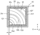
- the impact absorbing member 10 includes a cylindrical member 20, a wood 12 that is coaxially stored in the cylindrical member 20 in a non-contact state, and the cylindrical member 20 and the wood 12. It is comprised from the foamed foaming material 30 with which the clearance gap is filled.
- the tubular member 20 is an extruded product using an aluminum alloy, and as shown in FIG. 3, the cross-sectional shape (transverse cross-sectional shape) perpendicular to the axis is formed in a square prismatic shape.
- the vertical (Y direction) and horizontal (X direction) dimensions of the cylindrical member 20 are set to about 47 mm
- the length dimension (Z direction) is set to about 70 mm
- the wall thickness dimension is set to about 0.5 mm.
- the wall thickness of the cylindrical member 20 is preferably set within the range of about 0.4 mm to 1.1 mm.
- the wood 12 is formed in a prismatic shape having a square cross section, and the longitudinal (Y direction) and lateral (X direction) dimensions of the prism are the longitudinal dimensions of the cylindrical member 20.
- the value is set to a value smaller than the horizontal dimension by a certain dimension. That is, the inner wall upper surface 21u, the inner wall lower surface 21d, the inner wall left side surface 21f, and the inner wall right side surface 21r of the cylindrical member 20 in a state where the wood 12 is accommodated in the cylindrical member 20 and positioned coaxially and in phase.
- a gap S having a certain size is formed between the upper surface 12u, the lower surface 12d, the left side surface 12f, and the right side surface 12r of the wood 12.
- the vertical (Y direction) and horizontal (X direction) dimensions of the wood 12 are set to values such that the gap S is about 3 mm.
- the length dimension (dimension in the Z direction) of the wood 12 is set to a value equal to the length dimension (about 70 mm) in the axial direction of the tubular member 20.
- the wood 12 is formed in a prismatic shape so that the axial center direction of the annual ring 12k extends in the longitudinal direction (axial direction). For this reason, in a state where the wood 12 is stored in the cylindrical member 20, the axial center direction of the annual ring 12 k of the wood 12 substantially coincides with the axial direction of the cylindrical member 20.
- cedar is suitably used as the wood 12, for example, cedar is suitably used.
- the foam material 30 is a member that positions the wood 12 coaxially and in phase with the tubular member 20 and supports the wood 12 so that the wood 12 does not rattle.
- the foam material 30 hard foamed urethane foamed 5 to 30 times is used.
- foamed rigid foamed urethane is used with the wood 12 positioned coaxially and in phase with the cylindrical member 20.
- the gap S between the wood 12 and the cylindrical member 20 is filled by spraying or the like.
- the thickness of the foam material 30 is constant and about 3 mm in the circumferential direction.
- the main agent which is the hard foam urethane stock solution, and the curing agent are mixed and stirred, and the stock solution is used for the wood.
- a method of injecting into the gap S between 12 and the tubular member 20 is also possible.
- FIG. 5A shows measurement data when a foam material 30 (density 0.09 g / cm 3 ) having a foaming ratio of 10 is used for the impact absorbing member 10, for example.
- FIG. 5B shows, for example, a foamed material 30 (density 0.14 g / cm 3 ) having a foaming ratio of 5 times
- FIG. 5C shows a foamed material 30 having a foaming ratio of 30 times (density 0.03 g / cm 3 ). It is the measurement data when using.
- the vertical axis represents the magnitude of the impact load
- the horizontal axis represents the crushing amount (stroke) in the axial direction of the shock absorbing member 10.
- a gap S of about 3 mm that is uniform in the circumferential direction is formed between the outer surface of the wood 12 and the inner wall surface of the cylindrical member 20, and the foamed foam material 30 is filled in the gap S. ing.
- the foam material 30 is obtained by foaming hard foam urethane between 5 times and 30 times, the strength of the foam material 30 is necessary for positioning the wood 12 with respect to the tubular member 20. It becomes a state close to the minimum strength. For this reason, as shown in FIGS. 4A to 4E, when the tubular member 20 is crushed together with the wood 12, the foam material 30 does not hinder the deformation of the tubular member 20 on the radially inner side. Therefore, as shown in FIGS. 4D and 4E, the cylindrical member 20 is crushed in a bellows shape around the wood 12.
- the upper and lower portions of the tubular member 20 are each in the radial direction.
- the outer part is deformed outward, and the left part and the right part are deformed radially inward.
- the upper part and the lower part of the cylindrical member 20 swell in a mountain shape (refer FIG. 4 (B) (D)), and a left part and a right part are contacted with the outer surface of the timber 12. It becomes deformed into a groove shape (see FIGS. 4B and 4E).
- the upper and lower portions of the cylindrical member 20 are grooves until they come into contact with the outer surface of the wood 12.
- the left part and the right part are deformed so as to swell in a mountain shape.
- the third bending position L3 located behind the second bending position L2 is deformed in the same manner as the first bending position L1, and the fourth bending position L3 located behind the third bending position L3 is changed to the first bending position L3.
- the second bending position L2 is deformed.
- the cylindrical member 20 is collapsed in a bellows shape around the wood 12 in a state where the phase is shifted by about 90 ° between the upper part, the lower part, the left part, and the right part. Then, the cylindrical member 20 is crushed in a bellows shape around the wood 12 so that the cylindrical member 20 can prevent the wood 12 from falling. As a result, the wood 12 is reliably crushed in the axial direction, and as shown in FIG. 5, the impact load is absorbed by the stroke of the timber 12 being crushed.
- the expansion ratio of the foam material 30 when the expansion ratio of the foam material 30 is smaller than 5 times, the strength of the foam material 30 becomes higher than the allowable range, and the foam material 30 prevents deformation of the tubular member 20 in the radial direction, thereby The shaped member 20 does not collapse into a bellows shape. Moreover, when the expansion ratio of the foam material 30 is larger than 30 times, the strength of the foam material 30 is lowered from the allowable range, and the positioning property and the earthquake resistance of the wood 12 with respect to the tubular member 20 are deteriorated.
- the impact absorbing member 10 since the wood 12 housed in the tubular member 20 has a higher strength against the impact load than the tubular member 20, the impact load can be received mainly by the wood 12. Become.
- the foamed foam material 30 is filled between the outer side surface of the wood 12 and the inner wall surface of the cylindrical member 20, the wood 12 is securely in a non-contact state with respect to the cylindrical member 20. It becomes possible to position. Further, the foam material 30 does not prevent the tubular member 20 from being deformed radially inward when the tubular member 20 is crushed in the axial direction together with the wood 12 by an impact load.
- the cylindrical member 20 is crushed in a bellows shape around the wood 12.
- the timber 12 is supported from the surroundings in a well-balanced manner by the cylindrical member 20 crushed in a bellows shape, and is difficult to fall down.
- the load in the axial direction can be efficiently received by the wood 12, and the high load can be efficiently absorbed by the wood 12 and the cylindrical member 20 being crushed in the axial direction.
- the wood 12 is positioned with respect to the tubular member 20 by the foam material 30 with a structure in which the wood 12 is simply housed in the tubular member 20, the configuration is simple and the cost can be reduced.
- the foamed material 30 is filled in the gap S between the outer side surface of the wood 12 and the inner wall surface of the tubular member 20, the wood 12 is securely attached to the tubular member 20. In addition to being able to position, even when a vibration of a vehicle or the like is applied to the impact absorbing member 10, no vibration is generated between the tubular member 20 and the wood 12.
- the expansion ratio of the foam material 30 is set between about 5 times and about 30 times. For this reason, the strength of the foamed foam material 30 is close to the minimum strength necessary for positioning the wood 12 with respect to the tubular member 20.
- the foamed material 30 does not hinder the deformation of the cylindrical member 20 on the radially inner side.
- the cylindrical member 20 is formed in a square cylinder shape, the wood 12 is formed in a prismatic shape, and the thickness of the foamed material 30 is constant, the wood 12 and the cylindrical member 20 are even in the circumferential direction. It will be crushed.
- the cylindrical member 20 is an extruded product using an aluminum alloy, the wood 12 is a cedar material, and the foam material 30 is a hard foamed urethane having an expansion ratio of about 5 to 30 times. While being able to receive a load efficiently, the cylindrical member 20 is crushed bellows around the wood 12, and the wood 12 can be effectively supported from the surroundings.
- the present invention is not limited to the above-described embodiment, and modifications can be made without departing from the gist of the present invention.
- the example which inserts the square pillar-shaped wood 12 with respect to the rectangular cylindrical cylindrical member 20, and sets the thickness dimension of the foaming material 30 to about 3 mm was shown.
- the gap 30 between the wood 12 and the tubular member 20 can be set within the range of about 2 mm to about 4 mm, and the thickness of the foam 30 can be set between about 2 mm and about 4 mm. It is.
- the example in which the quadrangular prism-shaped wood 12 is inserted coaxially and in the same phase with respect to the rectangular tubular member 20 is shown, but the tubular member 20 and the wood 12 are not in contact with each other. If there is, it is acceptable to some extent that the axial center or phase between the cylindrical member 20 and the wood 12 is shifted.
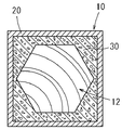
- the square pillar-shaped wood 12 was illustrated with respect to the rectangular tubular member 20, the hexagonal pillar-shaped wood 12 is used with respect to the rectangular tubular member 20, as shown in FIG.
- FIG. 7 it is also possible to use elliptical columnar wood 12 for the rectangular tubular member 20. Further, as shown in FIG.
Landscapes
- Engineering & Computer Science (AREA)
- Mechanical Engineering (AREA)
- General Engineering & Computer Science (AREA)
- Vibration Dampers (AREA)
Abstract
本発明は、簡易な構成で車両衝突時の高荷重を効率的に吸収できるようにすることを目的とする。 本発明に係る衝撃吸収部材は、軸方向から衝撃荷重を受けられるように配置され、衝撃荷重を受けて軸方向に潰れる筒状部材(20)と、筒状部材(20)に非接触な状態で収納されており、前記衝撃荷重に対する強度が筒状部材(20)よりも大きい木材(12)と、筒状部材(20)に対する木材(12)の位置決めが可能であり、発泡することで木材(12)の外側面と筒状部材(20)の内壁面との隙間に、部分的、あるいは全体に亘って充填される発泡材(30)とを有しており、発泡した発泡材(30)は、前記衝撃荷重で筒状部材(20)が木材(12)と共に軸方向に潰れる際、その筒状部材(20)が径方向内側に変形するのを妨げない強度であることを特徴とする。
Description
本発明は、車両衝突時等の衝撃荷重を受けてその衝撃荷重を効率的に吸収できるように構成された衝撃吸収部材に関する。
車両衝突時等の衝撃荷重を受けてその衝撃荷重を吸収できるように構成された衝撃吸収部材に関する技術が特許文献1に記載されている。
特許文献1に記載された衝撃吸収部材100は、図9に示すように、アルミニウム合金製の筒状のハウジング102と、そのハウジング102内に収納された高剛性の発泡弾性体104とから構成されている。この衝撃吸収部材100は、車両のバンパーやドアのインパクトビーム等に使用されており、衝突荷重を筒状のハウジング102の側面で受けてその車両衝突時の衝撃荷重及び振動エネルギーとを吸収できるように構成されている。
特許文献1に記載された衝撃吸収部材100は、図9に示すように、アルミニウム合金製の筒状のハウジング102と、そのハウジング102内に収納された高剛性の発泡弾性体104とから構成されている。この衝撃吸収部材100は、車両のバンパーやドアのインパクトビーム等に使用されており、衝突荷重を筒状のハウジング102の側面で受けてその車両衝突時の衝撃荷重及び振動エネルギーとを吸収できるように構成されている。
上記した衝撃吸収部材100では、車両の衝突荷重を主としてハウジング102で受ける構成であり、発泡弾性体104のみで前記衝突荷重を受けることはできない。したがって、前記衝撃吸収部材100を高荷重域で使用する場合には、筒状のハウジング102の強度を高める必要があり、そのハウジング102の肉厚寸法を増加させたり、ハウジング102の内部を仕切り壁等により複数に仕切る等の対策が必要になる。この結果、衝撃吸収部材100の重量が増加し、さらに構造が複雑になってコスト高となる。
本発明は、上記問題点を解決するためになされたものであり、本発明が解決しようとする課題は、簡易な構成で車両衝突時の高荷重を効率的に吸収できるようにすることである。
上記した課題は、各請求項の発明によって解決される。
請求項1の衝撃吸収部材は、軸方向から衝撃荷重を受けられるように配置され、前記衝撃荷重を受けて軸方向に潰れる筒状部材と、前記筒状部材に非接触な状態で収納されており、前記衝撃荷重に対する強度が前記筒状部材よりも大きい木材と、前記筒状部材に対する前記木材の位置決めが可能であり、発泡することで前記木材の外側面と前記筒状部材の内壁面との隙間に、部分的、あるいは全体に亘って充填される発泡材とを有しており、前記発泡した発泡材は、前記衝撃荷重で前記筒状部材が前記木材と共に軸方向に潰れる際、その筒状部材が径方向内側に変形するのを妨げない強度であることを特徴とする。
請求項1の衝撃吸収部材は、軸方向から衝撃荷重を受けられるように配置され、前記衝撃荷重を受けて軸方向に潰れる筒状部材と、前記筒状部材に非接触な状態で収納されており、前記衝撃荷重に対する強度が前記筒状部材よりも大きい木材と、前記筒状部材に対する前記木材の位置決めが可能であり、発泡することで前記木材の外側面と前記筒状部材の内壁面との隙間に、部分的、あるいは全体に亘って充填される発泡材とを有しており、前記発泡した発泡材は、前記衝撃荷重で前記筒状部材が前記木材と共に軸方向に潰れる際、その筒状部材が径方向内側に変形するのを妨げない強度であることを特徴とする。
本発明によると、筒状部材に収納されている木材が前記筒状部材よりも衝撃荷重に対する強度が大きいため、衝撃荷重を主として木材で受けられるようになる。また、木材の外側面と筒状部材の内壁面との間には、発泡した発泡材が充填されているため、木材を筒状部材に対して非接触の状態で確実に位置決めできるようになる。さらに、発泡材は、衝撃荷重で筒状部材が木材と共に軸方向に潰れる際、その筒状部材が径方向内側に変形するのを妨げない。したがって、前記筒状部材は前記木材の周囲でジャバラ状に潰れることができるようになる。これにより、木材はジャバラ状に潰れた筒状部材によって周囲からバランス良く支えられ、転倒し難くなる。この結果、前記木材により軸方向の荷重を効率的に受けられ、前記木材及び筒状部材が軸方向に潰れることで高荷重を効率的に吸収できるようになる。
また、筒状部材に木材を収納するだけでの構造で、前記筒状部材に対する木材の位置決めを発泡材で行うため、構成が簡単であり、コスト低減を図ることができる。
また、筒状部材に木材を収納するだけでの構造で、前記筒状部材に対する木材の位置決めを発泡材で行うため、構成が簡単であり、コスト低減を図ることができる。
請求項2の発明によると、木材の外側面と筒状部材の内壁面との隙間には、全体に亘って前記発泡した発泡材が充填されていることを特徴とする。
このため、筒状部材に対して木材を確実に位置決めできるとともに、車両等の振動が衝撃吸収部材に加わった場合でも筒状部材と木材間で振動が発生することがない。
このため、筒状部材に対して木材を確実に位置決めできるとともに、車両等の振動が衝撃吸収部材に加わった場合でも筒状部材と木材間で振動が発生することがない。
請求項3の発明によると、発泡材の発泡倍率は、約5倍から約30倍の間に設定されていることを特徴とする。
このため、発泡した発泡材の強度が、筒状部材に対して木材を位置決め等するために必要な最小限の強度に近くなり、前記衝撃荷重で前記筒状部材が前記木材と共に軸方向に潰れる際、その筒状部材が径方向内側に変形するのを妨げることがなくなる。
このため、発泡した発泡材の強度が、筒状部材に対して木材を位置決め等するために必要な最小限の強度に近くなり、前記衝撃荷重で前記筒状部材が前記木材と共に軸方向に潰れる際、その筒状部材が径方向内側に変形するのを妨げることがなくなる。
請求項4の発明によると、筒状部材は角筒形に形成されて、木材は角柱形に形成されており、前記発泡した発泡材の厚み寸法が一定であることを特徴とする。
このため、木材及び筒状部材が周方向において均等に潰れるようになる。
請求項5の発明によると、筒状部材はアルミ合金による成形品であり、木材は杉材であり、発泡材は硬質発泡ウレタンであることを特徴とする。
請求項6の発明によると、筒状部材の厚み寸法が約0.4mmから約1.1mmの範囲内であり、前記発泡した発泡材の厚み寸法が約2mmから約4mmの範囲内に設定されていることを特徴とする。
したがって、木材により大荷重を効率的に受けられるとともに、筒状部材が木材の周囲でジャバラ状に潰れ、その木材を回りから効果的に支えられるようになる。
このため、木材及び筒状部材が周方向において均等に潰れるようになる。
請求項5の発明によると、筒状部材はアルミ合金による成形品であり、木材は杉材であり、発泡材は硬質発泡ウレタンであることを特徴とする。
請求項6の発明によると、筒状部材の厚み寸法が約0.4mmから約1.1mmの範囲内であり、前記発泡した発泡材の厚み寸法が約2mmから約4mmの範囲内に設定されていることを特徴とする。
したがって、木材により大荷重を効率的に受けられるとともに、筒状部材が木材の周囲でジャバラ状に潰れ、その木材を回りから効果的に支えられるようになる。
本発明によると、簡易な構成で車両衝突時の大荷重を効率的に吸収できるようになる。
[実施形態1]
以下、図1から図8に基づいて本発明の実施形態1に係る衝撃吸収部材について説明する。
なお、図中に示すX方向(横方向)、Y方向(縦方向)、及びZ方向(長さ方向)は、衝撃吸収部材が取付けられる車両の幅方向、高さ方向、及び前後方向に対応している。
以下、図1から図8に基づいて本発明の実施形態1に係る衝撃吸収部材について説明する。
なお、図中に示すX方向(横方向)、Y方向(縦方向)、及びZ方向(長さ方向)は、衝撃吸収部材が取付けられる車両の幅方向、高さ方向、及び前後方向に対応している。
<衝撃吸収部材10の取付け部分概要について>
本実施形態に係る衝撃吸収部材10は、車両衝突時の衝撃荷重を受けてその衝撃荷重を吸収する部材であり、図1に示すように、フロントバンパ(図示省略)のバンパーリインフォース3と車両2の左右のサイドメンバ5との間に配置されるクラッシュボックスの部分に取付けられている。
本実施形態に係る衝撃吸収部材10は、車両衝突時の衝撃荷重を受けてその衝撃荷重を吸収する部材であり、図1に示すように、フロントバンパ(図示省略)のバンパーリインフォース3と車両2の左右のサイドメンバ5との間に配置されるクラッシュボックスの部分に取付けられている。
<衝撃吸収部材10の構成について>
衝撃吸収部材10は、図2、図3に示すように、筒状部材20と、その筒状部材20に非接触状態で同軸に収納される木材12と、筒状部材20と木材12との隙間に充填される発泡した発泡材30とから構成されている。
筒状部材20は、アルミ合金を使用した押出成形品であり、図3に示すように、軸心に対して直角な断面形状(横断面形状)が正方形の角筒形に形成されている。
ここで、筒状部材20の縦(Y方向)、横(X方向)寸法は約47mm、長さ寸法(Z方向)は約70mm、肉厚寸法は約0.5mm程度に設定されている。なお、筒状部材20の肉厚寸法は、約0.4mm~1.1mmの範囲内に設定するのが好ましい。
衝撃吸収部材10は、図2、図3に示すように、筒状部材20と、その筒状部材20に非接触状態で同軸に収納される木材12と、筒状部材20と木材12との隙間に充填される発泡した発泡材30とから構成されている。
筒状部材20は、アルミ合金を使用した押出成形品であり、図3に示すように、軸心に対して直角な断面形状(横断面形状)が正方形の角筒形に形成されている。
ここで、筒状部材20の縦(Y方向)、横(X方向)寸法は約47mm、長さ寸法(Z方向)は約70mm、肉厚寸法は約0.5mm程度に設定されている。なお、筒状部材20の肉厚寸法は、約0.4mm~1.1mmの範囲内に設定するのが好ましい。
木材12は、図2、図3に示すように、横断面形状が正方形の角柱形に形成されており、その角柱の縦(Y方向)、横(X方向)寸法が筒状部材20の縦、横寸法よりも一定寸法だけ小さな値に設定されている。即ち、木材12が筒状部材20に収納されて、同軸、かつ同位相に位置決めされた状態で、筒状部材20の内壁上面21u、内壁下面21d、内壁左側面21f、及び内壁右側面21rと、木材12の上面12u、下面12d、左側面12f、及び右側面12rとの間にはそれぞれ一定寸法の隙間Sが形成されるようになる。ここで、木材12の縦(Y方向)、横(X方向)寸法は、前記隙間Sが約3mmとなるような値に設定されている。
また、木材12の長さ寸法(Z方向の寸法)は、筒状部材20の軸方向の長さ寸法(約70mm)と等しい値に設定されている。
木材12は、年輪12kの軸心方向が長手方向(軸方向)に延びるように角柱形に成形されている。このため、木材12を筒状部材20に収納した状態で、その木材12の年輪12kの軸心方向が筒状部材20の軸方向とほぼ一致するようになる。
木材12としては、例えば、杉材が好適に使用される。
また、木材12の長さ寸法(Z方向の寸法)は、筒状部材20の軸方向の長さ寸法(約70mm)と等しい値に設定されている。
木材12は、年輪12kの軸心方向が長手方向(軸方向)に延びるように角柱形に成形されている。このため、木材12を筒状部材20に収納した状態で、その木材12の年輪12kの軸心方向が筒状部材20の軸方向とほぼ一致するようになる。
木材12としては、例えば、杉材が好適に使用される。
<発泡材30について>
発泡材30は、筒状部材20に対して木材12を同軸、かつ同位相に位置決めするとともに、筒状部材20に対して木材12がガタつかないように支持する部材である。発泡材30としては、5倍~30倍に発泡させた硬質発泡ウレタンが使用される。
発泡材30を木材12と筒状部材20との隙間Sに充填する方法としては、筒状部材20に対して木材12を同軸、かつ同位相に位置決めした状態で、発泡させた硬質発泡ウレタンを、例えば、スプレー等により木材12と筒状部材20との隙間Sに充填する。これにより、硬質発泡ウレタンが固化すると、木材12は筒状部材20に対してガタつきのない状態で、同軸、かつ同位相に位置決めされる。前述のように、木材12と筒状部材20との隙間Sは周方向に一定で約3mmに設定されているため、発泡材30の厚み寸法は周方向に一定で約3mmとなる。
ここで、スプレー等で硬質発泡ウレタンを木材12と筒状部材20との隙間Sに充填する代わりに、硬質発泡ウレタンの原液である主剤と硬化剤とを混合して攪拌し、この原液を木材12と筒状部材20との隙間Sに注入する方法でも可能である。
なお、発泡材30として硬質発泡ウレタンを使用する例を示したが、硬質発泡ウレタンの代わりに、発泡スチロール板等を木材12と筒状部材20との隙間Sに挿入することも可能である。
発泡材30は、筒状部材20に対して木材12を同軸、かつ同位相に位置決めするとともに、筒状部材20に対して木材12がガタつかないように支持する部材である。発泡材30としては、5倍~30倍に発泡させた硬質発泡ウレタンが使用される。
発泡材30を木材12と筒状部材20との隙間Sに充填する方法としては、筒状部材20に対して木材12を同軸、かつ同位相に位置決めした状態で、発泡させた硬質発泡ウレタンを、例えば、スプレー等により木材12と筒状部材20との隙間Sに充填する。これにより、硬質発泡ウレタンが固化すると、木材12は筒状部材20に対してガタつきのない状態で、同軸、かつ同位相に位置決めされる。前述のように、木材12と筒状部材20との隙間Sは周方向に一定で約3mmに設定されているため、発泡材30の厚み寸法は周方向に一定で約3mmとなる。
ここで、スプレー等で硬質発泡ウレタンを木材12と筒状部材20との隙間Sに充填する代わりに、硬質発泡ウレタンの原液である主剤と硬化剤とを混合して攪拌し、この原液を木材12と筒状部材20との隙間Sに注入する方法でも可能である。
なお、発泡材30として硬質発泡ウレタンを使用する例を示したが、硬質発泡ウレタンの代わりに、発泡スチロール板等を木材12と筒状部材20との隙間Sに挿入することも可能である。
<衝撃吸収部材10の働きについて>
次に、図4、図5に基づいて、衝撃吸収部材10の働きについて説明する。
ここで、図5(A)は、衝撃吸収部材10に、例えば、発泡倍率が10倍の発泡材30(密度0.09g/cm3)を使用したときの測定データである。図5(B)は、例えば、発泡倍率が5倍の発泡材30(密度0.14g/cm3)、図5(C)は発泡倍率が30倍の発泡材30(密度0.03g/cm3)を使用したときの測定データである。また、図5(A)~(C)における縦軸は衝撃荷重の大きさを表しており、横軸は衝撃吸収部材10の軸方向における潰れ量(ストローク)を表している。
車両2が前方衝突をして衝撃吸収部材10に対して軸方向から衝撃荷重が加わり、その衝撃荷重が、図5(A)~(C)に示すように、許容値H(例えば、5~6×10⁴N )を超えると、衝撃吸収部材10が軸方向に潰れて前記衝撃荷重が吸収される。即ち、衝撃吸収部材10を構成する木材12と筒状部材20等が前記衝撃荷重を受けて、その衝撃荷重により軸方向に潰れるようになる。
次に、図4、図5に基づいて、衝撃吸収部材10の働きについて説明する。
ここで、図5(A)は、衝撃吸収部材10に、例えば、発泡倍率が10倍の発泡材30(密度0.09g/cm3)を使用したときの測定データである。図5(B)は、例えば、発泡倍率が5倍の発泡材30(密度0.14g/cm3)、図5(C)は発泡倍率が30倍の発泡材30(密度0.03g/cm3)を使用したときの測定データである。また、図5(A)~(C)における縦軸は衝撃荷重の大きさを表しており、横軸は衝撃吸収部材10の軸方向における潰れ量(ストローク)を表している。
車両2が前方衝突をして衝撃吸収部材10に対して軸方向から衝撃荷重が加わり、その衝撃荷重が、図5(A)~(C)に示すように、許容値H(例えば、5~6×10⁴N )を超えると、衝撃吸収部材10が軸方向に潰れて前記衝撃荷重が吸収される。即ち、衝撃吸収部材10を構成する木材12と筒状部材20等が前記衝撃荷重を受けて、その衝撃荷重により軸方向に潰れるようになる。
前述のように、木材12の外側面と筒状部材20の内壁面との間には周方向に均等な約3mmの隙間Sが形成されて、その隙間Sに発泡した発泡材30が充填されている。ここで、発泡材30は、硬質発泡ウレタンを5倍~30倍の間で発泡させたものであるため、発泡材30の強度が筒状部材20に対して木材12を位置決め等するために必要な最小限の強度に近い状態となる。このため、図4(A)~(E)に示すように、筒状部材20が木材12と共に潰れる際、発泡材30が筒状部材20の径方向内側の変形を妨げることがない。したがって、図4(D)(E)に示すように、前記筒状部材20は木材12の周囲でジャバラ状に潰れるようになる。
即ち、衝撃吸収部材10の先端側の第1曲げ位置L1(図4(D)参照)では、例えば、図4(B)に示すように、筒状部材20の上部と下部とはそれぞれ径方向外側に変形し、左部と右部は径方向内側に変形する。これにより、第1曲げ位置L1では、筒状部材20の上部と下部とが山形に膨らみ(図4(B)(D)参照)、左部と右部は木材12の外側面に当接するまで溝状に変形するようになる(図4(B)(E)参照)。
また、第1曲げ位置L1の後側に位置する第2曲げ位置L2では、図4(C)に示すように、筒状部材20の上部と下部とは木材12の外側面に当接するまで溝状に変形し、左部と右部は山形に膨らむように変形する。
また、第2曲げ位置L2の後側に位置する第3曲げ位置L3では、第1曲げ位置L1と同様に変形し、第3曲げ位置L3の後側に位置する第4曲げ位置L3では、第2曲げ位置L2と同様に変形するようになる。
このように、筒状部材20は、上部、下部と左部、右部とで位相が約90°ずれた状態で、前記木材12の周囲でジャバラ状に潰れるようになる。
そして、筒状部材20が木材12の周囲でジャバラ状に潰れることで、その筒状部材20が木材12の転倒を防止できるようになる。この結果、木材12が軸方向に確実に潰れ、図5に示すように、木材12が潰れたストローク分だけ、衝撃荷重が吸収されるようになる。
なお、発泡材30の発泡倍率が5倍よりも小さい場合には、発泡材30の強度が許容範囲よりも高くなり、発泡材30が筒状部材20の径方向内側の変形を妨げて、筒状部材20がジャバラ状に潰れなくなる。また、発泡材30の発泡倍率が30倍よりも大きい場合には、発泡材30の強度が許容範囲より低下して筒状部材20に対する木材12の位置決め性、耐震性が低下する。
また、第1曲げ位置L1の後側に位置する第2曲げ位置L2では、図4(C)に示すように、筒状部材20の上部と下部とは木材12の外側面に当接するまで溝状に変形し、左部と右部は山形に膨らむように変形する。
また、第2曲げ位置L2の後側に位置する第3曲げ位置L3では、第1曲げ位置L1と同様に変形し、第3曲げ位置L3の後側に位置する第4曲げ位置L3では、第2曲げ位置L2と同様に変形するようになる。
このように、筒状部材20は、上部、下部と左部、右部とで位相が約90°ずれた状態で、前記木材12の周囲でジャバラ状に潰れるようになる。
そして、筒状部材20が木材12の周囲でジャバラ状に潰れることで、その筒状部材20が木材12の転倒を防止できるようになる。この結果、木材12が軸方向に確実に潰れ、図5に示すように、木材12が潰れたストローク分だけ、衝撃荷重が吸収されるようになる。
なお、発泡材30の発泡倍率が5倍よりも小さい場合には、発泡材30の強度が許容範囲よりも高くなり、発泡材30が筒状部材20の径方向内側の変形を妨げて、筒状部材20がジャバラ状に潰れなくなる。また、発泡材30の発泡倍率が30倍よりも大きい場合には、発泡材30の強度が許容範囲より低下して筒状部材20に対する木材12の位置決め性、耐震性が低下する。
<本実施形態に係る衝撃吸収部材10の長所について>
本実施形態に係る衝撃吸収部材10によると、筒状部材20に収納されている木材12がその筒状部材20よりも衝撃荷重に対する強度が大きいため、衝撃荷重を主として木材12で受けられるようになる。また、木材12の外側面と筒状部材20の内壁面との間には、発泡した発泡材30が充填されているため、木材12を筒状部材20に対して非接触の状態で確実に位置決めできるようになる。さらに、発泡材30は、衝撃荷重で筒状部材20が木材12と共に軸方向に潰れる際、その筒状部材20が径方向内側に変形するのを妨げない。したがって、前記筒状部材20は木材12の周囲でジャバラ状に潰れるようになる。これにより、木材12はジャバラ状に潰れた筒状部材20によって周囲からバランス良く支えられ、転倒し難くなる。この結果、木材12により軸方向の荷重を効率的に受けられるようになり、前記木材12及び筒状部材20が軸方向に潰れることで高荷重を効率的に吸収できるようになる。
また、筒状部材20に木材12を収納するだけでの構造で、前記筒状部材20に対する木材12の位置決めを発泡材30で行うため、構成が簡単であり、コスト低減を図ることができる。
本実施形態に係る衝撃吸収部材10によると、筒状部材20に収納されている木材12がその筒状部材20よりも衝撃荷重に対する強度が大きいため、衝撃荷重を主として木材12で受けられるようになる。また、木材12の外側面と筒状部材20の内壁面との間には、発泡した発泡材30が充填されているため、木材12を筒状部材20に対して非接触の状態で確実に位置決めできるようになる。さらに、発泡材30は、衝撃荷重で筒状部材20が木材12と共に軸方向に潰れる際、その筒状部材20が径方向内側に変形するのを妨げない。したがって、前記筒状部材20は木材12の周囲でジャバラ状に潰れるようになる。これにより、木材12はジャバラ状に潰れた筒状部材20によって周囲からバランス良く支えられ、転倒し難くなる。この結果、木材12により軸方向の荷重を効率的に受けられるようになり、前記木材12及び筒状部材20が軸方向に潰れることで高荷重を効率的に吸収できるようになる。
また、筒状部材20に木材12を収納するだけでの構造で、前記筒状部材20に対する木材12の位置決めを発泡材30で行うため、構成が簡単であり、コスト低減を図ることができる。
また、木材12の外側面と筒状部材20の内壁面との隙間Sには、全体に亘って発泡した発泡材30が充填されているため、筒状部材20に対して木材12を確実に位置決めできるとともに、車両等の振動が衝撃吸収部材10に加わった場合でも筒状部材20と木材12間で振動が発生することがない。
また、発泡材30の発泡倍率が約5倍から約30倍の間に設定されている。このため、発泡した発泡材30の強度が、筒状部材20に対して木材12を位置決め等するために必要な最小限の強度に近くなる。これにより、前記衝撃荷重で筒状部材20が木材12と共に軸方向に潰れる際、発泡材30が筒状部材20の径方向内側の変形を妨げることがない。
また、筒状部材20は角筒形に形成されて、木材12は角柱形に形成されており、発泡材30の厚み寸法が一定であるため、木材12及び筒状部材20が周方向において均等に潰れるようになる。
また、筒状部材20はアルミ合金を使用した押出成形品で、木材12は杉材であり、発泡材30は発泡倍率が約5~30倍の硬質発泡ウレタンであるため、前記木材12により大荷重を効率的に受けられるとともに、筒状部材20が木材12の周囲でジャバラ状に潰れ、その木材12を周囲から効果的に支えられるようになる。
また、発泡材30の発泡倍率が約5倍から約30倍の間に設定されている。このため、発泡した発泡材30の強度が、筒状部材20に対して木材12を位置決め等するために必要な最小限の強度に近くなる。これにより、前記衝撃荷重で筒状部材20が木材12と共に軸方向に潰れる際、発泡材30が筒状部材20の径方向内側の変形を妨げることがない。
また、筒状部材20は角筒形に形成されて、木材12は角柱形に形成されており、発泡材30の厚み寸法が一定であるため、木材12及び筒状部材20が周方向において均等に潰れるようになる。
また、筒状部材20はアルミ合金を使用した押出成形品で、木材12は杉材であり、発泡材30は発泡倍率が約5~30倍の硬質発泡ウレタンであるため、前記木材12により大荷重を効率的に受けられるとともに、筒状部材20が木材12の周囲でジャバラ状に潰れ、その木材12を周囲から効果的に支えられるようになる。
<変更例>
ここで、本発明は上記実施形態に限定されるものではなく、本発明の要旨を逸脱しない範囲における変更が可能である。例えば、本実施形態では、角筒状の筒状部材20に対して四角柱形の木材12を挿入して、発泡材30の厚み寸法を約3mmに設定する例を示した。しかし、発泡材30を木材12と筒状部材20との隙間Sを約2mmから約4mmの範囲内で設定し、発泡材30の厚み寸法を約2mmから約4mmの間で設定することも可能である。
また、本実施形態では、角筒状の筒状部材20に対して四角柱形の木材12を同軸、同位相で挿入する例を示したが、筒状部材20と木材12とが非接触であれば、筒状部材20と木材12との軸心、あるいは位相がずれることもある程度許容できる。
また、角筒状の筒状部材20に対して四角柱形の木材12を例示したが、図6に示すように、角筒状の筒状部材20に対して六角柱形の木材12を使用しても良いし、図7に示すように、角筒状の筒状部材20に対して楕円柱形の木材12を使用することも可能である。
さらに、図8に示すように、発泡材30を木材12と筒状部材20との隙間Sの軸方向両端部のみに充填する構造でも可能である。
また、筒状部材20としてアルミ合金の押出成形品を使用する例を示したが、アルミ押出グレードの素材を使用して筒状部材20を引き抜き成形することも可能である。
ここで、本発明は上記実施形態に限定されるものではなく、本発明の要旨を逸脱しない範囲における変更が可能である。例えば、本実施形態では、角筒状の筒状部材20に対して四角柱形の木材12を挿入して、発泡材30の厚み寸法を約3mmに設定する例を示した。しかし、発泡材30を木材12と筒状部材20との隙間Sを約2mmから約4mmの範囲内で設定し、発泡材30の厚み寸法を約2mmから約4mmの間で設定することも可能である。
また、本実施形態では、角筒状の筒状部材20に対して四角柱形の木材12を同軸、同位相で挿入する例を示したが、筒状部材20と木材12とが非接触であれば、筒状部材20と木材12との軸心、あるいは位相がずれることもある程度許容できる。
また、角筒状の筒状部材20に対して四角柱形の木材12を例示したが、図6に示すように、角筒状の筒状部材20に対して六角柱形の木材12を使用しても良いし、図7に示すように、角筒状の筒状部材20に対して楕円柱形の木材12を使用することも可能である。
さらに、図8に示すように、発泡材30を木材12と筒状部材20との隙間Sの軸方向両端部のみに充填する構造でも可能である。
また、筒状部材20としてアルミ合金の押出成形品を使用する例を示したが、アルミ押出グレードの素材を使用して筒状部材20を引き抜き成形することも可能である。
10・・・衝撃吸収部材
12・・・木材
20・・・筒状部材
30・・・発泡材
S・・・・隙間
12・・・木材
20・・・筒状部材
30・・・発泡材
S・・・・隙間
Claims (6)
- 軸方向から衝撃荷重を受けられるように配置され、前記衝撃荷重を受けて軸方向に潰れる筒状部材と、
前記筒状部材に非接触な状態で収納されており、前記衝撃荷重に対する強度が前記筒状部材よりも大きい木材と、
前記筒状部材に対する前記木材の位置決めが可能であり、発泡することで前記木材の外側面と前記筒状部材の内壁面との隙間に、部分的、あるいは全体に亘って充填される発泡材とを有しており、
前記発泡した発泡材は、前記衝撃荷重で前記筒状部材が前記木材と共に軸方向に潰れる際、その筒状部材が径方向内側に変形するのを妨げない強度であることを特徴とする衝撃吸収部材。 - 請求項1に記載された衝撃吸収部材であって、
前記木材の外側面と前記筒状部材の内壁面との隙間には、全体に亘って前記発泡した発泡材が充填されていることを特徴とする衝撃吸収部材。 - 請求項1又は請求項2のいずれかに記載された衝撃吸収部材であって、
前記発泡材の発泡倍率は、約5倍から約30倍の間に設定されていることを特徴とする衝撃吸収部材。 - 請求項1から請求項3のいずれかに記載された衝撃吸収部材であって、
前記筒状部材は角筒形に形成されて、前記木材は角柱形に形成されており、前記発泡した発泡材の厚み寸法が一定であることを特徴とする衝撃吸収部材。 - 請求項1から請求項4のいずれかに記載された衝撃吸収部材であって、
前記筒状部材はアルミ合金による成形品であり、
前記木材は杉材であり、
前記発泡材は硬質発泡ウレタンであることを特徴とする衝撃吸収部材。 - 請求項5に記載された衝撃吸収部材であって、
前記筒状部材の厚み寸法が約0.4mmから約1.1mmの範囲内であり、前記発泡した発泡材の厚み寸法が約2mmから約4mmの範囲内に設定されていることを特徴とする衝撃吸収部材。
Priority Applications (2)
| Application Number | Priority Date | Filing Date | Title |
|---|---|---|---|
| EP11863483.1A EP2698558A4 (en) | 2011-04-14 | 2011-11-14 | IMPACT DAMPING ELEMENT |
| US14/009,783 US20140124315A1 (en) | 2011-04-14 | 2011-11-14 | Shock-absorbing member |
Applications Claiming Priority (2)
| Application Number | Priority Date | Filing Date | Title |
|---|---|---|---|
| JP2011090154A JP2012218712A (ja) | 2011-04-14 | 2011-04-14 | 衝撃吸収部材 |
| JP2011-090154 | 2011-04-14 |
Publications (1)
| Publication Number | Publication Date |
|---|---|
| WO2012140803A1 true WO2012140803A1 (ja) | 2012-10-18 |
Family
ID=47009002
Family Applications (1)
| Application Number | Title | Priority Date | Filing Date |
|---|---|---|---|
| PCT/JP2011/076152 Ceased WO2012140803A1 (ja) | 2011-04-14 | 2011-11-14 | 衝撃吸収部材 |
Country Status (4)
| Country | Link |
|---|---|
| US (1) | US20140124315A1 (ja) |
| EP (1) | EP2698558A4 (ja) |
| JP (1) | JP2012218712A (ja) |
| WO (1) | WO2012140803A1 (ja) |
Cited By (1)
| Publication number | Priority date | Publication date | Assignee | Title |
|---|---|---|---|---|
| CN109774634A (zh) * | 2017-11-15 | 2019-05-21 | 丰田车体株式会社 | 车辆冲击吸收构件 |
Families Citing this family (8)
| Publication number | Priority date | Publication date | Assignee | Title |
|---|---|---|---|---|
| EP2786903B1 (en) * | 2011-11-29 | 2018-03-14 | Toyota Shatai Kabushiki Kaisha | Shock-absorbing member for vehicle |
| JP5776537B2 (ja) * | 2011-12-26 | 2015-09-09 | トヨタ車体株式会社 | 車両の衝撃吸収部材 |
| CN104968535B (zh) * | 2012-11-19 | 2017-03-08 | 丰田车体株式会社 | 冲击吸收机构 |
| JP6107289B2 (ja) * | 2013-03-25 | 2017-04-05 | トヨタ車体株式会社 | 衝撃吸収部材 |
| JP6398853B2 (ja) * | 2015-04-13 | 2018-10-03 | トヨタ車体株式会社 | 衝撃吸収部材 |
| JP6798457B2 (ja) * | 2017-09-15 | 2020-12-09 | トヨタ自動車株式会社 | バンパリインフォースメント |
| JP6729528B2 (ja) * | 2017-09-25 | 2020-07-22 | トヨタ車体株式会社 | 衝撃吸収部材、及びその製造方法 |
| JP6863219B2 (ja) * | 2017-10-13 | 2021-04-21 | トヨタ自動車株式会社 | 車両側部構造 |
Citations (3)
| Publication number | Priority date | Publication date | Assignee | Title |
|---|---|---|---|---|
| JP2001153169A (ja) * | 1999-11-26 | 2001-06-08 | Japan Automobile Research Inst Inc | ハイブリッド型衝撃吸収用部材 |
| JP2001246995A (ja) | 2000-03-02 | 2001-09-11 | Tokai Rubber Ind Ltd | 衝撃及び振動エネルギ吸収部材 |
| WO2002050449A1 (en) * | 2000-12-18 | 2002-06-27 | Toray Industries, Inc. | Impact energy absorber |
Family Cites Families (8)
| Publication number | Priority date | Publication date | Assignee | Title |
|---|---|---|---|---|
| US4138093A (en) * | 1977-05-18 | 1979-02-06 | Meinzer Lester N | Guard rail cell |
| JP3385798B2 (ja) * | 1995-05-22 | 2003-03-10 | 日本軽金属株式会社 | 自動車用フレーム材およびその製造方法 |
| US5746537A (en) * | 1996-03-20 | 1998-05-05 | The United States Of America As Represented By The Administrator Of The National Aeronautics And Space Administration | Crash-energy absorbing composite structure and method of fabrication |
| JP2001182769A (ja) * | 1999-12-27 | 2001-07-06 | Showa Alum Corp | 衝撃吸収部材 |
| DE10153025B4 (de) * | 2001-10-26 | 2007-09-20 | Daimlerchrysler Ag | Aufprallträger einer Fahrzeugkarosserie |
| US8181422B2 (en) * | 2008-12-23 | 2012-05-22 | Spirit Aerosystems, Inc. | Energy-absorbing structural composite element |
| DE102010015972B4 (de) * | 2010-03-15 | 2022-03-24 | Deutsches Zentrum für Luft- und Raumfahrt e.V. | Energieabsorptionsvorrichtung zur Absorption von Aufprallenergie und Fahrzeug mit mindestens einer Energieabsorptionsvorrichtung |
| JP5545259B2 (ja) * | 2010-12-01 | 2014-07-09 | トヨタ車体株式会社 | 衝撃吸収部材 |
-
2011
- 2011-04-14 JP JP2011090154A patent/JP2012218712A/ja active Pending
- 2011-11-14 WO PCT/JP2011/076152 patent/WO2012140803A1/ja not_active Ceased
- 2011-11-14 US US14/009,783 patent/US20140124315A1/en not_active Abandoned
- 2011-11-14 EP EP11863483.1A patent/EP2698558A4/en not_active Withdrawn
Patent Citations (3)
| Publication number | Priority date | Publication date | Assignee | Title |
|---|---|---|---|---|
| JP2001153169A (ja) * | 1999-11-26 | 2001-06-08 | Japan Automobile Research Inst Inc | ハイブリッド型衝撃吸収用部材 |
| JP2001246995A (ja) | 2000-03-02 | 2001-09-11 | Tokai Rubber Ind Ltd | 衝撃及び振動エネルギ吸収部材 |
| WO2002050449A1 (en) * | 2000-12-18 | 2002-06-27 | Toray Industries, Inc. | Impact energy absorber |
Non-Patent Citations (1)
| Title |
|---|
| See also references of EP2698558A4 |
Cited By (2)
| Publication number | Priority date | Publication date | Assignee | Title |
|---|---|---|---|---|
| CN109774634A (zh) * | 2017-11-15 | 2019-05-21 | 丰田车体株式会社 | 车辆冲击吸收构件 |
| CN109774634B (zh) * | 2017-11-15 | 2022-06-07 | 丰田车体株式会社 | 车辆冲击吸收构件 |
Also Published As
| Publication number | Publication date |
|---|---|
| EP2698558A1 (en) | 2014-02-19 |
| US20140124315A1 (en) | 2014-05-08 |
| JP2012218712A (ja) | 2012-11-12 |
| EP2698558A4 (en) | 2014-10-15 |
Similar Documents
| Publication | Publication Date | Title |
|---|---|---|
| WO2012140803A1 (ja) | 衝撃吸収部材 | |
| JP5545259B2 (ja) | 衝撃吸収部材 | |
| US8066322B2 (en) | Vehicle body structure | |
| US7533913B2 (en) | Front structure for car body | |
| US10330168B2 (en) | Bi-rectangular vehicle beam with cellular structure | |
| EP2202118A1 (en) | Impact absorbing member for vehicle | |
| KR101864809B1 (ko) | 개량된 에너지 흡수 시스템 | |
| JP6913029B2 (ja) | エネルギー吸収部材 | |
| KR20130007558A (ko) | 에너지 흡수 시스템 | |
| JP2011021673A (ja) | 衝撃吸収部材及び衝撃吸収構造 | |
| US10266207B2 (en) | Bi-hexagonal vehicle beam with cellular structure | |
| JP5288996B2 (ja) | 車両用衝撃吸収体 | |
| JP2014184899A (ja) | 衝撃吸収部材 | |
| CN103112418A (zh) | 溃缩盒及包括溃缩盒的车辆保险杠装置 | |
| KR101871605B1 (ko) | 사출공법을 이용한 차량용 크래쉬박스 일체형 범퍼 빔 시스템 | |
| JP5522114B2 (ja) | 衝撃吸収部材 | |
| JP4705360B2 (ja) | 車輌用バンパ及びその緩衝材 | |
| JP6206301B2 (ja) | 車両用フレーム構造 | |
| US20160280166A1 (en) | Vehicle bumper structure | |
| JP5210117B2 (ja) | 車両用バンパリィンフォース | |
| US9815496B2 (en) | Vehicle body | |
| KR101251299B1 (ko) | 차량용 크래쉬 박스 | |
| JP2008001204A (ja) | 車両用バンパー | |
| KR101137257B1 (ko) | 차량용 범퍼빔 유닛 | |
| JP4754996B2 (ja) | 車体用バンパ芯材及びこれを用いた車体用バンパ |
Legal Events
| Date | Code | Title | Description |
|---|---|---|---|
| 121 | Ep: the epo has been informed by wipo that ep was designated in this application |
Ref document number: 11863483 Country of ref document: EP Kind code of ref document: A1 |
|
| REEP | Request for entry into the european phase |
Ref document number: 2011863483 Country of ref document: EP |
|
| WWE | Wipo information: entry into national phase |
Ref document number: 2011863483 Country of ref document: EP |
|
| NENP | Non-entry into the national phase |
Ref country code: DE |
|
| WWE | Wipo information: entry into national phase |
Ref document number: 14009783 Country of ref document: US |