WO2012140827A1 - Réfrigérateur - Google Patents
Réfrigérateur Download PDFInfo
- Publication number
- WO2012140827A1 WO2012140827A1 PCT/JP2012/001559 JP2012001559W WO2012140827A1 WO 2012140827 A1 WO2012140827 A1 WO 2012140827A1 JP 2012001559 W JP2012001559 W JP 2012001559W WO 2012140827 A1 WO2012140827 A1 WO 2012140827A1
- Authority
- WO
- WIPO (PCT)
- Prior art keywords
- storage case
- seal member
- refrigerator
- shelf plate
- shelf
- Prior art date
- Legal status (The legal status is an assumption and is not a legal conclusion. Google has not performed a legal analysis and makes no representation as to the accuracy of the status listed.)
- Ceased
Links
Images

Classifications
-
- F—MECHANICAL ENGINEERING; LIGHTING; HEATING; WEAPONS; BLASTING
- F25—REFRIGERATION OR COOLING; COMBINED HEATING AND REFRIGERATION SYSTEMS; HEAT PUMP SYSTEMS; MANUFACTURE OR STORAGE OF ICE; LIQUEFACTION SOLIDIFICATION OF GASES
- F25D—REFRIGERATORS; COLD ROOMS; ICE-BOXES; COOLING OR FREEZING APPARATUS NOT OTHERWISE PROVIDED FOR
- F25D25/00—Charging, supporting, and discharging the articles to be cooled
- F25D25/02—Charging, supporting, and discharging the articles to be cooled by shelves
- F25D25/024—Slidable shelves
- F25D25/025—Drawers
Definitions
- the present invention relates to a refrigerator, and more particularly to a seal structure of a seal member provided in a drawer-type storage chamber.
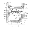
- FIG. 5 is a cross-sectional view of a conventional refrigerator.
- the vegetable compartment 4 has a drawer door 10 that opens and closes the front opening of the refrigerator.
- the storage container 11, which is a container disposed in the vegetable compartment 4, is interlocked by the drawer operation of the drawer door 10 and can be moved in the front-rear direction.
- An auxiliary container 14 is placed on the rear upper part of the storage container 11. The auxiliary container 14 is supported so as to be slidable in the front-rear direction with respect to the flange portion at the upper edge of the storage container 11.
- the rear wall of the storage container 11 is provided with a notch, and a seal packing 17 is fitted and attached to the flange provided on the left and right side edges and the bottom edge of the notch.
- the seal packing 17 is provided with an approximately semicircular arc thin elastic deformation portion on the upper surface thereof, and the elastic deformation portion elastically abuts on the protruding strip formed on the bottom edge of the auxiliary container.
- the gap is not formed between the notch and the auxiliary container.
- the auxiliary container 14 is placed on the upper part of the rear wall of the storage container 11, so that the rear wall of the storage container 11 and the auxiliary container 14 do not have a gap in the vertical direction by the seal packing 17. It is sealed.
- a seal member is not provided in the vertical gap generated between the storage container 11 that moves in the front-rear direction and the front end of the lid member 18 that is positioned above the storage container 11.
- seal packing 17 is disposed between the storage container 11 movable in the front-rear direction and the lid member 18, an elastic deformation portion that becomes a sealing surface, and a gap in the vertical direction between the storage container 11 and the lid member 18 is provided. It will be sealed so as not to occur.
- the elastically deforming portion has a substantially semicircular arc shape, when attached to a position below the lid member 18 and corresponding to the front side of the storage container 11, the elastically deforming portion protrudes downward below the lid member 18. Therefore, the seal surface may be worn by the back and forth movement of the storage container 11. Further, in the case of an elastically deformable member, the seal surface is in line contact, so that it shrinks to form a gap when the inside temperature changes, or conversely expands and the storage container 11 does not return to a predetermined position, and the door 10 is closed. There is also a risk that it will be impossible. Thus, since the vegetable compartment 4 is not sealed, there is a problem that the vegetable compartment 4 is dried or cannot be maintained at an appropriate temperature.
- This invention solves the conventional subject, and it aims at providing the refrigerator which suppressed the drying in a vegetable case and ensured sealing property.
- the refrigerator of the present invention is provided with a fin structure sealing member at the front edge and the rear edge of the shelf above the upper opening of the storage case, and the storage case is stored.
- the front wall portion of the seal member and the storage case and the rear wall portion of the seal member and the storage case are in contact with each other to close the gap between the shelf and the storage case.
- the refrigerator of the present invention is a food stored in the case because the gap between the case and the shelf can be sealed and the flow of cold air can be sealed by providing a sealing material on the shelf located above the case installed in the refrigerator compartment. The effect that can be protected from drying.
- FIG. 1 is a longitudinal sectional view of the refrigerator according to Embodiment 1 of the present invention.
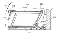
- FIG. 2 is a diagram illustrating a state in which the portion A of FIG. 1 is enlarged.
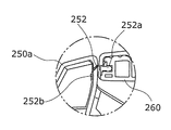
- FIG. 3 is a diagram illustrating a state in which a portion B in FIG. 2 is enlarged.
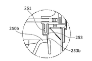
- FIG. 4 is a diagram illustrating a state in which a portion C in FIG. 2 is enlarged.
- FIG. 5 is a cross-sectional view of a conventional refrigerator.
- a first invention includes a shelf plate disposed in a storage chamber, a storage case stored so as to be able to be pulled out below the shelf plate, a mounting plate on which the storage case is mounted, and a front end of the shelf plate
- a first seal member that is fitted to the edge and seals a gap between the shelf and the storage case by contacting the front wall of the storage case; and a rear edge of the shelf
- a second seal member that seals a gap between the shelf plate and the storage case by contacting the rear wall portion of the storage case, and the front wall portion includes the shelf
- the rear wall portion is formed with a flange portion extending downward, and the first seal member is in contact with the front wall portion in the front-rear direction for sealing.
- the second seal member contacts and seals the flange portion in the vertical direction.For this reason, wear of the seal member can be prevented and a highly reliable seal structure can be formed.
- the said shelf board has a 1st connection member for providing said 1st seal member in a front-end edge part, Said 1st seal
- the member is a first base fixed by being press-fitted into a groove provided in the first connection member, one end extending downward while being curved forward, and the other end is A first fin portion that is integrally formed with the first base portion to form a seal surface. For this reason, the clearance gap between the front wall part of a storage case and the front-end edge part of a shelf board can be sealed because a surface contact
- 3rd invention is invention concerning 1st or 2nd invention, Comprising: Furthermore, the said shelf has a 2nd connection member for providing said 2nd sealing member in a rear-end edge part,
- the two seal members are a second base fixed by sandwiching the two connection members, a free end having one end extending substantially vertically downward, and the other end integrally formed with the second base. And a second fin portion that forms a sealing surface. For this reason, the sealing property with the rear wall surface of a storage case is securable.
- FIG. 1 is a longitudinal sectional view of the refrigerator according to Embodiment 1 of the present invention.
- the refrigerator 100 includes a plurality of storage compartments in a heat insulating box body 101 that separates the inside and the outside of the refrigerator 100 in a heat insulating state.
- the storage compartment divided into a plurality of parts in the refrigerator 100 may be referred to as being distinguished from the refrigerator compartment 104, the vegetable compartment 108, the freezer compartment 107, etc. depending on its function (cooling temperature).
- the front opening of the refrigerator compartment 104 located at the top of the refrigerator 100 is provided with a rotary heat insulating door 104a filled with a foam heat insulating material such as urethane to form a shelf-shaped storage space.
- the vegetable compartment 108 and the freezer compartment 107 arranged below the refrigerator compartment 104 are drawer-type storage spaces.
- the heat insulation box 101 is a rectangular parallelepiped box that is formed by filling a heat insulation material 101b such as hard foamed urethane between a metal outer box 102 and a resin inner box 103, for example. .
- the heat insulating box 101 has a function of blocking heat that tends to flow into the heat insulating box 101 from the outside atmosphere (atmosphere).
- the refrigerated room 104 is a storage room that is maintained at a low temperature so that the contents are not frozen for refrigerated storage.
- the specific room temperature set for the refrigerator compartment 104 is normally 1 to 5 ° C.
- the vegetable room 108 is a storage room that is disposed above the heat-insulating partition wall 110 that insulates the freezing room 107 vertically and below the refrigerator compartment 104 and is mainly intended for refrigeration of vegetables.
- the vegetable compartment 108 is set to a temperature that is equal to or slightly higher than that of the refrigerator compartment 104.
- the specific room temperature in which the vegetable room 108 is set is 2 ° C. to 7 ° C. In the vegetable compartment 108, the freshness of the leafy vegetables can be maintained for a longer period as the temperature is lowered in the set temperature range.
- the freezer compartment 107 is a storage room set in a freezing temperature zone.
- the room temperature is usually set to ⁇ 22 to ⁇ 18 ° C. for freezing storage, but in order to improve the freezing preservation state, for example, a low temperature of ⁇ 30 to ⁇ 25 ° C. It may be set to.
- FIG. 2 is an enlarged view of part A in FIG. 3 is an enlarged view of a portion B in FIG. 2, and FIG. 4 is an enlarged view of a portion C in FIG.
- the storage case 250 is a container for storing beverages filled with vegetables or plastic bottles, and is a box having an upper surface opened.
- the storage case 250 is installed between the heat insulating partition wall 110 and the shelf board 251.
- the shelf board 251 has a structure that closes the upper surface opening of the storage case 250.
- the storage case 250 is mounted on the heat insulating partition wall 110 as a mounting plate serving as a bottom surface of the refrigerator compartment 104 and is configured to be movable in the front-rear direction.
- a first seal member 252 is attached to the front edge portion of the shelf board 251 through a first connection member 260 by fitting.
- the first seal member 252 includes a first base portion 252a and a first fin portion 252b, and the first base portion 252a and the first fin portion 252b are integrally formed.
- the first seal member 252 is fixed to the front end edge of the storage case 250 by press-fitting the first base 252a into a groove provided in the first connection member 260 connected to the front end edge of the storage case 250.
- the first base portion 252a is formed with an anchor portion for preventing removal after press-fitting.
- the first fin portion 252b extends toward the opening of the vegetable compartment 108 and is curved in an arc shape toward the opening side of the refrigerator compartment 104.
- the first fin portion 252b is made of a soft resin, and the end portion on the opposite side to the first base portion 252a is a free end.
- the storage case front surface portion 250 a constituting the front wall of the storage case 250 rises upward from below and forms a folded portion that is folded back toward the front side at a position above the shelf 251.
- the folded portion is a handle portion that allows the storage case 250 to move in the front-rear direction.
- the first fin portion 252b abuts the storage case front surface portion 250a in the front-rear direction, so that the gap between the shelf board 251 and the storage case 250 is sealed.
- a second seal member 253 is attached to the rear end edge portion of the shelf board 251 through the second connection member 261 by fitting.
- the second seal member 253 includes a second base portion 253a and a second fin portion 253b, and the second base portion 253a and the second fin portion 253b are integrally molded.
- the second seal member 253 is fixed to the rear end edge portion of the storage case 250 by sandwiching the second connection member 261 having the second base portion 253 a connected to the rear end edge portion of the storage case 250.
- the engaging portion of the second connection member 261 to which the second seal member 253 is fixed extends downward in the vertical direction.
- the second seal member 253 extends further downward from the engaging portion of the second connection member 261. That is, the second fin portion 253b extends downward from the engaging portion of the second connection member 261.
- a flange portion 250b is formed to extend downward at a rear end edge portion (rear wall portion of the storage case 250) of the upper surface opening of the storage case 250, and a second fin portion 253b is formed on the flange portion 250b. By abutting in the vertical direction, the gap between the rear portion of the shelf board 251 and the storage case 250 is sealed.
- the cool air cooled by the heat exchange between the air and the refrigerant in the cooler 270 of the cooler chamber disposed behind the freezer compartment 107 is operated by the blower 271 at the top of the cooler 270. Accordingly, the refrigerant is distributed to the refrigerator compartment duct 272 extending upward from the refrigerator compartment and communicating with the refrigerator compartment 104 and the freezer compartment 107.
- the cold air guided to the refrigerator compartment duct 272 is discharged into the refrigerator compartment 104, and after being discharged, is sucked into a suction port 273 (see later) disposed behind the vegetable compartment 108, and then returns to the duct 275. (Refer to the description below) and the heat exchange is again performed by the cooler 270.
- the first seal member 252 is fixed to the front edge of the shelf plate 251 via the second connection member 261, and is formed so that the first fin portion 252b abuts the storage case front surface portion 250a in the front-rear direction. ing. For this reason, the 1st seal member 252 can be made into the state which sealed the clearance gap produced on the front side between the storage case 250 which comprises the vegetable compartment 108, and the shelf board 251 used as the top
- the second seal member 253 is fixed to the rear edge of the shelf plate 251 via the second connection member 261, and the second fin portion 253b contacts the flange portion 250b of the storage case 250 in the vertical direction. It is formed to touch. For this reason, the 2nd sealing member 253 can be made into the state which sealed the clearance gap produced between the storage case 250 which comprises the vegetable compartment 108, and the shelf board 251 used as the top
- the first seal member 252 and the second seal member 253 seal the front and rear gaps formed between the storage case 250 and the shelf board 251 constituting the vegetable compartment 108, so that the upper refrigerator compartment The cool air circulated downward from 104 is not guided into the storage case 250, and drying of vegetables stored in the vegetable compartment 108 can be prevented.
- a gap is formed between the lower surface of the storage case 250 and the lower heat insulating partition wall 110 as a cold air return duct 275 circulated through the refrigerator compartment 104.
- the cold air that has passed through the return duct 275 is sucked into the suction port 273 formed at the rear of the vegetable compartment 108, that is, at the rear of the storage case 250.
- the vegetables in the storage case 250 are not directly exposed to cold air, so that drying and low-temperature obstacles such as the vegetables in the storage case 250 can be reduced, and the freshness is improved because they are indirectly cooled. Can be maintained.
- first seal member 252 is in contact with the front surface portion 250a of the storage case because the first fin portion 252b is elastically deformed while curving from the second connection member 261 at the front edge of the shelf 251 to the near side.
- the storage case front surface portion 250a is brought into close contact with the storage case front surface portion 250a so as not to be elastically deformed to cause a gap between the storage case front surface portion 250a and the shelf board 251.
- the second seal member 253 has a second fin portion 253b that extends vertically downward from the second connection member 261 at the rear end edge of the shelf plate 251, and therefore, the flange portion at the rear end edge portion of the shelf plate 251.
- the second fin portion 253b is elastically deformed and press-contacted so as to hold down the flange portion 250b at the rear end edge of the storage case 250. Accordingly, the second seal member 253 is in close contact with the flange portion 250b so that no gap is generated between the flange portion 250b at the rear end edge portion of the storage case 250 and the shelf board 251.
- the first seal member 252 abuts while pressing the storage case front portion 250a in the front direction. . Therefore, in the state where the storage case 250 is pulled out, the variation in the distance between the storage case 250 and the shelf plate 251 or the shape of the first seal member 252 (that is, from the base 252a to the first fin portion 252b). Even if there is a variation in the distance), the sealing performance can be easily secured.
- the second seal member 253 is in contact with the upper portion of the flange portion 250b of the storage case 250 for sealing. That is, the second seal member 253 seals against the storage case 250 while suppressing the storage case 250 in a different direction from the first seal member 252, so that even if the storage case 250 is pushed forward by the elastic force of the first seal member 252. It is possible to reduce the occurrence of a gap between the flange portion 250b and the shelf board 251.
- the second seal member 253 disposed in the back part (rear side) of the vegetable compartment 108 is fixed to the second connection member 261 by the second base portion 253a sandwiching the second connection member 261. Therefore, workability can be improved.
- the second seal member 253 sandwiches the second base portion 253a from below to above the second connecting member 261 extending downward. For this reason, even if it repeats that the flange part 250b contact
- first base portion 252a of the first seal member 252 is fixed by being press-fitted in the front-rear direction with respect to the front end edge portion of the first connection member 260. For this reason, even if the storage case front surface portion 250a contacts the first fin portion 252b, stress is applied to the first seal member 252 in the front-rear direction. For this reason, it is possible to prevent the first seal member 252 from coming off due to an impact. Furthermore, since the anchor portion is formed on the first base portion 252a of the first seal member 252, it is possible to prevent further detachment.
- the refrigerator according to the present invention can secure the sealing property of the storage case, the same effect can be obtained even in a storage case used for commercial refrigerators and cold storages.
Landscapes
- Engineering & Computer Science (AREA)
- Chemical & Material Sciences (AREA)
- Combustion & Propulsion (AREA)
- Physics & Mathematics (AREA)
- Mechanical Engineering (AREA)
- Thermal Sciences (AREA)
- General Engineering & Computer Science (AREA)
- Cold Air Circulating Systems And Constructional Details In Refrigerators (AREA)
- Refrigerator Housings (AREA)
Abstract
L'invention concerne un réfrigérateur qui comporte, afin d'empêcher la dessiccation dans un bac à légumes et d'assurer l'étanchéité : une tablette (251) d'étagère ; un bac (250) de rangement rangé sous la tablette d'étagère de manière extractible ; une paroi (110) de compartiment à isolation thermique sur laquelle est disposée une surface inférieure du bac de rangement ; un premier élément (252) d'étanchéité monté sur une partie de bord avant de la tablette d'étagère et obturant un interstice avec la tablette d'étagère en prenant appui sur une partie de paroi avant du bac de rangement ; et un deuxième élément (253) d'étanchéité monté sur une partie de bord arrière de la tablette d'étagère et obturant un interstice avec la tablette d'étagère en prenant appui sur une partie de paroi arrière du bac de rangement. La partie de paroi avant s'étend vers le haut au-delà de la tablette d'étagère, tandis que la partie de paroi arrière comprend une partie (250b) de rebord s'étendant vers le bas. Le premier élément d'étanchéité prend appui sur la partie de paroi avant dans une direction avant-arrière pour assurer l'étanchéité. Le deuxième élément d'étanchéité prend appui sur la partie de rebord dans une direction haut-bas pour assurer l'étanchéité.
Applications Claiming Priority (2)
| Application Number | Priority Date | Filing Date | Title |
|---|---|---|---|
| JP2011-088740 | 2011-04-13 | ||
| JP2011088740A JP2012220148A (ja) | 2011-04-13 | 2011-04-13 | 冷蔵庫 |
Publications (1)
| Publication Number | Publication Date |
|---|---|
| WO2012140827A1 true WO2012140827A1 (fr) | 2012-10-18 |
Family
ID=47009024
Family Applications (1)
| Application Number | Title | Priority Date | Filing Date |
|---|---|---|---|
| PCT/JP2012/001559 Ceased WO2012140827A1 (fr) | 2011-04-13 | 2012-03-07 | Réfrigérateur |
Country Status (2)
| Country | Link |
|---|---|
| JP (1) | JP2012220148A (fr) |
| WO (1) | WO2012140827A1 (fr) |
Cited By (1)
| Publication number | Priority date | Publication date | Assignee | Title |
|---|---|---|---|---|
| EP2813789A3 (fr) * | 2013-06-12 | 2015-04-29 | Indesit Company Beyaz Esya San.Ve Tic A.S. | Exécution de boîte de bac à légumes pour réfrigérateur |
Families Citing this family (1)
| Publication number | Priority date | Publication date | Assignee | Title |
|---|---|---|---|---|
| JP6223265B2 (ja) * | 2014-04-14 | 2017-11-01 | 三菱電機株式会社 | 冷蔵庫 |
Citations (6)
| Publication number | Priority date | Publication date | Assignee | Title |
|---|---|---|---|---|
| JPS5637477A (en) * | 1980-08-08 | 1981-04-11 | Sharp Kk | Device for attaching*detaching container for refrigerator |
| JPS58173370A (ja) * | 1982-04-05 | 1983-10-12 | 松下冷機株式会社 | 冷蔵庫 |
| JPS63113886U (fr) * | 1987-01-16 | 1988-07-22 | ||
| JPH0210083A (ja) * | 1988-06-28 | 1990-01-12 | Matsushita Refrig Co Ltd | 冷蔵庫等の扉 |
| JPH02136676A (ja) * | 1988-11-18 | 1990-05-25 | Matsushita Refrig Co Ltd | 冷蔵庫 |
| JPH11270957A (ja) * | 1998-03-24 | 1999-10-05 | Matsushita Refrig Co Ltd | 冷蔵庫 |
-
2011
- 2011-04-13 JP JP2011088740A patent/JP2012220148A/ja not_active Withdrawn
-
2012
- 2012-03-07 WO PCT/JP2012/001559 patent/WO2012140827A1/fr not_active Ceased
Patent Citations (6)
| Publication number | Priority date | Publication date | Assignee | Title |
|---|---|---|---|---|
| JPS5637477A (en) * | 1980-08-08 | 1981-04-11 | Sharp Kk | Device for attaching*detaching container for refrigerator |
| JPS58173370A (ja) * | 1982-04-05 | 1983-10-12 | 松下冷機株式会社 | 冷蔵庫 |
| JPS63113886U (fr) * | 1987-01-16 | 1988-07-22 | ||
| JPH0210083A (ja) * | 1988-06-28 | 1990-01-12 | Matsushita Refrig Co Ltd | 冷蔵庫等の扉 |
| JPH02136676A (ja) * | 1988-11-18 | 1990-05-25 | Matsushita Refrig Co Ltd | 冷蔵庫 |
| JPH11270957A (ja) * | 1998-03-24 | 1999-10-05 | Matsushita Refrig Co Ltd | 冷蔵庫 |
Cited By (1)
| Publication number | Priority date | Publication date | Assignee | Title |
|---|---|---|---|---|
| EP2813789A3 (fr) * | 2013-06-12 | 2015-04-29 | Indesit Company Beyaz Esya San.Ve Tic A.S. | Exécution de boîte de bac à légumes pour réfrigérateur |
Also Published As
| Publication number | Publication date |
|---|---|
| JP2012220148A (ja) | 2012-11-12 |
Similar Documents
| Publication | Publication Date | Title |
|---|---|---|
| EP2719979A1 (fr) | Réfrigérateur pour empêcher l'humidification sur un joint de porte | |
| WO2011118137A1 (fr) | Réfrigérateur | |
| US10415875B2 (en) | Sealed crisper | |
| US20110011121A1 (en) | Refrigerator having the partition member | |
| JP2013036665A (ja) | 冷蔵庫 | |
| JP2012063123A (ja) | 冷蔵庫 | |
| JP5882808B2 (ja) | 冷蔵庫 | |
| WO2012140827A1 (fr) | Réfrigérateur | |
| JP2017190875A (ja) | 冷蔵庫 | |
| JP2017194257A (ja) | 冷蔵庫 | |
| JP2014052098A (ja) | 冷蔵庫 | |
| CN203274396U (zh) | 冷藏库 | |
| JP5898806B2 (ja) | 冷蔵庫 | |
| JP4480666B2 (ja) | 冷蔵庫用載置棚及びそれを用いた冷蔵庫 | |
| JP5797969B2 (ja) | 冷蔵庫 | |
| JP2013057472A (ja) | 冷蔵庫 | |
| JP2010091213A (ja) | 冷蔵庫 | |
| CN117120793B (zh) | 搁板构件及冰箱 | |
| JP7610836B2 (ja) | 棚部材 | |
| JP6675211B2 (ja) | 冷蔵庫 | |
| JP6138627B2 (ja) | 冷蔵庫 | |
| JP6072633B2 (ja) | 冷蔵庫 | |
| JP6039924B2 (ja) | 冷蔵庫 | |
| JP6105232B2 (ja) | 冷蔵庫 | |
| JP2025113019A (ja) | 冷蔵庫 |
Legal Events
| Date | Code | Title | Description |
|---|---|---|---|
| 121 | Ep: the epo has been informed by wipo that ep was designated in this application |
Ref document number: 12771710 Country of ref document: EP Kind code of ref document: A1 |
|
| NENP | Non-entry into the national phase |
Ref country code: DE |
|
| 122 | Ep: pct application non-entry in european phase |
Ref document number: 12771710 Country of ref document: EP Kind code of ref document: A1 |