WO2012140879A1 - Engin de chantier hybride - Google Patents
Engin de chantier hybride Download PDFInfo
- Publication number
- WO2012140879A1 WO2012140879A1 PCT/JP2012/002507 JP2012002507W WO2012140879A1 WO 2012140879 A1 WO2012140879 A1 WO 2012140879A1 JP 2012002507 W JP2012002507 W JP 2012002507W WO 2012140879 A1 WO2012140879 A1 WO 2012140879A1
- Authority
- WO
- WIPO (PCT)
- Prior art keywords
- engine
- housing
- motor housing
- motor
- stator
- Prior art date
- Legal status (The legal status is an assumption and is not a legal conclusion. Google has not performed a legal analysis and makes no representation as to the accuracy of the status listed.)
- Ceased
Links
Images

Classifications
-
- H—ELECTRICITY
- H02—GENERATION; CONVERSION OR DISTRIBUTION OF ELECTRIC POWER
- H02K—DYNAMO-ELECTRIC MACHINES
- H02K5/00—Casings; Enclosures; Supports
- H02K5/04—Casings or enclosures characterised by the shape, form or construction thereof
-
- E—FIXED CONSTRUCTIONS
- E02—HYDRAULIC ENGINEERING; FOUNDATIONS; SOIL SHIFTING
- E02F—DREDGING; SOIL-SHIFTING
- E02F9/00—Component parts of dredgers or soil-shifting machines, not restricted to one of the kinds covered by groups E02F3/00 - E02F7/00
- E02F9/08—Superstructures; Supports for superstructures
- E02F9/0858—Arrangement of component parts installed on superstructures not otherwise provided for, e.g. electric components, fenders, air-conditioning units
- E02F9/0866—Engine compartment, e.g. heat exchangers, exhaust filters, cooling devices, silencers, mufflers, position of hydraulic pumps in the engine compartment
-
- H—ELECTRICITY
- H02—GENERATION; CONVERSION OR DISTRIBUTION OF ELECTRIC POWER
- H02K—DYNAMO-ELECTRIC MACHINES
- H02K5/00—Casings; Enclosures; Supports
- H02K5/04—Casings or enclosures characterised by the shape, form or construction thereof
- H02K5/20—Casings or enclosures characterised by the shape, form or construction thereof with channels or ducts for flow of cooling medium
- H02K5/203—Casings or enclosures characterised by the shape, form or construction thereof with channels or ducts for flow of cooling medium specially adapted for liquids, e.g. cooling jackets
-
- B—PERFORMING OPERATIONS; TRANSPORTING
- B60—VEHICLES IN GENERAL
- B60K—ARRANGEMENT OR MOUNTING OF PROPULSION UNITS OR OF TRANSMISSIONS IN VEHICLES; ARRANGEMENT OR MOUNTING OF PLURAL DIVERSE PRIME-MOVERS IN VEHICLES; AUXILIARY DRIVES FOR VEHICLES; INSTRUMENTATION OR DASHBOARDS FOR VEHICLES; ARRANGEMENTS IN CONNECTION WITH COOLING, AIR INTAKE, GAS EXHAUST OR FUEL SUPPLY OF PROPULSION UNITS IN VEHICLES
- B60K1/00—Arrangement or mounting of electrical propulsion units
- B60K2001/003—Arrangement or mounting of electrical propulsion units with means for cooling the electrical propulsion units
-
- B—PERFORMING OPERATIONS; TRANSPORTING
- B60—VEHICLES IN GENERAL
- B60K—ARRANGEMENT OR MOUNTING OF PROPULSION UNITS OR OF TRANSMISSIONS IN VEHICLES; ARRANGEMENT OR MOUNTING OF PLURAL DIVERSE PRIME-MOVERS IN VEHICLES; AUXILIARY DRIVES FOR VEHICLES; INSTRUMENTATION OR DASHBOARDS FOR VEHICLES; ARRANGEMENTS IN CONNECTION WITH COOLING, AIR INTAKE, GAS EXHAUST OR FUEL SUPPLY OF PROPULSION UNITS IN VEHICLES
- B60K1/00—Arrangement or mounting of electrical propulsion units
- B60K2001/003—Arrangement or mounting of electrical propulsion units with means for cooling the electrical propulsion units
- B60K2001/006—Arrangement or mounting of electrical propulsion units with means for cooling the electrical propulsion units the electric motors
Definitions
- the present invention relates to a hybrid construction machine including an engine, a generator motor connected to the engine, and a means for cooling the generator motor.
- the background art will be described by taking as an example a hybrid excavator having a power unit configured by connecting an engine, a generator motor, and a hydraulic pump in series.
- a generator motor and a hydraulic pump are connected to the engine.
- the hydraulic actuator is driven by the oil discharged from the hydraulic pump.
- the battery is charged by operating the generator motor as a generator, and the engine is assisted by operating the generator motor as a motor with the electric power of the capacitor when appropriate.
- a pump device in which a refrigerant passage is provided in an electric motor housing is known (see Patent Document 1).
- the stator that is, the entire generator motor is cooled by heat exchange between a coolant such as water and the stator.
- the refrigerant passage be provided on the outer periphery of the stator in terms of cooling efficiency.
- the refrigerant passage cannot be provided on the outer periphery of the stator. For this reason, it is necessary to provide the refrigerant passage offset in the axial direction with respect to the outer periphery of the stator (the coupling surface between the engine housing and the electric motor housing).
- An object of the present invention is to provide a hybrid construction machine capable of efficiently cooling a generator motor while keeping the total length of a power unit short.
- the present invention is a hybrid construction machine, which has an engine having a crankshaft and an engine housing, a rotor connected to the crankshaft, and a radially outer position of the rotor.
- a generator motor having an electric motor housing that houses the rotor and the stator, and the engine housing and the electric motor housing are coupled to the engine side of the engine housing at a radially outer position of the stator.
- an electric motor side coupling surface of the electric motor housing are coupled to each other, and the electric motor housing projects from the inner peripheral edge of the electric motor side coupling surface to the engine side in the axial direction over the entire circumference around the axis.
- An overhanging portion that fits into the engine housing, and the stator.
- a hybrid construction machine that is disposed at a position shifted in the axial direction with respect to a coupling surface.
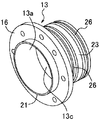
- FIG. 2 is a perspective view of the motor housing shown in FIG.
- the hybrid excavator includes a power unit configured by connecting an engine 1, a generator motor 2, and a hydraulic pump 3 in series.
- the hybrid excavator includes an engine 1, a generator motor 2 connected to the engine 1, a hydraulic pump 3 connected to the generator motor 2, the engine 1, and a generator motor. 2, a flywheel 5 provided between the generator motor 2, a coupling 7 provided between the generator motor 2 and the hydraulic pump 3, a refrigerant passage 22 for cooling the generator motor 2, and a refrigerant passage 22. And a heat insulating material 17 provided between the engine 1 and the generator motor 2, and a heat insulating material 20 provided between the generator motor 2 and the hydraulic pump 3.
- the engine 1 includes a crankshaft 4 that is an output shaft of the engine 1 and an engine housing 12 that houses main components of the engine.
- the flywheel 5 is attached to the crankshaft 4 of the engine 1.
- the generator motor 2 includes a rotor 30 connected to the crankshaft 4, a stator 31 disposed on the outer periphery of the rotor, and a motor housing that houses the rotor 30 and the stator 31 and is coupled to the engine housing 12 on the outer periphery of the stator 31.
- the rotor 30 includes a rotor shaft 6 connected to the flywheel 5 and a rotor core 9 provided on the outer periphery of the rotor shaft 6.
- the stator 31 includes a stator core 10 provided on the outer periphery of the rotor 30 and a coil 11 wound around the stator core 10.
- the hydraulic pump 3 has a pump shaft 8 that is rotated by the power of the engine 1 and the power of the generator motor 2, and a pump housing 14 that houses the main components of the hydraulic pump 3.
- the pump shaft 8 is connected to the rotor shaft 6 via a coupling 7.
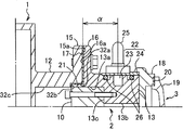
- the engine housing 12 and the motor housing 13 are the outer peripheral position in the radial direction of the stator 31 (stator core 10) and the engine side coupling surface 15a of the engine housing 12 and the motor housing 13. Are coupled to each other in a state where they are pressed in the axial direction over the entire circumference around the axis (axis parallel to the central axis O in FIG. 1). Specifically, the end of the engine housing 12 connected to the electric motor housing 13 protrudes in a bowl shape toward the outside in the radial direction from the other portions, and has an engine side flange 15 having an engine side connecting surface 15a. Is provided.
- an end of the motor housing 13 coupled to the engine housing 12 is provided with a motor-side flange 16 that protrudes in a bowl shape toward the outside in the radial direction from the other portions and has a motor-side coupling surface 16a. It has been.
- a heat insulating material 17 is sandwiched between the flanges 15 and 16. Specifically, the heat insulating material 17 is sandwiched between the flange side coupling surface 15a and the motor side coupling surface 16a.
- the flanges 15 and 16 are connected by bolts at a plurality of locations in the circumferential direction at the radially outer position of the stator 31 (stator core 10).
- the engine housing 12 and the motor housing 13 are coupled at the radially outer position of the stator 31 (stator core 10).
- the engine housing 12 is preferably formed of a magnetic material such as iron in order to ensure the required strength.
- the motor housing 13 is made of a magnetic material, the power generation efficiency may be reduced due to leakage of magnetic force.
- the motor housing 13 is preferably formed of a nonmagnetic material.
- the motor housing 13 is formed in a cylindrical shape as a whole.
- a large-diameter surface 13a, a small-diameter surface 13b having a diameter smaller than the diameter of the large-diameter surface 13a, and the large-diameter surface 13a and the small-diameter surface 13b are connected to the inner periphery of the motor housing 13 in a stepped manner.
- a connection surface 13c is formed between the large-diameter surface 13a and the small-diameter surface 13b (see FIG. 2).
- the motor housing 13 is provided with a projecting portion 21 that projects from the inner peripheral edge of the motor side coupling surface 16a toward the engine side in the axial direction over the entire circumference around the axis. That is, the overhang portion 21 is provided on the inner peripheral side of the end portion on the engine housing 12 side that is coupled to the engine housing 12. The overhang portion 21 protrudes from the motor side coupling surface 16a toward the engine housing 12 in the axial direction. Further, the overhanging portion 21 is provided in a ring shape over the entire circumference of the motor housing 13 with the center line O in FIG. 1 as the center.
- the overhanging portion 21 can be fitted inside the engine housing 12 in a state where the engine housing 12 and the electric motor housing 13 are arranged concentrically.
- the engine housing 12 has a fitting hole 32a into which the overhanging portion 21 can be fitted, and a small diameter hole 32c having a diameter smaller than that of the fitting hole 32a.
- a contact surface 32b interposed between the fitting hole 32a and the small diameter hole 32c is formed.
- an inner surface centering on the center line O of FIG. 1 is formed.
- the outer diameter dimension of the overhanging portion 21 and the inner diameter dimension of the fitting hole 32a are set to values that can be fitted to each other.
- the heat insulating material 17 is also provided between the outer surface of the overhang portion 21 and the inner surface of the fitting hole 32a. Therefore, the outer diameter dimension of the overhang portion 21 and the inner diameter dimension of the fitting hole 32a are set in consideration of the thickness dimension of the heat insulating material 17.
- the tip surface of the overhanging portion 21 is in contact with the contact surface 32b with the heat insulating material 17 interposed therebetween.
- the inner side surface of the overhang portion 21 is included in the large-diameter surface 13a.
- the large-diameter surface 13a is in surface contact with the outer peripheral surface of the stator core 10 in the entire width range in the axial direction of the stator 31 (direction parallel to the center line O in FIG. 1).
- the connection surface 13c is in surface contact with the side surface of the stator core 10 opposite to the engine 1 (hydraulic pump 3 side).
- the refrigerant passage 22 is provided in the motor housing 13 and is used for flowing a refrigerant (a liquid such as water or oil or a refrigerant gas) for cooling the stator 31.
- a refrigerant a liquid such as water or oil or a refrigerant gas
- the refrigerant passage 22 is disposed at a position offset to the motor-side coupling surface 16a, that is, the axially opposite side of the engine 1 (the hydraulic pump 3 side) with respect to the radially outer position of the stator. .
- symbol ⁇ indicates an offset amount from the motor side coupling surface 16 a of the refrigerant passage 22.
- the offset amount ⁇ is desirably as small as possible (the refrigerant passage 22 is disposed at a position close to the stator) in order to improve heat transfer efficiency.
- the refrigerant passage 22 is formed on the outer peripheral surface of the electric motor housing 13, extends in the circumferential direction and opens to the outer peripheral side of the electric motor housing 13, and the electric motor housing so as to cover the opening of the concave groove 23. 13 and the inner peripheral surface of the cover 24 provided on the outer peripheral surface.
- the recessed groove 23 and the cover 24 are respectively provided over the entire circumference of the motor housing 13.
- the pipe 25 is connected to the refrigerant passage 22.
- a pump (not shown)
- the refrigerant is supplied from the outside to the refrigerant passage 22 via the pipe 25 and returns from the refrigerant passage to the pump via the pipe 25. That is, the refrigerant circulates between the refrigerant passage 22 and the pump. It is preferable to provide a mechanism for cooling the refrigerant between the refrigerant passage 22 and the pump.
- reference numeral 26 denotes an O-ring that seals between the cover 24 and the motor housing 13. Each O-ring 26 is provided at a mounting portion of the cover 24.
- the engine housing 12 (engine-side coupling surface 15a) and the motor housing 13 (motor-side coupling surface 16a) are coupled at the radially outer position of the stator 31, and the refrigerant
- the passage 22 is disposed so as to be offset in the axial direction with respect to the stator 31 (the motor side coupling surface 16a).
- the motor housing 13 is further provided with a projecting portion 21 projecting toward the engine housing 12, and the inner peripheral surface of the motor housing 13 including the inner peripheral surface of the projecting portion 21 ( The large-diameter surface 13a) is in surface contact with the outer peripheral surface of the stator 31 (stator core 10). Therefore, the cooling efficiency can be improved by increasing the contact area (heat transfer area) between the stator 31 and the motor housing 13.
- the required cooling performance of the stator 31 (the generator motor 2) can be ensured without increasing the shaft length of the motor housing 13.
- the inner peripheral surface (large-diameter surface 13a) of the motor housing 13 including the inner peripheral surface of the overhanging portion 21 is in surface contact with the outer peripheral surface of the stator 31 (stator core 10) in the entire width range of the stator 31 in the axial direction.
- the connection surface 13c of the electric motor housing 13 is in surface contact with the side surface of the stator 31 opposite to the engine (the hydraulic pump 3 side). As a result, the heat transfer area can be further increased.
- the overhanging portion 21 for increasing the heat transfer area is fitted inside the engine housing 12 (the overhanging portion 21 is used as a fitting portion for the engine housing 12). Therefore, the concentricity between the engine housing 12 and the electric motor housing 13 can be ensured, and the assemblability can be improved.
- a refrigerant passage 22 is formed on the outer peripheral surface of the motor housing 13. Therefore, unlike the case where the refrigerant passage 22 is provided on the inner peripheral side of the electric motor housing 13, there is no possibility that the stator 31 and the rotor 30 are immersed in the refrigerant when the refrigerant leaks.
- the coolant passage 22 is constituted by the concave groove 23 formed in the motor housing 13 and the cover 24. Therefore, it is advantageous in terms of processing and cost as compared with the case where the independent refrigerant passage 22 is attached to the outer periphery of the motor housing 13.
- flanges 15 and 16 that project in a bowl shape toward the outside in the radial direction are provided, and the flanges 15 and 16 are coupled to each other. ing. Therefore, the flanges 15 and 16 for coupling the housings 12 and 13 can act as heat radiating fins that exchange heat with the outside air. Therefore, the cooling efficiency can be further improved by enhancing the heat dissipation of the engine housing 12 and the motor housing 13.
- Thermal insulation materials 17 and 20 are interposed between the engine housing 12 and the motor housing 13 (flanges 15 and 16) and between the motor housing 13 and the pump housing 14 (flanges 18 and 19), respectively. . Therefore, in the hybrid construction machine in which the engine 1, the generator motor 2 and the hydraulic pump 3 are connected in series, the heat transfer between the engine 1 and the generator motor 2 and the heat transfer between the generator motor 2 and the hydraulic pump 3 are performed. It can be suppressed by the heat insulating materials 17 and 20. Therefore, the cooling efficiency of the stator 31 by the refrigerant passage 22 can be increased by suppressing heat transfer from the engine 1 or the hydraulic pump 3 serving as a heat source to the motor housing 13 by the heat insulating materials 17 and 20.
- heat insulating materials 17 and 20 may be provided only between the engine housing 12 and the electric motor housing 13 or only between the electric motor housing 13 and the pump housing 14. Further, the heat insulating materials 17 and 20 can be omitted.
- the present invention is not limited to a hybrid excavator, but is a hybrid construction machine in which an engine, a generator motor, and a hydraulic pump are connected on the same axis, or an engine and a generator motor are connected on the same axis, and the hydraulic pump generates power. It can be widely applied to hybrid construction machines connected to the engine in parallel with the electric motor.
- the present invention is a hybrid construction machine, an engine having a crankshaft and an engine housing, a rotor connected to the crankshaft, a stator disposed at a radially outer position of the rotor, and the above
- a generator motor having a rotor and a motor housing that houses the stator, wherein the engine housing and the motor housing are connected to the engine side coupling surface of the engine housing and the motor housing at a radially outer position of the stator.
- the motor side coupling surface is coupled to each other, and the motor housing extends from the inner peripheral edge of the motor side coupling surface to the engine side in the axial direction over the entire circumference around the shaft and is fitted in the engine housing.
- the overhanging portion to be jammed and the coolant for cooling the stator are flowed.
- an inner peripheral surface of the motor housing including the inner peripheral surface of the projecting portion is in surface contact with the outer peripheral surface of the stator, and the refrigerant passage is in contact with the motor-side coupling surface.
- a hybrid construction machine arranged at a position shifted in the axial direction.
- the engine housing (engine side coupling surface) and the motor housing (motor side coupling surface) are coupled to each other at the radially outer position of the stator of the generator motor, and the refrigerant passage is the stator (motor side coupling surface).
- the motor housing is further provided with a projecting portion projecting toward the engine housing, and the inner peripheral surface of the motor housing including the inner peripheral surface of the projecting portion faces the outer peripheral surface of the stator. In contact. Therefore, the cooling efficiency can be improved by increasing the contact area (heat transfer area) between the stator and the motor housing.
- axis in the present invention means an axis parallel to the rotation axis of the crankshaft or the rotation axis of the rotor.
- the inner peripheral surface of the motor housing including the inner peripheral surface of the overhanging portion is in surface contact with the outer peripheral surface of the stator in the entire width range in the axial direction.
- the contact area can be maximized to increase heat transfer.
- full width range in the axial direction means the full width range in the axial direction of the stator coil.
- the inner peripheral surface of the motor housing contacts the outer peripheral surface of the coil.
- a large-diameter surface, a small-diameter surface having a diameter smaller than the diameter of the large-diameter surface, and the large-diameter surface and the small-diameter surface are connected in steps to the inner periphery of the motor housing.
- a connecting surface interposed between the large-diameter surface and the small-diameter surface is formed, and an inner peripheral surface of the projecting portion is included in the large-diameter surface, and the large-diameter surface is While the surface is in surface contact with the outer peripheral surface, the connection surface is preferably in surface contact with the side surface of the stator opposite to the engine.
- the electric motor housing can be brought into surface contact with the side surface of the stator. Therefore, the heat transfer area between the motor housing and the stator can be further increased.
- the projecting portion of the motor housing can be fitted inside the engine housing in a state where the engine housing and the motor housing are arranged concentrically.
- the overhanging portion for increasing the heat transfer area can be used as a fitting portion for the engine housing.
- the refrigerant passage is formed on the outer peripheral surface of the electric motor housing, extends in the circumferential direction and opens to the outer peripheral side of the electric motor housing, and the electric motor so as to cover the opening of the concave groove. It is preferable that it is prescribed
- the refrigerant passage is formed on the outer peripheral surface of the motor housing. Therefore, unlike the case where the refrigerant passage is provided on the inner peripheral side of the motor housing, there is no possibility that the stator or the rotor is immersed in the refrigerant when the refrigerant leaks.
- the refrigerant passage is constituted by the concave groove formed in the motor housing and the cover. Therefore, it is advantageous in terms of processing and cost compared to the case where an independent refrigerant passage is attached to the outer periphery of the housing.
- an end of the engine housing that is coupled to the motor housing is provided with an engine-side flange that protrudes radially outward from the other portions and has the engine-side coupling surface.
- An end of the electric motor housing that is coupled to the engine housing is provided with an electric motor side flange that protrudes radially outward from the other portions and has the electric motor side coupling surface, and the engine side flange and the electric motor. It is preferable that the side flange is connected.
- the engine-side flange and the motor-side flange for coupling the engine housing and the motor housing can act as heat radiating fins that exchange heat with the outside air. Therefore, the cooling efficiency can be further improved by enhancing the heat dissipation in the engine housing and the motor housing.
- a hydraulic pump having a pump housing coupled to the opposite side of the motor housing to the engine, and interposed between at least one of the engine housing and the motor housing and between the motor housing and the pump housing. It is preferable to further include a heat insulating material.
- the heat transfer between the engine and the generator motor and the heat transfer between the generator motor and the hydraulic pump are performed by the heat insulating material. Can be suppressed. Therefore, the cooling efficiency of the stator by the refrigerant passage can be increased by suppressing heat transfer from the engine and / or hydraulic pump serving as a heat source to the motor housing by the heat insulating material.
- a heat insulating material is sandwiched between the engine side coupling surface and the motor side coupling surface.
- heat transfer from the engine to the motor housing can be suppressed by the heat insulating material.
Landscapes
- Engineering & Computer Science (AREA)
- Power Engineering (AREA)
- Mining & Mineral Resources (AREA)
- Civil Engineering (AREA)
- General Engineering & Computer Science (AREA)
- Structural Engineering (AREA)
- Hybrid Electric Vehicles (AREA)
- Motor Or Generator Frames (AREA)
- Motor Or Generator Cooling System (AREA)
- Component Parts Of Construction Machinery (AREA)
- Connection Of Motors, Electrical Generators, Mechanical Devices, And The Like (AREA)
- Operation Control Of Excavators (AREA)
Abstract
L'invention porte sur un engin de chantier hybride. Un moteur générateur de la présente invention est efficacement refroidi tout en supprimant la longueur hors tout d'une unité de puissance. Un carter moteur (13) porte : une section formant bourrelet (21) qui fait saillie vers l'extérieur, sur toute la circonférence qui entoure son axe, d'un bord intérieur d'une face de liaison côté moteur (16a) vers un côté moteur (1) dans la direction axiale et qui s'ajuste dans un carter de moteur (12) ; et un trajet de refroidissement (22) qui conduit le fluide de refroidissement destiné au refroidissement d'un stator (31). La face circonférentielle intérieure du carter de moteur (13), qui comprend la face circonférentielle intérieure de la section formant bourrelet (21) entre en contact superficiel avec la face circonférentielle extérieure du stator (31), et le trajet de refroidissement (22) est disposé dans une position écartée dans la direction axiale de la face de liaison côté moteur (16a).
Priority Applications (3)
| Application Number | Priority Date | Filing Date | Title |
|---|---|---|---|
| US14/111,339 US9337697B2 (en) | 2011-04-12 | 2012-04-11 | Hybrid construction machine |
| EP12771542.3A EP2698903A4 (fr) | 2011-04-12 | 2012-04-11 | Engin de chantier hybride |
| CN201280017933.0A CN103460563B (zh) | 2011-04-12 | 2012-04-11 | 混合动力工程机械 |
Applications Claiming Priority (2)
| Application Number | Priority Date | Filing Date | Title |
|---|---|---|---|
| JP2011-088013 | 2011-04-12 | ||
| JP2011088013A JP5626085B2 (ja) | 2011-04-12 | 2011-04-12 | ハイブリッド建設機械 |
Publications (1)
| Publication Number | Publication Date |
|---|---|
| WO2012140879A1 true WO2012140879A1 (fr) | 2012-10-18 |
Family
ID=47009070
Family Applications (1)
| Application Number | Title | Priority Date | Filing Date |
|---|---|---|---|
| PCT/JP2012/002507 Ceased WO2012140879A1 (fr) | 2011-04-12 | 2012-04-11 | Engin de chantier hybride |
Country Status (5)
| Country | Link |
|---|---|
| US (1) | US9337697B2 (fr) |
| EP (1) | EP2698903A4 (fr) |
| JP (1) | JP5626085B2 (fr) |
| CN (1) | CN103460563B (fr) |
| WO (1) | WO2012140879A1 (fr) |
Families Citing this family (4)
| Publication number | Priority date | Publication date | Assignee | Title |
|---|---|---|---|---|
| JP5972821B2 (ja) * | 2013-03-29 | 2016-08-17 | 株式会社小松製作所 | 発電機モータへのディーゼル酸化触媒装置搭載構造 |
| US10562388B2 (en) | 2014-06-16 | 2020-02-18 | Kubota Corporation | Parallel hybrid power transmission mechanism |
| JP6526551B2 (ja) * | 2015-12-11 | 2019-06-05 | 株式会社クボタ | パラレルハイブリッド動力伝達機構 |
| KR200499160Y1 (ko) * | 2023-03-17 | 2025-05-15 | 주식회사 신강전기 | 모터 커버 |
Citations (2)
| Publication number | Priority date | Publication date | Assignee | Title |
|---|---|---|---|---|
| JPH0993871A (ja) * | 1995-09-22 | 1997-04-04 | Denso Corp | 回転電機 |
| JP2007181273A (ja) | 2005-12-27 | 2007-07-12 | Shin Caterpillar Mitsubishi Ltd | ポンプ装置 |
Family Cites Families (15)
| Publication number | Priority date | Publication date | Assignee | Title |
|---|---|---|---|---|
| CN1055576C (zh) * | 1994-06-08 | 2000-08-16 | 精密电力设备公司 | 多用途交流电动发电机 |
| DE4421427C1 (de) * | 1994-06-18 | 1996-01-18 | Fichtel & Sachs Ag | Elektromotor-Getriebe-Baueinheit |
| JP3168895B2 (ja) * | 1995-12-06 | 2001-05-21 | トヨタ自動車株式会社 | ハイブリッド駆動装置 |
| US5711740A (en) | 1996-05-29 | 1998-01-27 | New Venture Gear, Inc. | Mechanical clutch for planetary-type gear reduction unit |
| DE19817333C5 (de) * | 1998-04-18 | 2007-04-26 | Conti Temic Microelectronic Gmbh | Elektrische Antriebseinheit aus Elektromotor und Elektronikmodul |
| US6253437B1 (en) * | 1999-03-03 | 2001-07-03 | Ford Global Technologies, Inc. | Hybrid vehicle motor alignment |
| DE19916459A1 (de) * | 1999-04-12 | 2000-10-26 | Bosch Gmbh Robert | Starter-Generator für ein Kraftfahrzeug |
| JP2001339924A (ja) * | 2000-05-30 | 2001-12-07 | Honda Motor Co Ltd | アウターロータ型モータ・ジェネレータ |
| DE10243535A1 (de) * | 2001-09-26 | 2003-04-24 | Luk Lamellen & Kupplungsbau | Getriebe |
| US7489114B2 (en) * | 2004-11-19 | 2009-02-10 | Aisin Aw Co., Ltd. | Hybrid vehicle drive unit |
| EP2595286A3 (fr) | 2005-05-10 | 2016-04-06 | Komatsu Ltd. | Moteur avec générateur comme unité de puissance auxiliaire |
| JP2009298369A (ja) * | 2008-06-17 | 2009-12-24 | Mazda Motor Corp | 車両の駆動装置 |
| JP5206457B2 (ja) | 2009-02-03 | 2013-06-12 | コベルコ建機株式会社 | ハイブリッド作業機械の軸潤滑装置 |
| US20110006545A1 (en) * | 2009-07-08 | 2011-01-13 | Hamilton Sundstrand Corporation | Nested exciter and main generator stages for a wound field generator |
| CN201629633U (zh) | 2010-02-02 | 2010-11-10 | 株洲南车时代电气股份有限公司 | 一种与发动机连接成一体的永磁发电机 |
-
2011
- 2011-04-12 JP JP2011088013A patent/JP5626085B2/ja not_active Expired - Fee Related
-
2012
- 2012-04-11 CN CN201280017933.0A patent/CN103460563B/zh not_active Expired - Fee Related
- 2012-04-11 EP EP12771542.3A patent/EP2698903A4/fr not_active Withdrawn
- 2012-04-11 US US14/111,339 patent/US9337697B2/en not_active Expired - Fee Related
- 2012-04-11 WO PCT/JP2012/002507 patent/WO2012140879A1/fr not_active Ceased
Patent Citations (2)
| Publication number | Priority date | Publication date | Assignee | Title |
|---|---|---|---|---|
| JPH0993871A (ja) * | 1995-09-22 | 1997-04-04 | Denso Corp | 回転電機 |
| JP2007181273A (ja) | 2005-12-27 | 2007-07-12 | Shin Caterpillar Mitsubishi Ltd | ポンプ装置 |
Non-Patent Citations (1)
| Title |
|---|
| See also references of EP2698903A4 |
Also Published As
| Publication number | Publication date |
|---|---|
| CN103460563B (zh) | 2016-04-13 |
| JP5626085B2 (ja) | 2014-11-19 |
| CN103460563A (zh) | 2013-12-18 |
| EP2698903A4 (fr) | 2016-06-01 |
| US20140026551A1 (en) | 2014-01-30 |
| EP2698903A1 (fr) | 2014-02-19 |
| JP2012223003A (ja) | 2012-11-12 |
| US9337697B2 (en) | 2016-05-10 |
Similar Documents
| Publication | Publication Date | Title |
|---|---|---|
| JP5908741B2 (ja) | 回転電機 | |
| JP6318056B2 (ja) | 回転電機のハウジング、およびこれを備えた回転電機 | |
| JP5718391B2 (ja) | 回転電機 | |
| JP4082359B2 (ja) | 回転電機の冷却構造 | |
| JP7106892B2 (ja) | 回転電機 | |
| CN110571976B (zh) | 一种发动机和电机总成 | |
| JP6056518B2 (ja) | 回転電機用回転構造 | |
| US20200106341A1 (en) | Rotating electric machine | |
| JP5231059B2 (ja) | 油圧ポンプユニット | |
| US10666111B2 (en) | Rotary electric machine | |
| CN110224552B (zh) | 一种双重冷却的电机结构 | |
| WO2021051795A1 (fr) | Ensemble moteur et moteur électrique | |
| CN110350679B (zh) | 一种定子密封结构及具有该密封结构的电机 | |
| CN103907270A (zh) | 用于电机的壳体结构 | |
| JP2013132116A (ja) | 回転電機 | |
| CN111600419B (zh) | 旋转电机 | |
| WO2012140879A1 (fr) | Engin de chantier hybride | |
| CN115864768A (zh) | 双转子轮毂电机 | |
| JP4895118B2 (ja) | モータ | |
| JP2009219186A (ja) | ロータ冷却構造 | |
| JPWO2019159240A1 (ja) | 回転電機 | |
| JP2013132115A (ja) | 回転電機 | |
| JP2013051805A (ja) | 回転電機の冷却構造 | |
| CN211063482U (zh) | 一种发动机和电机总成 | |
| KR20100011738A (ko) | 하이브리드 차량용 구동모터의 고정자 조립구조 |
Legal Events
| Date | Code | Title | Description |
|---|---|---|---|
| 121 | Ep: the epo has been informed by wipo that ep was designated in this application |
Ref document number: 12771542 Country of ref document: EP Kind code of ref document: A1 |
|
| WWE | Wipo information: entry into national phase |
Ref document number: 14111339 Country of ref document: US |
|
| NENP | Non-entry into the national phase |
Ref country code: DE |
|
| REEP | Request for entry into the european phase |
Ref document number: 2012771542 Country of ref document: EP |
|
| WWE | Wipo information: entry into national phase |
Ref document number: 2012771542 Country of ref document: EP |