WO2012140914A1 - プリンタ - Google Patents
プリンタ Download PDFInfo
- Publication number
- WO2012140914A1 WO2012140914A1 PCT/JP2012/002595 JP2012002595W WO2012140914A1 WO 2012140914 A1 WO2012140914 A1 WO 2012140914A1 JP 2012002595 W JP2012002595 W JP 2012002595W WO 2012140914 A1 WO2012140914 A1 WO 2012140914A1
- Authority
- WO
- WIPO (PCT)
- Prior art keywords
- label
- printed
- printing
- paper
- Prior art date
- Legal status (The legal status is an assumption and is not a legal conclusion. Google has not performed a legal analysis and makes no representation as to the accuracy of the status listed.)
- Ceased
Links
Images


Classifications
-
- G—PHYSICS
- G06—COMPUTING OR CALCULATING; COUNTING
- G06K—GRAPHICAL DATA READING; PRESENTATION OF DATA; RECORD CARRIERS; HANDLING RECORD CARRIERS
- G06K15/00—Arrangements for producing a permanent visual presentation of the output data, e.g. computer output printers
- G06K15/02—Arrangements for producing a permanent visual presentation of the output data, e.g. computer output printers using printers
- G06K15/18—Conditioning data for presenting it to the physical printing elements
- G06K15/1867—Post-processing of the composed and rasterized print image
-
- B—PERFORMING OPERATIONS; TRANSPORTING
- B41—PRINTING; LINING MACHINES; TYPEWRITERS; STAMPS
- B41J—TYPEWRITERS; SELECTIVE PRINTING MECHANISMS, i.e. MECHANISMS PRINTING OTHERWISE THAN FROM A FORME; CORRECTION OF TYPOGRAPHICAL ERRORS
- B41J3/00—Typewriters or selective printing or marking mechanisms characterised by the purpose for which they are constructed
- B41J3/01—Typewriters or selective printing or marking mechanisms characterised by the purpose for which they are constructed for special character, e.g. for Chinese characters or barcodes
-
- B—PERFORMING OPERATIONS; TRANSPORTING
- B41—PRINTING; LINING MACHINES; TYPEWRITERS; STAMPS
- B41J—TYPEWRITERS; SELECTIVE PRINTING MECHANISMS, i.e. MECHANISMS PRINTING OTHERWISE THAN FROM A FORME; CORRECTION OF TYPOGRAPHICAL ERRORS
- B41J11/00—Devices or arrangements of selective printing mechanisms, e.g. ink-jet printers or thermal printers, for supporting or handling copy material in sheet or web form
- B41J11/36—Blanking or long feeds; Feeding to a particular line, e.g. by rotation of platen or feed roller
- B41J11/42—Controlling printing material conveyance for accurate alignment of the printing material with the printhead; Print registering
-
- B—PERFORMING OPERATIONS; TRANSPORTING
- B41—PRINTING; LINING MACHINES; TYPEWRITERS; STAMPS
- B41J—TYPEWRITERS; SELECTIVE PRINTING MECHANISMS, i.e. MECHANISMS PRINTING OTHERWISE THAN FROM A FORME; CORRECTION OF TYPOGRAPHICAL ERRORS
- B41J3/00—Typewriters or selective printing or marking mechanisms characterised by the purpose for which they are constructed
- B41J3/407—Typewriters or selective printing or marking mechanisms characterised by the purpose for which they are constructed for marking on special material
- B41J3/4075—Tape printers; Label printers
-
- G—PHYSICS
- G06—COMPUTING OR CALCULATING; COUNTING
- G06K—GRAPHICAL DATA READING; PRESENTATION OF DATA; RECORD CARRIERS; HANDLING RECORD CARRIERS
- G06K1/00—Methods or arrangements for marking the record carrier in digital fashion
- G06K1/12—Methods or arrangements for marking the record carrier in digital fashion otherwise than by punching
- G06K1/121—Methods or arrangements for marking the record carrier in digital fashion otherwise than by punching by printing code marks
-
- G—PHYSICS
- G06—COMPUTING OR CALCULATING; COUNTING
- G06K—GRAPHICAL DATA READING; PRESENTATION OF DATA; RECORD CARRIERS; HANDLING RECORD CARRIERS
- G06K15/00—Arrangements for producing a permanent visual presentation of the output data, e.g. computer output printers
- G06K15/02—Arrangements for producing a permanent visual presentation of the output data, e.g. computer output printers using printers
- G06K15/021—Adaptations for printing on specific media
- G06K15/024—Adaptations for printing on specific media for printing on segmented surfaces, e.g. sticker sheets, label rolls
-
- G—PHYSICS
- G06—COMPUTING OR CALCULATING; COUNTING
- G06K—GRAPHICAL DATA READING; PRESENTATION OF DATA; RECORD CARRIERS; HANDLING RECORD CARRIERS
- G06K15/00—Arrangements for producing a permanent visual presentation of the output data, e.g. computer output printers
- G06K15/02—Arrangements for producing a permanent visual presentation of the output data, e.g. computer output printers using printers
- G06K15/16—Means for paper feeding or form feeding
-
- G—PHYSICS
- G06—COMPUTING OR CALCULATING; COUNTING
- G06K—GRAPHICAL DATA READING; PRESENTATION OF DATA; RECORD CARRIERS; HANDLING RECORD CARRIERS
- G06K5/00—Methods or arrangements for verifying the correctness of markings on a record carrier; Column detection devices
Definitions
- the present invention relates to a label printer or the like in which a printed label is cut out from a sheet while printing is performed on each label in a process in which the sheet temporarily attached to the mount is moved at equal intervals.
- the present invention relates to a printer that prints in each print area while a sheet in which areas are arranged at equal intervals moves a sheet sequentially in the arrangement direction of the print area.
- a label printer described in Patent Document 1 is known.
- a print head (specifically, a thermal head) prints characters according to print data for each label that passes through the print position in the process of moving the paper on which the labels are temporarily attached to the mount. And print marks and marks.
- the first printed label and the next label are printed.
- the boundary portion reaches the cut position, the paper is stopped and printing for the next label is interrupted, the boundary portion of the paper is cut, and the first printed label is cut out. Thereafter, the feeding of the paper is resumed, and the printing for the label on which printing has been suspended is resumed.
- the paper movement continues without printing the next label that passes the print position.
- the sheet is stopped, the boundary of the sheet is cut, and the first printed label is cut out. Thereafter, the sheet is moved (retracted) in the reverse direction so that the leading end of the next label (new leading label) is at the printing position. Then, the next label is printed again while moving the paper in the normal direction. Thereafter, similarly, printing for each label is performed while repeating printing on the label, cutting the paper, and moving the paper in the reverse direction.
- the information to be printed includes a barcode, as described above, when printing for the label is completed, the paper is moved to the cutting position without printing for the next label, and the paper is cut. Later, the paper is returned and the next label is printed. In this manner, since printing is not performed on the next label until each printed label is cut out from the sheet, it is possible to reliably prevent white spots in the barcode.
- the paper when the information to be printed does not include a barcode, the paper can be printed at a higher speed without moving in the reverse direction, and the information to be printed. If the barcode is included in the information, the information can be printed surely.
- QR code M as shown in FIG. 1A is included as information to be printed on the label (print area).
- the QR code M has a structure in which finder patterns (cutout symbols) FD1, FD2, and FD3 are arranged at three corners of a square data area. Data is recorded on the QR code M having such a structure with redundancy, and error correction is possible when data is read from the QR code (M). Therefore, even when a part of the QR code (M) is contaminated or damaged and accurate data cannot be read out, normal data can be restored by error correction.
- the QR code M can be restored even if it is partially dirty or damaged (white). Therefore, when the QR code M is printed on each label, the above-described barcode is printed. In this way, the printing for the label is completed, the label is cut out from the paper, the paper is not returned, and the printing for the next label is not performed. Can be cut. Accordingly, it is possible to perform label printing at a higher speed.
- the QR code M may not be able to be restored if the two finder patterns FD1 and FD2 have white spots WL at the same time. For this reason, as described above, if the paper is always cut sequentially while repeatedly feeding and interrupting and resuming printing, data may not be restored from the printed QR code.
- the present invention has been made in view of such circumstances, and a printer capable of printing a QR code at a higher speed in a state in which data can always be restored to each print area sequentially arranged on a sheet. It is to provide.
- the printer according to the present invention is a printer that performs printing on each print area in accordance with print data representing information to be printed while sequentially moving paper in which print areas are arranged at predetermined intervals in the arrangement direction of the print area.
- Printing operation control means for controlling the printing operation so as to stop the movement of the paper to interrupt the printing on the print area and then resume the movement of the paper and the printing on the printing area; and the print data
- both of the two finder patterns arranged on one side of the QR code in the print area where the print is interrupted are both When the paper movement is stopped,
- the determination means for determining whether or not both of the two finder patterns arranged on one side of the QR code in the print area where the printing is interrupted are printed by the determination means when the movement of the paper is stopped.
- a print operation correction control means for controlling the print operation so that both of the two finder patterns of the QR code do not become the positions to be printed at the same time. . *
- the printer according to the present invention can be configured to perform printing on each label as a print area in accordance with the print data, and to sequentially cut out printed labels from the paper.
- the printing operation control means stops the movement of the paper when the boundary between the first printed label and the next label reaches the cut position, and interrupts printing on the label, The border is cut and the first printed label is cut out from the paper, and then the printing operation is controlled so as to resume the movement of the paper and the printing on the label.
- the printing operation correction control means can control the printing operation so as to change the direction of the QR code.
- the direction of the QR code is changed so that both of the two finder patterns arranged on one side of the QR code are not at the same position to be printed, and printing is performed on each print area. Even if a white spot occurs in the print portion of the label due to the movement of the image and the interruption or resumption of printing, the white spot does not affect both of the two finder patterns arranged on one side of the QR code. In particular, by changing the direction of the QR code, both the two finder patterns arranged on one side of the QR code do not have to be printed at the same time without largely changing the print position of the QR code in each print area. can do. *
- the printing operation correction control unit may control the printing operation so that the QR code is rotated by 90 °.
- the QR code is printed on each print area while being rotated by 90 ° so that both of the two finder patterns arranged on one side of the QR code are not at positions to be printed at the same time. Even if white spots occur in the print portion of the print area due to the movement of the paper and the interruption or resumption of printing, the white spots do not affect both of the two finder patterns arranged on one side of the QR code. In particular, by rotating the QR code having a square shape by 90 °, both the two finder patterns arranged on one side of the QR code do not become positions to be printed at the same time without largely changing the apparent print state. can do. *
- the print operation correction control means includes a print data correction means for correcting the print data so that both of the two finder patterns are not at positions to be printed simultaneously. can do.
- the print data is corrected so that both of the two finder patterns arranged on one side of the QR code are not at the positions to be printed at the same time.
- the two viewfinders where the white spots are arranged on one side of the QR code. It doesn't affect both patterns.
- the printing operation is performed so as to stop the movement of the paper and interrupt the printing on the print area, and then resume the movement of the paper and the printing on the printing area.
- Each print area can be continuously printed while being moved in one direction without being moved in the reverse direction.
- the white spots do not affect both of the two finder patterns arranged on one side of the QR code. Therefore, it is possible to prevent a situation where data cannot be restored from the QR code printed on each label. Therefore, the QR code can be printed at a higher speed for each label sequentially arranged on the paper in a state where the data can always be restored.
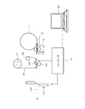
- FIG. 6 is a diagram illustrating a printer (label printer) according to an embodiment of the present invention.
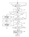
- 6 is a flowchart showing a flow (No. 1) of processing of a printing operation.
- 6 is a flowchart showing a flow (2) of a printing operation process.
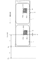
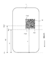
- FIG. 6 is a diagram illustrating a relationship example between a print start position Pps of a QR code finder pattern in a label (print area), a cut position Pp for cutting a sheet, and a print position Pp by a thermal head.
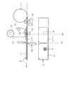
- FIG. 3 is a diagram illustrating a state in which a sheet is cut at a boundary portion between a first printed label and a next label in the label printer illustrated in FIG. 2.
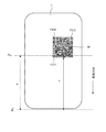
- FIG. 5 is a diagram illustrating an example in which two finder patterns arranged on one side of a QR code do not simultaneously become print positions.
- FIG. 5 is a diagram without closing an example in which the QR code is rotated by 90 ° so that two finder patterns arranged on one side of the QR code are not in the print position at the same time.
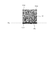
- FIG. 8 is a diagram illustrating an example in which white spots are applied to the QR code illustrated in FIG. 7. It is a figure which shows the other relationship example of the print start position of the QR Code finder pattern in a label, the cut position which cuts a paper, and the print position Pp by a thermal head.
- a printer (label printer) according to an embodiment of the present invention is configured as shown in FIG. *
- a sheet S in which labels (print areas) are temporarily attached to a mount with a predetermined width at a predetermined interval is wound around a roll 11, and the sheet S fed from the roll 11 by a feed roller 12 is transported 100.
- This label printer is a thermal transfer printer.
- a thermal head 23 is disposed at a predetermined position on the conveyance path 100 and a platen roller 24 is disposed so as to face the thermal head 23.
- the ink ribbon 20 is wound between the feed roller 21 and the take-up roller 22, and the ink ribbon 20 fed from the feed roller 21 is taken up by the take-up roller 22 via a plurality of tension rollers. .
- the ink ribbon 20 and the sheet S moving on the transport path 100 overlap each other and pass between the thermal head 23 and the platen roller 24.
- a paper position sensor 13 for detecting the leading edge of the paper S fed from the roll 11 is provided at a predetermined position near the feeding roller 12.
- a cutter 14 for cutting the paper S is provided at a predetermined position downstream from the position (printing position) of the thermal head 23 in the moving direction of the paper S.
- the label printer has a controller 10 that controls the printing operation.
- the controller 10 applies the information necessary for printing (print information) such as the detection signal from the paper position detection sensor 13, the print data from the host device 30 such as a personal computer, and format data (print information) to the paper S of the ink ribbon 20.
- Print information information necessary for printing
- the host device 30 such as a personal computer
- format data print information
- Control related to the printing operation for each label (print region) of the paper S such as drive control of the thermal head 23 that performs thermal transfer of the paper, feed control of the paper S, and drive control of the cutter 14 is performed.
- the information represented by the print data is printed on a predetermined area of each label of the paper S moving on the transport path 100 by the printing operation controlled by the controller 10, and the paper S is cut and a printed label is printed. Cut out from the paper S.
- the controller 10 performs processing related to the printing operation according to the procedure shown in FIGS. *
- the sheet S fed from the roll 11 by the feed roller 12 is set at a position (initial position) where the leading end is detected by the sheet position sensor 13 as shown in FIG. .
- the controller 10 prints print data representing information to be printed together with a print request from the host device 30 (personal computer), format data representing a print format (position and shape of information to be printed, label, etc.), and the like. Is acquired (S11), print data is extracted from the print information, and the print data is set in a predetermined memory (S12). Thereafter, the controller 10 sets the print data in a predetermined direction with respect to the label (for example, as shown in FIG.
- the two finder patterns FD1 and FD2 on one side are on the most downstream side in the moving direction of the paper S). Whether or not data representing a QR code to be printed is included (in a direction in which the two finder patterns FD2 and FD3 on the other side are aligned in parallel with the moving direction of the paper S). Is determined (S13). *
- the controller 10 When the print data includes data representing a QR code to be printed in a predetermined direction with respect to the label (YES in S13), the controller 10 further prints the print data, format data, thermal head 23, When printing according to the print data on each label of the paper S based on the information related to the position of the cutter 14, as shown in FIG. 6, the boundary between the first printed label Ln and the next label Ln + 1 When the position reaches the cut position Pc (position at which the cutter 14 is disposed), both the finder patterns FD1 and FD2 (see FIG.
- the distance X1 between the cut position Pc and the print position Pp1 is from the leading edge (cut position) of the paper S.
- the distance between the finder patterns FD1 and FD2 of the QR code M is smaller than the distance Y, when the boundary between the first printed label Ln and the next label Ln + 1 reaches the cut position Pc, the QR code M at the next label Ln + 1
- Both the finder patterns FD1 and FD2 (see FIG. 5) arranged on one side do not reach the position Pp1 to be printed.
- the distance X2 between the cut position Pc and the print position Pp2 is the distance Y from the leading edge (cut position) of the paper S to the finder patterns FD1 and FD2 of the QR code M and the paper of each finder pattern FD1 and FD2. If it is larger than the sum of the widths Z in the moving direction (Y + Z), one side of the QR code M at the next label Ln + 1 when the boundary between the first printed label Ln and the next label Ln + 1 reaches the cut position Pc. Both of the finder patterns FD1 and FD2 (see FIG. 5) lined up in line have already passed the position Pp2 to be printed. *
- the controller 10 corrects the print data so that the QR code M is rotated 90 ° to the right to change its orientation.
- S15 the two finder patterns of the QR code M at the next label Ln + 1 become the positions Pp to be printed simultaneously. As shown in FIG. 8, only the finder pattern FD1 is the position Pp to be printed. *
- the set print data does not include a QR code (NO in S13), or if the print data includes a QR code (YES in S13), the first printed label Ln and the next printed label Ln When the boundary with the label Ln + 1 reaches the cut position Pc, the two finder patterns (for example, FD1 and FD2) arranged on one side of the QR code M in the next label Ln + 1 are not at the position Pp to be printed. In this case (NO in S14: see FIG. 7), the set print data is not corrected. *
- the controller 10 detects the leading edge by the paper position sensor 13 as shown in FIG.
- the conveyance control of the sheet S being started is started (S16).
- the sheet S starts to move on the conveyance path 100 at a predetermined speed.
- the controller 10 proceeds to the process shown in FIG. 4 and monitors whether or not the print start timing for the leading label of the sheet S has come (S17). Whether or not the print start timing has come is determined based on, for example, the position at which label printing should start based on the feed amount of the paper S, format data (label size, print start position within the label, etc.), etc. It can be determined by whether or not Pp (the position of the thermal head 23) has been reached. If the controller 10 determines that the print start timing for the leading label of the paper S has come (YES in S17), it starts driving control of the thermal head 23 based on the print data set as described above (S18). As a result, information (characters, marks, QR code M, etc.) based on the print data is printed on the leading label of the moving paper S. *
- the controller 10 determines whether or not the boundary between the first label and the next label has reached the cut position Pc (S19), and the print end timing for the first label. (S20) is monitored. When the print end timing for the first label comes (YES in S20), the controller 10 stops the drive control of the thermal head 23 and ends the print (S21). Thereafter, the controller 10 determines whether or not printing has been completed for all the specified number of labels (S22). If not (NO in S22), has the print start timing for the next label been reached? Whether or not is monitored (S17). When the print start timing for the next label comes (YES in S17), the controller 10 starts driving control of the thermal head 23 based on the set print data (S18), and printing for the next label is started. *
- the controller 10 determines whether or not the boundary between the first printed label and the next label has reached the cut position Pc (S19), and further prints for the next label. It is monitored whether or not it is the end timing (S20). In the process, when the boundary between the first printed label and the next label being printed reaches the cut position Pc (YES in S19), the controller 10 stops the conveyance of the paper S and interrupts the printing ( S23). Then, the controller 10 controls the cutter 14 to cut the paper S (S24). As a result, the first printed label is cut out from the paper S. Thereafter, the controller 10 resumes transport of the paper S and resumes printing for the next label (S25).
- the controller 10 determines whether or not the boundary between the label being printed and the next label has reached the cut position Pc (S19), and whether or not the print end timing has been reached for the label being printed (S20). ) Resume monitoring.
- the controller 10 stops the drive control of the thermal head 23 and ends the print (S21).
- the controller 10 repeatedly executes the same processing (S17 to S25) until printing for all the designated number of labels is completed (S22).
- S18 ⁇ S21 when printing is performed on each label of the moving paper S (S18 ⁇ S21), when the boundary between the first printed label and the next label being printed reaches the cut position Pc (S19).
- the controller 10 When printing is completed for all the specified number of labels (YES in S22), the controller 10 performs a cut process for the last printed label (S26). By this process, the paper S is moved without printing on the next label until the final printed label at the end reaches the cut position Pc. When the boundary between the first printed label and the next label reaches the cutting position Pc, the paper S is cut by the cutter 14 and the final printed label is cut out from the paper S.
- the boundary between the first printed label and the next label being printed reaches the cut position Pc.
- the movement of the paper S is stopped, the printing for the next label is interrupted (see S23), the boundary is cut (see S24), and the first printed label is cut out from the paper S.
- the movement of the sheet S and the printing for the next label are resumed (see S25), so that the sheet S is returned to the print position Pp after the printed label is cut out from the sheet S.
- both the two finder marks FD1 and FD2 arranged on one side of the QR code M become the print position Pp.
- the print data is corrected so that the QR code M is rotated 90 ° to the right (see FIG. 8).
- the white spot WL is applied only to the finder pattern FD1 of the QR code M as shown in FIG.
- the QR code M can be printed at a higher speed for each label sequentially arranged on the paper S in a state where data can always be restored.
- the two finder patterns FD1 and FD2 do not come to Pp at the printing position at the same time by rotating the square QR code M by 90 °, the appearance of the printed QR code M changes greatly. (See FIGS. 7 and 8). Note that the method for preventing the two finder patterns FD1 and FD2 from simultaneously reaching the print position at Pp is not limited to this, and the QR code M can be rotated at an arbitrary angle or moved forward, backward, left, or right. You may do it. *
- two finder patterns FD1 and FD2 on one side are arranged at the most downstream side in the moving direction of the sheet S and orthogonal to the moving direction, and two finder patterns on the other side.
- the print data includes data representing the QR code M to be printed in the direction in which the patterns FD2 and FD3 are arranged in parallel with the moving direction of the paper S.
- the present invention is not limited to this.
- two finder patterns FD2 and FD3 on one side are arranged on the most upstream side in the moving direction of the sheet S and orthogonal to the moving direction.
- the print data includes data representing the QR code M to be printed in the direction in which the two finder patterns FD1 and FD2 on one side are aligned in parallel with the moving direction of the paper S
- the same print as described above It is also possible to perform the operation.
- the distance X between the cut position Pc and the print position Pp the distance Y from the head of the paper S (the cut position Pc of the paper S) to the two finder patterns FD2 and FD3, and the finder patterns FD2 and FD3
- the QR code M may be rotated 90 ° to the left (see the state shown in FIG. 7).
- the printing operation is controlled so as to interrupt printing, cut the boundary portion, cut out the first printed label Ln from the paper, and then resume the movement of the paper S and printing on the label Ln.
- the printing operation is not particularly limited as long as the movement of the paper is stopped for some reason, the printing on the label is interrupted, and then the movement of the paper and the printing on the label are resumed.
- the movement of the paper S is stopped and the printing on the label Ln + 1 is interrupted, and the printed label Ln is peeled off from the mount to form a predetermined object.
- the printing operation may be controlled so that the movement of the sheet S and the printing on the label Ln are resumed.
- the paper S in which the print areas are arranged in addition to the paper in which the label is temporarily attached to the mount as described above, the paper in which tags having strips and holes formed at equal intervals are arranged as the print area, In addition, it is possible to use a sheet on which labels without a mount are arranged as a print area.
- the label printer according to the present invention is not limited to a thermal printer, and may be another type of printer.
- the label printer according to the present invention has an effect that the QR code can be printed at a higher speed in a state where data can always be restored for each label sequentially arranged on the paper.
- it is useful as a label printer in which printed labels are cut out from the paper while printing is performed on each label in the process of moving the paper on which the labels are temporarily attached to the mount.
- Controller 11 Roll 12 Feeding roller 13 Paper position sensor 14 Cutter 20 Ink ribbon 21 Feeding roller 22 Winding roller 23 Thermal head (print head) 24 Platen roller 30 Host device (personal computer) 100 Conveyance path
Landscapes
- Engineering & Computer Science (AREA)
- Physics & Mathematics (AREA)
- General Physics & Mathematics (AREA)
- Theoretical Computer Science (AREA)
- General Engineering & Computer Science (AREA)
- Record Information Processing For Printing (AREA)
- Printers Characterized By Their Purpose (AREA)
- Accessory Devices And Overall Control Thereof (AREA)
- Handling Of Sheets (AREA)
Abstract
【課題】用紙の各プリント領域(ラベル)に対してQRコードを常にデータの復元が可能な状態でより高速にプリントすることのできるラベルプリンタを提供することである。【解決手段】用紙の各ラベルにプリントしつつ、プリント済みラベルの切り出し、用紙移動及び次のラベルのプリントの中断、再開をさせる過程で、先頭のプリント済みラベルと次のラベルとの境界部がカット位置に達したときに前記次のラベルにおいてQRコードの一辺に並ぶ2つのファインダーパタンの双方がプリントされるべき位置にあるか否かを判定する判定手段(S14)と、前記QRコードの一辺に並ぶ2つのファインダーパタンの双方がプリントされるべき位置にあると判定されたときに、前記QRコードの前記2つのファインダーパタンの双方が同時にプリントされるべ き位置にならないようにプリント動作を制御するプリント動作修正制御手段(S15)とを有する構成となる。
Description
本発明は、台紙にラベルが等間隔にて仮着されてなる用紙が移動する過程で各ラベルに対してプリントを行いつつ、プリント済みラベルを用紙から切り出していくようにしたラベルプリンタ等、プリント領域が等間隔に配列せた用紙が用紙をそのプリント領域の配列方向に順次移動させつつ各プリント領域にプリントを行うプリンタに関する。に関する。
従来、特許文献1に記載のラベルプリンタが知られている。このラベルプリンタでは、台紙にラベルが等間隔で仮着されてなる用紙が移動する過程で、プリント位置を通過する各ラベルに対してプリントヘッド(具体的には、サーマルヘッド)がプリントデータに従って文字やマーク等をプリントしていく。先頭のラベルについてのプリントが終了して、プリント位置を通過する次のラベルに対して同様にプリントデータに従った文字やマークのプリントがなされていく際に、先頭のプリント済みラベルと次のラベルとの境界部がカット位置に達すると、用紙が停止されるとともに当該次のラベルに対するプリントが中断され、用紙の上記境界部がカットされて先頭のプリント済みラベルが切り出される。その後、用紙の送りが再開されるとともに、プリントの中断された前記ラベルに対するプリントが再開される。
また、プリントデータに従ってプリントされるべき情報にバーコードが含まれている場合、先頭のラベルについてのプリントが終了した後、プリント位置を通過する次のラベルに対するプリントを行うことなく用紙の移動を継続させる。そして、先頭のプリント済みラベルと次のラベルとの境界部がカット位置に達すると、用紙が停止されて用紙の上記境界部がカットされて先頭のプリント済みラベルが切り出される。その後、前記次のラベル(新たな先頭のラベル)の先端がプリント位置となるように用紙を逆方向に移動(後退)させる。そして、再度、用紙を正規な方向に移動させつつ当該次のラベルに対するプリントがなされる。以後、同様に、ラベルに対するプリント、用紙のカット、用紙の逆方向への移動を繰り返しつつ、各ラベルに対するプリントがなされる。
上記のような従来のプリンタ(ラベルプリンタ)では、プリントすべき情報にバーコードが含まれていない場合には、各ラベルのプリントを順次行う過程で、先頭のラベルを切り出すときに用紙の送り及び次のラベルに対するプリントを中断させ、先頭のラベルが切り出された後に、用紙の送り及び次のラベルに対するプリントを再開させるようにしているので、台紙上に順次配列されたラベルに対してより高速にプリントを行うことができるようになる。この場合、用紙の送り及びプリントの中断、再開により発生し得るプリントヘッドと用紙との間のわずかな相対的なずれによって各ラベルにプリントされた文字やマークに白抜けが生じる可能性があるが、発生したとしても見た目にはほとんど判らないようにすることができる。
一方、プリントすべき情報にバーコードが含まれている場合、バーコードに白抜けが生じてしまうと、見た目には問題がなくても、そのバーコードから情報が読み出せなくなってしまう可能性があるので問題である。そのため、プリントすべき情報にバーコードが含まれている場合、上述したように、ラベルに対するプリントが完了すると、次のラベルに対するプリントを行うことなく、用紙をカット位置まで移動させ、用紙をカットした後に用紙を戻して次のラベルのプリントを行う。このように、1枚1枚のプリント済みのラベルを用紙から切り出すまで次のラベルに対するプリントを行わないようにしているので、バーコードに白抜けが生ずることが確実に防止される。
このように従来のラベルプリンタによれば、プリントすべき情報にバーコードが含まれていない場合には、用紙が逆方向に移動うることなくより高速なプリントが可能になるとともに、プリントすべき情報にバーコードが含まれている場合には確実にその情報のプリントができるようになる。
特開2002-178577号公報
ところで、ラベル(プリント領域)にプリントすべき情報として図1Aに示すようなQRコードMが含まれている場合がある。QRコードMは、正方形状のデータ領域の3つの隅にファインダーパタン(切り出しシンボル)FD1、FD2、FD3が配置された構造となっている。このような構造のQRコードMには冗長性をもたせてデータの記録がされており、QRコード(M)からのデータ読み出しに際して誤り訂正が可能である。このため、QRコード(M)の一部に汚れや破損があって正確なデータの読み出しができない場合でも、その誤り訂正によって正規のデータを復元することができる。
このようにQRコードMは一部に汚れや破損(白抜き)があってもデータの復元が可能であるので、このQRコードMを各ラベルにプリントする場合、前述したバーコードをプリントする場合のように、ラベルに対するプリントを完了させ、そのラベルを用紙から切り出した後に用紙を戻して次のラベルに対するプリントを行うということはせずに、用紙の送り及びプリントの中断、再開を繰り返しながら順次カットすることができる。従って、より高速なラベルプリントが可能になる。
しかしながら、QRコードMも、図1Bに示すように、同時に2つのファインダーパタンFD1、FD2に白抜けWLがかかってしまうと、データの復元ができないことがある。このため、前述したように常に用紙の送り及びプリントの中断、再開を繰り返しながら順次カットするようにすると、プリントされたQRコードからデータを復元できない場合が生じ得る。
本発明は、このような事情に鑑みてなされたもので、用紙に順次配列される各プリント領域に対してQRコードを常にデータの復元が可能な状態でより高速にプリントすることのできるプリンタを提供するものである。
本発明に係るプリンタは、プリント領域が所定間隔で配列された用紙をそのプリント領域の配列方向に順次移動させつつ、プリントすべき情報を表すプリントデータに従って各プリント領域に対してプリントを行うプリンタであって、用紙の移動を停止させてプリント領域に対するプリントを中断させ、その後、前記用紙の移動及び前記プリント領域に対するプリントを再開させるようにプリント動作を制御するプリント動作制御手段と、前記プリントデータにプリント領域に対して所定の向きにてプリントすべきQRコードを表すデータが含まれているときに、前記プリントの中断されるプリント領域において前記QRコードの一辺に並ぶ2つのファインダーパタンの双方が前記用紙の移動が停止されたときにプリントされるべき位置にあるか否かを判定する判定手段と、該判定手段により、前記プリントの中断されるプリント領域において前記QRコードの一辺に並ぶ2つのファインダーパタンの双方が前記用紙の移動が停止されたときにプリントされるべき位置にあると判定されたときに、前記QRコードの前記2つのファインダーパタンの双方が同時にプリントされるべき位置にならないようにプリント動作を制御するプリント動作修正制御手段とを有する構成となる。
本発明に係るプリンタは、前記プリントデータに従ってプリント領域としての各ラベルに対してプリントを行うとともに、プリント済みラベルを上記用紙から順次切り出す構成とすることができる。この場合、前記プリント動作制御手段は、先頭のプリント済みラベルと次のラベルとの境界部がカット位置に達したときに、前記用紙の移動を停止させるとともに、ラベルに対するプリントを中断させて、前記境界部をカットして前記先頭のプリント済みラベルを前記用紙から切り出し、その後、前記用紙の移動及び前記ラベルに対するプリントを再開させるようにプリント動作を制御する。
上述したような各構成により、プリントの中断されるプリント領域(ラベル)において用紙の移動が停止されたときに一辺に並ぶ2つのファインダーパタンの双方がプリントされるべき位置にあるQRコードを表すデータをプリントデータが含んでいても、実際に、そのプリントの中断されたプリント領域(ラベル)のプリントが再開される際に、QRコードの一辺に並ぶ2つのファインダーパタンの双方が同時にプリントされるべき位置にはならない。このため、前記用紙の移動及びプリントの中断、再開によって、プリント領域(ラベル)のプリント部分に白抜けが生じたとしても、その白抜けがQRコードの一辺に並ぶ2つのファインダーパタンの双方にかかることがない。
本発明に係るラベルプリンタにおいて、前記プリント動作修正制御手段は、前記QRコードの向きを変えるようにプリント動作を制御することができる。
このような構成により、QRコードの一辺に並ぶ2つのファインダーパタンの双方が同時にプリントされるべき位置にならないようにQRコードの向きが変えられて、各プリント領域に対するプリントがなされるので、前記用紙の移動及びプリントの中断、再開によって、ラベルのプリント部分に白抜けが生じたとしても、その白抜けがQRコードの一辺に並ぶ2つのファインダーパタンの双方にかかることがない。特に、QRコードの向きを変えることによって、各プリント領域におけるQRコードのプリント位置を大きく変えることなく、当該QRコードの一辺に並ぶ2つのファインダーパタンの双方が同時にプリントされるべき位置にならないようにすることができる。
また、本発明に係るラベルプリンタにおいて、前記プリント動作修正制御手段は、前記QRコードを90°回転させた状態となるようにプリント動作を制御する構成とすることができる。
このような構成により、QRコードの一辺に並ぶ2つのファインダーパタンの双方が同時にプリントされるべき位置にならないようにQRコードが90°回転された状態で各プリント領域に対してプリントされるので、前記用紙の移動及びプリントの中断、再開によって、プリント領域のプリント部分に白抜けが生じたとしても、その白抜けがQRコードの一辺に並ぶ2つのファインダーパタンの双方にかかることがない。特に、正方形状となるQRコードを90°回転させることによって、見た目のプリント状態を大きく変えることなく、当該QRコードの一辺に並ぶ2つのファインダーパタンの双方が同時にプリントされるべき位置にならないようにすることができる。
更に、本発明に係るラベルプリンタにおいて、前記プリント動作修正制御手段は、前記2つのファインダーパタンの双方が同時にプリントされるべき位置にならないように前記プリントデータを修正するプリントデータ修正手段を有する構成とすることができる。
このような構成により、プリントデータが、QRコードの一辺に並ぶ2つのファインダーパタンの双方が同時にプリントされるべき位置にならないように修正されるので、そのプリントデータに基づいて移動する用紙の各プリント領域に対してプリントがなされる際に、その用紙の移動及びプリントの中断、再開によって、プリント領域のプリント部分に白抜けが生じたとしても、その白抜けがQRコードの一辺に並ぶ2つのファインダーパタンの双方にかかることがない。
本発明に係るラベルプリンタによれば、用紙の移動を停止させてプリント領域に対するプリントを中断させ、その後、前記用紙の移動及び前記プリント領域に対するプリントを再開させるようにプリント動作なされるので、用紙を逆方向に移動させることなく一方向に移動させつつ連続的に各プリント領域に対するプリントを行うことができる。その際、前記用紙の移動及びプリントの中断・再開によって、プリント領域のプリント部分に白抜けが生じたとしても、その白抜けがQRコードの一辺に並ぶ2つのファインダーパタンの双方にかかることがないので、各ラベルにプリントされた
QRコードからデータを復元することができなくなる事態を防止することができる。よって、用紙に順次配列される各ラベルに対してQRコードを常にデータの復元が可能な状態でより高速にプリントすることができる。
QRコードからデータを復元することができなくなる事態を防止することができる。よって、用紙に順次配列される各ラベルに対してQRコードを常にデータの復元が可能な状態でより高速にプリントすることができる。
以下、本発明の実施の形態について図面を用いて説明する。
本発明の実施の一形態に係るプリンタ(ラベルプリンタ)は、図2に示すように構成される。
図2において、所定幅の台紙にラベル(プリント領域)が所定間隔で仮着されてなる用紙Sがロール11に巻かれており、そのロール11から繰り出しローラ12によって繰り出される用紙Sが搬送路100を移動するようになっている。このラベルプリンタは、熱転写プリンタであって、搬送路100上の所定位置にサーマルヘッド23が配置されるとともに、このサーマルヘッド23に対向するようにプラテンローラ24が配置されている。送り出しローラ21と巻取りローラ22との間にインクリボン20が巻きかけられ、送り出しローラ21から送り出されるインクリボン20が複数のテンションローラを介して巻取りローラ22に巻き取られるようになっている。そして、インクリボン20と搬送路100を移動する用紙Sとが重なってサーマルヘッド23とプラテンローラ24との間を通るようになっている。
繰り出しローラ12の所定近傍位置にはロール11から繰り出される用紙Sの先端を検出する用紙位置センサ13が設けられている。サーマルヘッド23の位置(プリント位置)より用紙Sの移動方向における下流側所定位置には、用紙Sをカットするカッター14が設けられている。
このラベルプリンタは、プリント動作を制御するコントローラ10を有している。コントローラ10は、用紙位置検出センサ13からの検出信号、パーソナルコンピュータ等の上位装置30からのプリントデータ、フォーマットデータ等のプリントに必要な情報(プリント情報)に基づいて、インクリボン20の用紙Sへの熱転写を行うサーマルヘッド23の駆動制御、用紙Sの送り制御、カッター14の駆動制御等、用紙Sの各ラベル(プリント領域)に対するプリント動作に係る制御を行う。このコントローラ10により制御されるプリント動作によって搬送路100を移動する用紙Sの各ラベルの所定領域にプリントデータにて表される情報のプリントがなされるとともに、用紙Sがカットされてプリント済みラベルが用紙Sから切り出される。
次に、ラベルプリンタの動作について説明する。コントローラ10は、図3及び図4に示す手順に従って、プリント動作に係る処理を行う。
このラベルプリンタが起動されると、繰り出しローラ12によってロール11から繰り出される用紙Sが、図2に示すように、その先端が用紙位置センサ13にて検出される位置(初期位置)にセットされる。この状態で、コントローラ10は、上位装置30(パーソナルコンピュータ)からプリント要求とともにプリントすべき情報を表すプリントデータやプリント形式(ラベルやプリントすべき情報の位置や形状等)を表すフォーマットデータ等のプリントに必要なプリント情報を取得すると(S11)、そのプリント情報からプリントデータを抽出して、該プリントデータを所定のメモリにセットする(S12)。その後、コントローラ10は、前記プリントデータに、ラベルに対して所定の向きにて(例えば、図5に示すように、一辺にある2つのファインダーパタンFD1及びFD2が用紙Sの移動方向の最下流側に当該移動方向に直交して並び、他の一辺にある2つのファインダーパタンFD2及びFD3が用紙Sの移動方向と平行に並ぶ向きにて)プリントすべきQRコードを表すデータが含まれているか否かを判定する(S13)。
前記プリントデータにラベルに対して所定の向きにてプリントすべきQRコードを表すデータが含まれている場合(S13でYES)、コントローラ10は、更に、そのプリントデータ、フォーマットデータ、サーマルヘッド23やカッター14の位置に係る情報等に基づいて、用紙Sの各ラベルに前記プリントデータに従ってプリントを行う際に、図6に示すように、先頭のプリント済みラベルLnと次のラベルLn+1との境界部がカット位置Pc(カッター14の配置された位置)に達したときに次のラベルLn+1においてQRコードMの一辺に並ぶファインダーパタンFD1及びFD2(図5参照)の双方がプリントされるべき位置(プリント位置:サーマルヘッド23が配置された位置)Ppにあるか否かを判定する(S14)。この判定は、図5に示すように、カット位置Pc(カッター14の位置)とプリント位置Pc(サーマルヘッド23の位置)との間の距離Xと、用紙Sの先端(カットされた位置)からQRコードMのファインダーパタンFD1及びFD2が並ぶ辺の位置Pps(QR)までの距離Yと、各ファインダーパタンFD1及びFD2の用紙Sの移動方向における幅Zとを用いて、 Y≦X≦Y+Zの条件が満たされるか否かによって行うことができる。この条件が満足される場合には、先頭のプリント済みラベルLnと次のラベルLn+1との境界部がカット位置Pc(カッター14の配置された位置)に達したときに次のラベルLn+1においてQRコードMの一辺に並ぶファインダーパタンFD1及びFD2(図5参照)の双方がプリントされるべき位置(プリント位置:サーマルヘッド23が配置された位置)Ppにあると判定される。
一方、X、Y、Zによる上記条件が満たされない場合、例えば、図7に示すように、カット位置Pcとプリント位置Pp1との間の距離X1が、用紙Sの先端(カットされた位置)からQRコードMのファインダーパタンFD1、FD2までの距離Yより小さい場合、先頭のプリント済みラベルLnと次のラベルLn+1との境界部がカット位置Pcに達したときに次のラベルLn+1においてQRコードMの一辺に並ぶファインダーパタンFD1及びFD2(図5参照)の双方がプリントされるべき位置Pp1に達していない。また、カット位置Pcとプリント位置Pp2との間の距離X2が、用紙Sの先端(カットされた位置)からQRコードMのファインダーパタンFD1、FD2までの距離Yと各ファインダーパタンFD1、FD2の用紙Sの移動方向における幅Zの和(Y+Z)より大きい場合、先頭のプリント済みラベルLnと次のラベルLn+1との境界部がカット位置Pcに達したときに次のラベルLn+1においてQRコードMの一辺に並ぶファインダーパタンFD1及びFD2(図5参照)の双方が既にプリントされるべき位置Pp2を通過している。
上記判定(S14)において、先頭のプリント済みラベルLnと次のラベルLn+1との境界部がカット位置Pcに達したときに次のラベルLn+1においてQRコードMの一辺に並ぶファインダーパタンFD1及びFD2の双方がプリントされるべき位置Ppにあると判定されると(S14でYES:図5参照)、コントローラ10は、QRコードMを右に90°回転させてその向きを変えるようにプリントデータを修正する(S15)。これにより、先頭のプリント済みラベルLnと次のラベルLn+1との境界部がカット位置Pcに達したときに次のラベルLn+1においてQRコードMの2つのファインダーパタンが同時にプリントされるべき位置Ppになることはなく、図8に示すように、ファインダーパタンFD1だけがプリントされるべき位置Ppになる。
なお、セットされたプリントデータにQRコードが含まれていない場合(S13でNO)、また、プリントデータにQRコードが含まれていても(S13でYES)、先頭のプリント済みラベルLnと次のラベルLn+1との境界部がカット位置Pcに達したときに次のラベルLn+1においてQRコードMの一辺に並ぶ2つのファインダーパタン(例えば、FD1及びFD2)の双方がプリントされるべき位置Ppにはない場合(S14でNO:図7参照)、前記セットされたプリントデータの修正はなされない。
上述したようにプリントデータのセット(S12)あるいはそのセットされたプリントデータの修正(S12~S15)がなされると、コントローラ10は、図2に示すように先端が用紙位置センサ13にて検出されている用紙Sの搬送制御を開始する(S16)。これにより、用紙Sが搬送路100上を所定の速度にて移動を開始する。
用紙Sの移動が開始すると、コントローラ10は、図4に示す処理に移行して、用紙Sの先頭のラベルに対するプリント開始タイミングになったか否かを監視する(S17)。このプリント開始タイミングになったか否かは、例えば、用紙Sの送り量やフォーマットデータ(ラベルのサイズ、ラベル内でのプリント開始位置等)等に基づいてラベルのプリントを開始すべき位置がプリント位置Pp(サーマルヘッド23の位置)に達したか否かによって判定することができる。コントローラ10は、用紙Sの先頭のラベルに対するプリント開始タイミングになったと判定すると(S17でYES)、前述したようにセットされたプリントデータに基づいてサーマルヘッド23の駆動制御を開始する(S18)。これにより、移動する用紙Sの先頭のラベルにプリントデータに基づいた情報(文字、マーク、QRコードM等)がプリントされていく。
先頭のラベルにプリントがなされている際に、コントローラ10は、その先頭のラベルと次のラベルとの境界部がカット位置Pcに達したか否か(S19)及び先頭のラベルに対するプリントの終了タイミングとなったか否か(S20)を監視する。そして、先頭のラベルに対するプリントの終了タイミングになると(S20でYES)、コントローラ10は、サーマルヘッド23の駆動制御を止めてプリントを終了させる(S21)。その後、コントローラ10は、指示された枚数全てのラベルについてのプリントが終了したか否かを判定し(S22)、終了していなければ(S22でNO)、次のラベルに対するプリント開始タイミングになったか否かを監視する(S17)。次のラベルに対するプリント開始タイミングになると(S17でYES)、コントローラ10は、セットされたプリントデータに基づいてサーマルヘッド23の駆動制御を開始し(S18)、次のラベルに対するプリントが開始される。
次のラベルについてのプリントが開始されると、コントローラ10は、先頭のプリント済みラベルと次のラベルとの境界部がカット位置Pcに達したか否か(S19)及び更に次のラベルについてのプリントの終了タイミングとなったか否か(S20)を監視する。その過程
で、先頭のプリント済みラベルとプリント中の次のラベルとの境界部がカット位置Pcに達すると(S19でYES)、コントローラ10は、用紙Sの搬送を停止させるとともにプリントを中断させる(S23)。そして、コントローラ10は、カッター14を制御して用紙Sをカットさせる(S24)。これにより、先頭のプリント済みラベルが用紙Sから切り出される。その後、コントローラ10は、用紙Sの搬送を再開させるとともに次のラベルに対するプリントを再開させる(S25)。
で、先頭のプリント済みラベルとプリント中の次のラベルとの境界部がカット位置Pcに達すると(S19でYES)、コントローラ10は、用紙Sの搬送を停止させるとともにプリントを中断させる(S23)。そして、コントローラ10は、カッター14を制御して用紙Sをカットさせる(S24)。これにより、先頭のプリント済みラベルが用紙Sから切り出される。その後、コントローラ10は、用紙Sの搬送を再開させるとともに次のラベルに対するプリントを再開させる(S25)。
その後、コントローラ10は、プリント中のラベルと更に次のラベルとの境界部がカット位置Pcに達したか否か(S19)及びプリント中のラベルについてのプリントの終了タイミングとなったか否か(S20)の監視を再開する。そして、プリントの終了タイミングになると(S20でYES)、コントローラ10は、サーマルヘッド23の駆動制御を止めてプリントを終了させる(S21)。以後、コントローラ10は、指示された枚数全てのラベルについてのプリントが終了するまで(S22)、同様の処理(S17~S25)を繰り返し実行する。その結果、移動する用紙Sの各ラベルにプリントがなされる(S18→S21)際に、先頭のプリント済みラベルとプリント中の次のラベルとの境界部がカット位置Pcに達したときに(S19)、用紙Sの移動が停止されるとともに、前記次のラベルに対するプリントが中断されて(S23)、前記境界部がカットされて(S24)先頭のプリント済みラベルが用紙Sから切り出され、その後、用紙Sの移動及び次のラベルに対するプリントが再開される(S25)。
なお、指示された枚数全てのラベルについてのプリントが終了すると(S22でYES)、コントローラ10は、最終プリント済みラベルのカット処理を行う(S26)。この処理により、最終となる先頭のプリント済みラベルがカット位置Pcとなるまで次のラベルへのプリントなされることなく用紙Sが移動する。そして、その先頭のプリント済みラベルと次のラベルとの境界部がカット位置Pcに達したときに、用紙Sがカッター14によりカットされ、最終のプリント済みラベルが用紙Sから切り出される。
上述したようなプリント動作により、プリントデータに基づいて用紙Sの各ラベルに対するプリントがなされる際に、先頭のプリント済みラベルとプリント中の次のラベルとの境界部がカット位置Pcに達したときに、用紙Sの移動が停止されるとともに、前記次のラベルに対するプリントが中断されて(S23参照)、前記境界部がカットされて(S24参照)前記先頭のプリント済みラベルが用紙Sから切り出され、その後、用紙Sの移動及び次のラベルに対するプリントが再開される(S25参照)ようになるので、プリント済みラベルを用紙Sから切り出した後に、次のラベルをプリント位置Ppに戻すために用紙Sを逆方向に移動させる必要がなく、連続的に各ラベルに対するプリントを行うことができる。従って、用紙Sの各ラベルに対してより高速にてプリントを行うことができる。また、先頭のプリント済みラベルとプリント中の次のラベルとの境界部がカット位置Pcに達したときに、QRコードMの一辺に並ぶ2つのファインダーマークFD1、FD2の双方がプリント位置Ppとなる場合(S14でYES)、そのQRコードMを右に90°回転させるようにプリントデータが修正される(図8参照)ので、前記用紙Sの移動及びプリントの中断、再開によって、ラベルのプリント部分に白抜けがWL生じたとしても、その白抜けWLは、図9に示すように、QRコードMのファインダーパタンFD1だけにしかかからない。このように各ラベルにプリントされるQRコードの一辺に並ぶ2つのファインダーパタンFD1、FD2の双方に白抜けWLがかかることがないので、各ラベルにプリントされたQRコードMからデータを復元することができなくなるという事態を防止することができる。よって、用紙Sに順次配列される各ラベルに対してQRコードMを常にデータの復元が可能な状態でより高速にプリントすることができる。
特に、正方形状となるQRコードMを90°回転させることによって、2つのファインダーパタンFD1、FD2が同時にプリント位置にPpにこないようにしているので、プリントされたQRコードMの見た目は大きく変わることがない(図7及び図8参照)。なお、2つのファインダーパタンFD1、FD2が同時にプリント位置にPpにこないようにする方法はこれに限られず、QRコードMを任意の角度で回転させても、また、前後左右のいずれかに移動させるようにしてもよい。
前述した例は、図5に示すように、一辺にある2つのファインダーパタンFD1及びFD2が用紙Sの移動方向の最下流側に当該移動方向に直交して並び、他の一辺にある2つのファインダーパタンFD2及びFD3が用紙Sの移動方向と平行に並ぶ向きにてプリントすべきQRコードMを表すデータがプリントデータに含まれている場合であった。しかし、これに限られることなく、例えば、図10に示すように、一辺にある2つのファインダーパタンFD2、FD3が用紙Sの移動方向の最上流側に当該移動方向に直交して並び、他の一辺にある2つのファインダーパタンFD1、FD2が用紙Sの移動方向と平行に並ぶ向きにてプリントすべきQRコードMを表すデータがプリントデータに含まれている場合でも、前述したのと同様のプリント動作を行わせることも可能である。この場合、カット位置Pcとプリント位置Ppとの間の距離X、用紙Sの先頭(用紙Sのカット位置Pc)から2つのファインダーパタンFD2、FD3までの距離Y、及び各ファインダーパタンFD2、FD3の幅Zが、前述した条件、即ち、 Y≦X≦Y+Zを満たす場合に、QRコードMを左に90°回転させればよい(図7に示す状態参照)。
前述したラベルプリンタでは、図6に示すように先頭のプリント済みラベルLnと次のラベルLn+1との境界部がカット位置Pcに達したときに、当該次のラベルLn+1にプリントがなされているものであったが、用紙Sにおけるラベルの配列ピッチやカッター14の位置に応じて、先頭のプリント済みラベルLnと次のラベルLn+1との境界部がカット位置Pcに達したときに、前記次のラベルLn+1より上流側のラベルがプリントされている場合もあり得る。
また、前述したラベルプリンタでは、図6に示すように先頭のプリント済みラベルLnと次のラベルLn+1との境界部がカット位置Pcに達したときに、用紙Sの移動を停止させるとともに、ラベルLn+1に対するプリントを中断させて、前記境界部をカットして前記先頭のプリント済みラベルLnを前記用紙から切り出し、その後、前記用紙Sの移動及び前記ラベルLnに対するプリントを再開させるようにプリント動作が制御されるものであったが、プリント動作は、何らかの理由で用紙の移動を停止させてラベルに対するプリントを中断させ、その後、前記用紙の移動及び前記ラベルに対するプリントを再開させるものであれば特に限定されない。例えば、先頭のプリント済みラベルLnが剥離位置に達したときに、用紙Sの移動を停止させるとともに、ラベルLn+1に対するプリントを中断させて、前記プリント済みラベルLnを台紙から剥離して所定の物体に貼付し、その後、前記用紙Sの移動及び前記ラベルLnに対するプリントを再開させるようにプリント動作を制御するものであってもよい。
更に、プリント領域が配列された用紙Sとしては、前述したような台紙にラベルが仮着されてなる用紙の他、帯状で等間隔に孔が形成されたタグがプリント領域として配列された用紙や、台紙のないラベルがプリント領域として配列された用紙を用いることができる。
なお、本発明に係るラベルプリンタは、サーマルプリンタに限られるものではなく、他の種類のプリンタであってもよい。
以上、説明したように、本発明に係るラベルプリンタは、用紙に順次配列される各ラベルに対してQRコードを常にデータの復元が可能な状態でより高速にプリントすることができるという効果を有し、台紙にラベルが等間隔にて仮着されてなる用紙が移動する過程で各ラベルに対してプリントを行いつつ、プリント済みラベルを用紙から切り出していくようにしたラベルプリンタとして有用である。
10 コントローラ 11 ロール 12 繰り出しローラ 13 用紙位置センサ 14 カッター 20 インクリボン 21 送り出しローラ 22 巻取りローラ 23 サーマルヘッド(プリントヘッド) 24 プラテンローラ 30 上位装置(パーソナルコンピュータ) 100 搬送路
Claims (5)
- プリント領域が所定間隔で配列された用紙をそのプリント領域の配列方向に順次移動させつつ、プリントすべき情報を表すプリントデータに従って各プリント領域に対してプリントを行うプリンタであって、 用紙の移動を停止させてプリント領域に対するプリントを中断させ、その後、前記用紙の移動及び前記プリント領域に対するプリントを再開させるようにプリント動作を制御するプリント動作制御手段と、 前記プリントデータにプリント領域に対して所定の向きにてプリントすべきQRコードを表すデータが含まれているときに、前記プリントの中断されるプリント領域において前記QRコードの一辺に並ぶ2つのファインダーパタンの双方が前記用紙の移動が停止されたときにプリントされるべき位置にあるか否かを判定する判定手段と、 該判定手段により、前記プリントの中断されるプリント領域において前記QRコードの一辺に並ぶ2つのファインダーパタンの双方が前記用紙の移動が停止されたときにプリントされるべき位置にあると判定されたときに、前記QRコードの前記2つのファインダーパタンの双方が同時にプリントされるべき位置にならないようにプリント動作を制御するプリント動作修正制御手段とを有するプリンタ。
- 前記プリントデータに従って前記プリント領域としての各ラベルに対してプリントを行うとともに、プリント済みラベルを上記用紙から順次切り出すプリンタであって、 前記プリント動作制御手段は、先頭のプリント済みラベルと次のラベルとの境界部がカット位置に達したときに、前記用紙の移動を停止させるとともに、ラベルに対するプリントを中断させて、前記境界部をカットして前記先頭のプリント済みラベルを前記用紙から切り出し、その後、前記用紙の移動及び前記ラベルに対するプリントを再開させるようにプリント動作を制御する請求項1記載のプリンタ。
- 前記プリント動作修正制御手段は、前記QRコードの向きを変えるようにプリント動作を制御する請求項1または2記載のプリンタ。
- 前記プリント動作修正制御手段は、前記QRコードを90°回転させた状態となるようにプリント動作を制御する請求項3記載のプリンタ。
- 前記プリント動作修正制御手段は、前記2つのファインダーパタンの双方が同時にプリントされるべき位置にならないように前記プリントデータを修正するプリントデータ修正手段を有する請求項1乃至4のいずれかに記載のプリンタ。
Priority Applications (2)
| Application Number | Priority Date | Filing Date | Title |
|---|---|---|---|
| US14/111,204 US8947725B2 (en) | 2011-04-13 | 2012-04-13 | Printer |
| EP12771561.3A EP2698257B1 (en) | 2011-04-13 | 2012-04-13 | Printer |
Applications Claiming Priority (2)
| Application Number | Priority Date | Filing Date | Title |
|---|---|---|---|
| JP2011-088975 | 2011-04-13 | ||
| JP2011088975A JP5657461B2 (ja) | 2011-04-13 | 2011-04-13 | プリンタ |
Publications (1)
| Publication Number | Publication Date |
|---|---|
| WO2012140914A1 true WO2012140914A1 (ja) | 2012-10-18 |
Family
ID=47009103
Family Applications (1)
| Application Number | Title | Priority Date | Filing Date |
|---|---|---|---|
| PCT/JP2012/002595 Ceased WO2012140914A1 (ja) | 2011-04-13 | 2012-04-13 | プリンタ |
Country Status (4)
| Country | Link |
|---|---|
| US (1) | US8947725B2 (ja) |
| EP (1) | EP2698257B1 (ja) |
| JP (1) | JP5657461B2 (ja) |
| WO (1) | WO2012140914A1 (ja) |
Families Citing this family (9)
| Publication number | Priority date | Publication date | Assignee | Title |
|---|---|---|---|---|
| EP3011790B1 (en) * | 2013-06-19 | 2018-01-10 | Telefonaktiebolaget LM Ericsson (publ) | Methods and devices for controlling antenna points |
| JP6111896B2 (ja) * | 2013-06-27 | 2017-04-12 | セイコーエプソン株式会社 | 媒体処理システム、印刷システム、媒体処理システムの制御方法、及び、媒体処理装置 |
| JP2016001396A (ja) * | 2014-06-11 | 2016-01-07 | 富士ゼロックス株式会社 | 画像処理装置、システム及びプログラム |
| JP6453119B2 (ja) * | 2015-03-16 | 2019-01-16 | 株式会社沖データ | 画像形成装置、及び画像形成装置の制御方法 |
| CN106240165B (zh) * | 2015-06-03 | 2018-03-09 | 精工爱普生株式会社 | 标签制作装置以及标签制作方法 |
| WO2018193151A1 (en) * | 2017-04-18 | 2018-10-25 | Upm Raflatac Oy | A method for selecting a face material for a printable label and a printed label |
| CN107870751A (zh) * | 2017-11-17 | 2018-04-03 | 珠海恒全条码设备有限公司 | 一种控件编辑方法及系统 |
| JP7225914B2 (ja) * | 2019-02-28 | 2023-02-21 | ブラザー工業株式会社 | 画像形成装置 |
| JP7275656B2 (ja) * | 2019-02-28 | 2023-05-18 | ブラザー工業株式会社 | 液体吐出装置及びプログラム |
Citations (3)
| Publication number | Priority date | Publication date | Assignee | Title |
|---|---|---|---|---|
| JP2002178577A (ja) | 2000-12-18 | 2002-06-26 | Sato Corp | ラベルプリンタ及びそのカット処理方法 |
| JP2005164655A (ja) * | 2003-11-28 | 2005-06-23 | Yokohama Rubber Co Ltd:The | 2次元コード表示物及び2次元コード表示タイヤ |
| JP2007323498A (ja) * | 2006-06-02 | 2007-12-13 | Daido Steel Co Ltd | 情報コード表示シート |
Family Cites Families (15)
| Publication number | Priority date | Publication date | Assignee | Title |
|---|---|---|---|---|
| JPH0753458B2 (ja) * | 1987-06-30 | 1995-06-07 | 株式会社テック | ラベルプリンタ |
| US5025397A (en) * | 1988-08-24 | 1991-06-18 | Tokyo Electric Co., Ltd. | Label printer |
| JP2537553B2 (ja) * | 1989-10-13 | 1996-09-25 | 株式会社テック | サ―マルプリンタ |
| US5248993A (en) * | 1990-09-07 | 1993-09-28 | Tohoku Ricoh Co., Ltd. | Thermal printer having a controller for controlling paper feed operation and a printing method thereof |
| EP0574657B1 (en) * | 1992-03-11 | 2000-11-15 | Chinon Industries Inc. | Label printing apparatus and wordprocessor |
| JP3691618B2 (ja) | 1996-04-15 | 2005-09-07 | セイコーエプソン株式会社 | テープ印刷装置 |
| US6535299B1 (en) * | 1999-09-14 | 2003-03-18 | Printronix, Inc. | Bar code verification and printing system |
| US6672510B2 (en) * | 2001-12-20 | 2004-01-06 | Scannabar (3193519 Canada Inc.) | Bar code arrangement for identifying positions along an axis |
| JP2004160981A (ja) | 2002-09-20 | 2004-06-10 | Tohoku Ricoh Co Ltd | 標印印刷・検証装置およびその印刷標印検証方法と標印印刷制御方法 |
| US7181066B1 (en) * | 2002-12-26 | 2007-02-20 | Cognex Technology And Investment Corporation | Method for locating bar codes and symbols in an image |
| JP4569382B2 (ja) * | 2005-05-20 | 2010-10-27 | ブラザー工業株式会社 | 印刷データ編集装置、印刷データ編集プログラム及び記録媒体 |
| JP4483727B2 (ja) * | 2005-07-15 | 2010-06-16 | セイコーエプソン株式会社 | 印刷画像作成装置、印刷画像作成方法およびプログラム |
| KR100828539B1 (ko) * | 2005-09-20 | 2008-05-13 | 후지제롯쿠스 가부시끼가이샤 | 이차원 코드의 검출 방법, 검출 장치, 및 검출 프로그램을기억한 기억 매체 |
| US7692812B2 (en) * | 2006-01-20 | 2010-04-06 | Lexmark International, Inc. | System, method and apparatus for registration of printed image to media orientation |
| US7988037B2 (en) * | 2009-11-02 | 2011-08-02 | Research In Motion Limited | Device and method for contact information exchange |
-
2011
- 2011-04-13 JP JP2011088975A patent/JP5657461B2/ja active Active
-
2012
- 2012-04-13 WO PCT/JP2012/002595 patent/WO2012140914A1/ja not_active Ceased
- 2012-04-13 US US14/111,204 patent/US8947725B2/en active Active
- 2012-04-13 EP EP12771561.3A patent/EP2698257B1/en not_active Not-in-force
Patent Citations (3)
| Publication number | Priority date | Publication date | Assignee | Title |
|---|---|---|---|---|
| JP2002178577A (ja) | 2000-12-18 | 2002-06-26 | Sato Corp | ラベルプリンタ及びそのカット処理方法 |
| JP2005164655A (ja) * | 2003-11-28 | 2005-06-23 | Yokohama Rubber Co Ltd:The | 2次元コード表示物及び2次元コード表示タイヤ |
| JP2007323498A (ja) * | 2006-06-02 | 2007-12-13 | Daido Steel Co Ltd | 情報コード表示シート |
Non-Patent Citations (1)
| Title |
|---|
| See also references of EP2698257A4 |
Also Published As
| Publication number | Publication date |
|---|---|
| EP2698257A4 (en) | 2014-10-01 |
| JP5657461B2 (ja) | 2015-01-21 |
| US20140036280A1 (en) | 2014-02-06 |
| US8947725B2 (en) | 2015-02-03 |
| JP2012218385A (ja) | 2012-11-12 |
| EP2698257A1 (en) | 2014-02-19 |
| EP2698257B1 (en) | 2016-03-02 |
Similar Documents
| Publication | Publication Date | Title |
|---|---|---|
| JP5657461B2 (ja) | プリンタ | |
| US10328728B2 (en) | Image recording apparatus and image recording method for printing each of a plurality of unit images | |
| JP6247011B2 (ja) | 印刷装置 | |
| EP2141023B1 (en) | Printer | |
| US10239332B2 (en) | Printer, and printer control method | |
| JP7256726B2 (ja) | 印刷装置 | |
| US9757958B2 (en) | Control method of a printing device, and printing device | |
| US20210039404A1 (en) | Printer | |
| JP4075958B2 (ja) | 印刷装置 | |
| JP4192734B2 (ja) | 媒体搬送装置およびこれを備えた画像形成装置 | |
| JP4019988B2 (ja) | 画像形成装置 | |
| JP4443760B2 (ja) | ラベルプリンタ及びそのカット処理方法 | |
| JP2011110803A (ja) | 画像記録装置、及び画像記録装置の制御方法 | |
| JP2013184324A (ja) | 画像形成装置及び画像形成方法 | |
| JP2019005913A (ja) | 記録装置および記録制御方法 | |
| JP7822252B2 (ja) | 印刷制御装置、印刷制御方法、印刷制御プログラム | |
| JP6372595B2 (ja) | 印刷装置 | |
| US11628677B2 (en) | Printing apparatus and printing control method | |
| US8905510B2 (en) | Printer | |
| JP4473682B2 (ja) | 印字装置 | |
| JP6235285B2 (ja) | 印刷装置及び印刷制御装置並びに印刷制御方法 | |
| JP4838656B2 (ja) | 熱転写プリンタ | |
| JP2010012663A (ja) | 印刷装置 | |
| JP2019014050A (ja) | 記録装置 | |
| JP2021094831A (ja) | インクリボン及び画像形成装置 |
Legal Events
| Date | Code | Title | Description |
|---|---|---|---|
| 121 | Ep: the epo has been informed by wipo that ep was designated in this application |
Ref document number: 12771561 Country of ref document: EP Kind code of ref document: A1 |
|
| WWE | Wipo information: entry into national phase |
Ref document number: 2012771561 Country of ref document: EP |
|
| WWE | Wipo information: entry into national phase |
Ref document number: 14111204 Country of ref document: US |
|
| NENP | Non-entry into the national phase |
Ref country code: DE |