WO2012140930A1 - Structure de fixation de crochet et module de fixation de crochet pour véhicule - Google Patents
Structure de fixation de crochet et module de fixation de crochet pour véhicule Download PDFInfo
- Publication number
- WO2012140930A1 WO2012140930A1 PCT/JP2012/051473 JP2012051473W WO2012140930A1 WO 2012140930 A1 WO2012140930 A1 WO 2012140930A1 JP 2012051473 W JP2012051473 W JP 2012051473W WO 2012140930 A1 WO2012140930 A1 WO 2012140930A1
- Authority
- WO
- WIPO (PCT)
- Prior art keywords
- hook
- mounting plate
- mounting
- nut member
- crash box
- Prior art date
- Legal status (The legal status is an assumption and is not a legal conclusion. Google has not performed a legal analysis and makes no representation as to the accuracy of the status listed.)
- Ceased
Links
Images




Classifications
-
- B—PERFORMING OPERATIONS; TRANSPORTING
- B62—LAND VEHICLES FOR TRAVELLING OTHERWISE THAN ON RAILS
- B62D—MOTOR VEHICLES; TRAILERS
- B62D25/00—Superstructure or monocoque structure sub-units; Parts or details thereof not otherwise provided for
- B62D25/20—Floors or bottom sub-units
- B62D25/209—Arrangements for the mounting of vehicle hitches
-
- B—PERFORMING OPERATIONS; TRANSPORTING
- B60—VEHICLES IN GENERAL
- B60D—VEHICLE CONNECTIONS
- B60D1/00—Traction couplings; Hitches; Draw-gear; Towing devices
- B60D1/48—Traction couplings; Hitches; Draw-gear; Towing devices characterised by the mounting
- B60D1/488—Traction couplings; Hitches; Draw-gear; Towing devices characterised by the mounting mounted directly to the chassis of the towing vehicle
-
- B—PERFORMING OPERATIONS; TRANSPORTING
- B60—VEHICLES IN GENERAL
- B60D—VEHICLE CONNECTIONS
- B60D1/00—Traction couplings; Hitches; Draw-gear; Towing devices
- B60D1/48—Traction couplings; Hitches; Draw-gear; Towing devices characterised by the mounting
- B60D1/56—Traction couplings; Hitches; Draw-gear; Towing devices characterised by the mounting securing to the vehicle bumper
- B60D1/565—Traction couplings; Hitches; Draw-gear; Towing devices characterised by the mounting securing to the vehicle bumper having an eyelet
-
- B—PERFORMING OPERATIONS; TRANSPORTING
- B60—VEHICLES IN GENERAL
- B60R—VEHICLES, VEHICLE FITTINGS, OR VEHICLE PARTS, NOT OTHERWISE PROVIDED FOR
- B60R19/00—Wheel guards; Radiator guards, e.g. grilles; Obstruction removers; Fittings damping bouncing force in collisions
- B60R19/02—Bumpers, i.e. impact receiving or absorbing members for protecting vehicles or fending off blows from other vehicles or objects
- B60R19/24—Arrangements for mounting bumpers on vehicles
- B60R19/26—Arrangements for mounting bumpers on vehicles comprising yieldable mounting means
- B60R19/34—Arrangements for mounting bumpers on vehicles comprising yieldable mounting means destroyed upon impact, e.g. one-shot type
-
- B—PERFORMING OPERATIONS; TRANSPORTING
- B60—VEHICLES IN GENERAL
- B60R—VEHICLES, VEHICLE FITTINGS, OR VEHICLE PARTS, NOT OTHERWISE PROVIDED FOR
- B60R19/00—Wheel guards; Radiator guards, e.g. grilles; Obstruction removers; Fittings damping bouncing force in collisions
- B60R19/02—Bumpers, i.e. impact receiving or absorbing members for protecting vehicles or fending off blows from other vehicles or objects
- B60R19/48—Bumpers, i.e. impact receiving or absorbing members for protecting vehicles or fending off blows from other vehicles or objects combined with, or convertible into, other devices or objects, e.g. bumpers combined with road brushes, bumpers convertible into beds
Definitions
- the present invention relates to a hook mounting structure of a vehicle, and more particularly to an improvement of a hook mounting structure in which a shaft portion of a hook member is inserted into an insertion hole provided in a bumper reinforcement and screwed into a female screw of a nut member. is there.
- a vehicle hook mounting structure in which a male screw provided on the shaft portion is screwed into a female screw of the nut member and the shaft portion is supported by the insertion hole.
- the device described in Patent Document 1 is an example, and a bumper reinforcement is integrally fixed with a bumper arm (bracket), and the bumper arm is overlapped with a mounting plate and is attached to a side member by a common bolt. It is designed to be tightened together.
- the insertion hole provided in the bumper reinforcement is sized so as to be able to come into contact with the hook member when a load is applied in a direction crossing the axial direction of the hook member.
- the insertion hole As described above, it is desired to make the insertion hole as small as possible within a range in which the shaft portion of the hook member can be inserted. .
- the bumper arm and the mounting plate are overlapped and fastened to the side member and fixed. Therefore, due to the assembly error, the nut member and the bumper reinforcement provided on the mounting plate are provided. Since there is a possibility that a misalignment occurs between the insertion hole and the hook member and the nut member cannot be screwed together, the insertion hole cannot be made sufficiently small.
- the present invention has been made against the background of the above circumstances, and its purpose is to make the insertion hole provided in the bumper reinforcement as small as possible so that deformation and displacement of the hook member can be appropriately suppressed. Even in such a case, it is an object of the present invention to provide a hook mounting structure in which the shaft portion of the hook member is inserted into the insertion hole and can be appropriately screwed to the nut member.
- the first invention includes a nut member integrally fixed to an end portion of a side member disposed along the front-rear direction of the vehicle via a mounting plate. Is inserted into the insertion hole provided in the bumper reinforcement, and the male screw provided in the shaft part is screwed into the female screw of the nut member, and the shaft part is supported by the insertion hole.
- the mounting plate is integrally fixed with a cylindrical crash box that absorbs impact energy by being compressed in the axial direction.
- the bumper reinforcement is integrally fixed to the portion, and the nut member is housed inside the crash box.
- the plate, the nut member, the crush box, and the bumper reinforcement are integrally fixed to each other in advance to constitute a hook mounting module, and are attached to the side member via the mounting plate.
- the hook attachment module is configured such that the attachment plate and the crash box are integrated on the left and right sides of the bumper reinforcement corresponding to the left and right side members of the vehicle.
- the nut member is integrally fixed so that the hook member can be attached to at least one of the attachment plates.
- the mounting plate on which the nut member is fixed so that the hook member can be mounted is provided on the mounting plate.
- a bracket provided with a mounting hole at a tip portion spaced apart from the bracket is integrally joined by welding; and
- the nut member is disposed across the mounting hole of the bracket and the mounting plate. Further, it is characterized in that it is integrally joined by welding to the peripheral portion of the mounting hole and the mounting plate at two locations separated in the axial direction.
- the crash box is directly joined to the mounting plate by welding, and the bracket is housed in the crash box.
- the bracket has a bottomed cylindrical shape, the mounting hole is provided at the bottom, and the opening side is integrally joined to the mounting plate by welding.
- a cutout is provided along the cross-sectional contour of the crash box.
- a reinforcing washer having a through hole functioning as the insertion hole is integrally joined to the bumper reinforcement by welding. It is characterized by being.
- the sixth aspect of the present invention is a hook mounting module used for the vehicle hook mounting structure according to any of the first to fifth aspects of the invention.
- the crash box is integrally fixed to the mounting plate so that the nut member is accommodated inside, and the bumper reinforcement is integrally fixed to the tip of the crash box. Therefore, the impact transmitted from the bumper reinforcement to the side member at the time of the vehicle collision is reduced while being configured compactly.
- the mounting plate, the nut member, the crush box, and the bumper reinforcement are integrally fixed to each other in advance to form a hook mounting module. Since it is attached to the side member, the attaching operation to the side member is easy, and mutual positional accuracy can be easily secured at the stage of fixing them integrally.
- the insertion hole can be made smaller so that deformation and displacement of the hook member can be more appropriately suppressed (restricted) when a load in a direction crossing the axial direction is applied to the hook member.
- the mounting plate and the crash box are integrally fixed on the left and right sides of the bumper reinforcement corresponding to the left and right side members of the vehicle, and the nut member is integrated with at least one of the mounting plates. Since the hook attachment module is configured by being fixedly installed, the hook attachment module can be easily attached to the left and right side members.
- the bracket is integrally joined to the mounting plate to which the nut member is fixed by welding, and the nut member is disposed so as to straddle the mounting hole of the bracket and the mounting plate. Since it is integrally joined to these mounting holes and mounting plates by welding at two locations separated in the direction, the mounting strength of the nut member to the mounting plate is increased, and deformation and displacement of the hook member are suppressed by the insertion holes. In combination with this, the fall and breakage of the nut member is more effectively suppressed. In addition, since it is fixed to the bracket and the mounting plate at two locations separated in the axial direction, the posture of the nut member can be managed with high accuracy, and with high accuracy with respect to the insertion hole provided in the bumper reinforcement. It can arrange
- the crash box is directly joined to the mounting plate by welding, and the bracket is housed inside the crash box.
- the bracket has a bottomed cylindrical shape and the opening side is joined to the mounting plate.
- the cylindrical side wall is provided with a notch along the cross-sectional contour of the crash box. Therefore, it is not necessary to make the crash box larger than necessary, it can be configured compactly and inexpensively, and the crash box is positioned by the engagement of the crash box and the notch, so positioning when welding the crash box to the mounting plate Work becomes easy.
- the rigidity of the bracket itself is lowered, it is easy to perform bending or drawing when the bracket is formed by press working.
- the bumper reinforcement is provided with a reinforcing washer, and the through hole of the reinforcing washer functions as an insertion hole for supporting the shaft portion of the hook member, so that the deformation and breakage of the bumper reinforcement are suppressed. Deformation and displacement of the hook member can be more appropriately suppressed.
- the sixth aspect of the present invention is a hook mounting module used in the vehicle hook mounting structure of any of the first to fifth aspects of the invention, and can provide substantially the same effects as the first to fifth aspects of the invention.
- FIG. 2 is an enlarged view of a cross section taken along the line II-II in FIG.
- FIG. 2 is a perspective view of a state where a mounting plate, a bracket, and a nut member are integrally joined to each other in the embodiment of FIG. 1.
- FIG. 5A is a perspective view of a bracket corresponding to FIG. 4
- FIG. 5B is a cross-sectional view corresponding to FIG.
- FIG. 6A is a cross-sectional view taken along the line VIIA-VIIA in FIG. 6
- FIG. 6B is a cross-sectional view taken along the line VIIB-VIIB in FIG. 6
- FIG. ) Is an enlarged view of the VIIC part in (a) and (b), each being attached to the side member and fitted with a hook member.
- FIG. 5A is a perspective view of a bracket corresponding to FIG. 4
- FIG. 5B is a cross-sectional view corresponding to FIG.
- FIG. 6A is a cross-sectional view taken along the line VIIA-VIIA in FIG. 6
- FIG. 6B is a cross-sectional view taken along the line VIIB-VIIB in FIG. 6
- FIG. ) Is an enlarged view of the VIIC part in (a) and (b
- the vehicle hook attachment structure of the present invention may be attached to the front side of the vehicle or attached to the rear side of the vehicle, and can be applied to both the front and rear sides, but it can be applied to only one of the front and rear sides. There is no problem.
- Such a hook attachment structure is generally provided on either the left or right side of the vehicle, but can be provided on both the left and right sides.
- the mounting plate is integrally attached to the side member through screw fastening means such as bolts and nuts, but can be fixed by other fixing means such as welding.
- the nut member is a longitudinal member such as a cylinder or a prismatic shape with a female thread to which the male thread of the hook member is screwed.
- the nut member is a fitting provided on the shaft portion of the hook member.
- Various modes are possible, such as a fitting hole that is fitted so as to be substantially in contact with the shaft portion, and a tapered surface that is brought into surface contact with a tapered portion provided on the shaft portion of the hook member.
- the hook member is provided with a hook having an annular shape or a C-shape, for example, at one end of the shaft portion, and is connected by a rope or the like to be pulled by another vehicle or to pull another vehicle or a carriage. It is used, and is also used when the vehicle is fixed with a rope or the like when transported by a ship or the like.
- the shaft part of the hook member is supported by an insertion hole provided in the bumper reinforcement. This is because the shaft part comes into contact with the insertion hole when a load of a predetermined value or more is applied to the hook member in a direction intersecting the axial direction.
- the hook member may be used by being attached to the nut member when necessary, but may be always attached.
- the crash box is configured to absorb impact energy by being compressed and deformed (collapsed) in a bellows shape in the axial direction, for example, and may be a simple rectangular tube shape such as a quadrangular section or a cylindrical shape.
- a plurality of concave grooves may be provided in the axial direction so as to protrude inward of the cylindrical shape so as to obtain the crushing strength.
- the bracket used in the fourth invention is effective when a crush box having a plurality of concave grooves is used as described above, and a notch is provided at a portion where the concave groove protrudes so as not to interfere with the concave groove protruding inward.
- the bracket does not interfere with the crash box, it is not always necessary to provide a notch in the bracket.
- the crash box is arranged in a posture in which the axial direction of the cylindrical shape is the front-rear direction of the vehicle, but it is not necessarily strictly the front-rear direction, and only a predetermined angle (for example, about 10 ° or less) with respect to the front-rear direction. You may arrange
- the nut member is housed inside the crash box, it is desirable that the nut member is housed in a range of half or less of the length of the crash box in order to ensure impact energy absorption performance by the crash box.
- the hook mounting module in which the mounting plate, the nut member, the crash box, and the bumper reinforcement are fixed in advance can be integrally joined by welding (including brazing) such as arc welding or spot welding. Although desirable, other fastening means such as screw fastening may be used. In any fixing means, the positional accuracy between the plurality of members can be easily ensured as compared with the case where the positioning is performed at the stage of fixing to the side member.
- the mounting plate and the crash box are integrally fixed to the left and right sides of the bumper reinforcement corresponding to the left and right side members of the vehicle. It is only necessary that the mounting plate, the crash box, and the nut member are integrally fixed to either the left or right.
- a bracket is provided on the mounting plate, and the nut member is integrally joined to the peripheral portion of the mounting hole and the mounting plate by welding at two locations separated in the axial direction.
- the nut member may be fixed to the mounting plate in one axial direction without using the bracket. Further, various modes are possible, such as the nut member can be welded to the bracket along the axial direction, and the nut member and the crash box can be welded.
- the crash box is directly joined to the mounting plate.
- the bracket of the fourth invention has a bottomed cylindrical shape, in which a mounting hole is provided in the bottom portion and the opening side is joined to the mounting plate, and a cutout is provided in a part of the cylindrical side wall.
- the shape of the bracket that supports the nut member is appropriately determined, such as a bracket bent into a hat shape.
- the reinforcing washer is provided in the bumper reinforcement, and the through hole functions as an insertion hole for supporting the shaft portion of the hook member.
- the shaft portion of the hook member may be in direct contact with the insertion hole provided in the attachment.
- FIG. 1A and 1B are views for explaining a vehicle hook attachment structure 10 according to an embodiment of the present invention.
- FIG. 1A is a perspective view of a hook attachment module 12 constituting a main part of the hook attachment structure 10
- FIG. FIG. 4A is an enlarged cross-sectional view of the portion taken along the arrow IB-IB in FIG. 5A
- FIG. The cross-sectional views of FIGS. 1B and 1C show a state in which the hook attachment module 12 is attached to the side member 14 and the hook member 18 is attached to the nut member 16.
- 2 is a cross-sectional view taken along the line II-II in FIG. 1C
- FIG. 3 is a state where the mounting plate 20, the bracket 22 and the nut member 16 are integrally joined to each other in the embodiment of FIG.
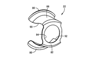
- FIG. 4 is a perspective view showing the bracket 22 alone.
- the hook mounting structure 10 of this embodiment is disposed at the rear of the vehicle, and the hook mounting module 12 is mounted on the left and right sides corresponding to the side members 14 on the left and right sides of the vehicle (the right side member is not shown).
- a pair of connecting portions 28 and 30 are provided. Each of these connecting portions 28 and 30 includes a mounting plate 20 and a crash box 26, and a bumper reinforcement 24 is integrally fixed to a tip portion of the crash box 26.
- the mounting plate 20 is integrally fixed to the support plate 34 of the side member 14 by a plurality of bolts 32, and the nut member 16 is attached to the left connecting portion 28 so that the hook member 18 can be attached.
- the mounting plate 20 is integrally provided.
- the side member 14 has a cylindrical shape with a rectangular cross section and is disposed along the front-rear direction of the vehicle.
- the rear end portion of the side member 14 is arc-welded so that the support plate 34 is substantially perpendicular to the front-rear direction of the vehicle.
- the mounting plate 20 is integrally fastened by the bolt 32 in a state of being superposed so as to be in surface contact with the support plate 34.
- the insertion plate 20 is provided with three insertion holes 36, and is attached to the support plate 34 by three bolts 32.
- the bumper reinforcement 24 functions as a bumper reinforcement member or a support member, and a bumper main body (not shown) is mounted integrally.
- the crash box 26 is a cylindrical member, and the mounting plate 20 is integrally joined to one end portion in the axial direction by arc welding, and the bumper reinforcement 24 is integrally fixed to the other end portion by welding.
- the mounting plate 20 is provided with a bulging portion 38 corresponding to the shape of the end of the crash box 26, and the crash box 26 is arranged and arc-welded so as to be positioned by the bulging portion 38.
- a flange 40 bent at a substantially right angle is provided at the upper and lower edges of the bumper reinforcement 24, and the flange 40 is overlapped with the crash box 26. And are integrally joined by spot welding.
- the crash box 26 is attached to the rear end portion of the side member 14 via the attachment plate 20 in a posture in which the axial direction is substantially parallel to the longitudinal direction of the vehicle, and an impact is applied from the rear of the vehicle to apply the axial compression load. When it is received, it is crushed into a bellows shape, and the impact energy is absorbed by the deformation at that time, and the impact applied to the structural member of the vehicle such as the side member 14 is alleviated.
- the crash box 26 has a rectangular shape in which a cross section perpendicular to the axial direction is long in the vertical direction, and a wide width that forms two parallel sides in the rectangular cross section.
- a pair of left and right side walls 42 and 44 of the flat plate shape are provided with concave grooves 46 and 48 that are bent symmetrically so as to protrude inwardly in a trapezoidal shape in the middle part over the entire length in the axial direction.
- the crush box 26 is composed of a pair of halves 50 and 52 having a substantially M-shaped cross section that is divided into left and right substantially symmetrically in parallel with the axial direction.
- the pair of halves 50 and 52 are formed by subjecting a thin plate material to bending or the like by pressing, and upper and lower side edge portions 50a and 52a on the opening side are overlapped with each other to perform spot welding. Are formed into a cylindrical shape by being integrally joined together.
- the nut member 16 is a cylindrical member, and is fixed integrally to the mounting plate 20 in an attitude in which the axial direction is substantially parallel to the longitudinal direction of the vehicle, like the crash box 26.
- a female screw 58 is provided on the center line of the nut member 16 to which a male screw 56 provided at the distal end portion of the shaft portion 54 of the hook member 18 is screwed.
- the shaft portion 54 of the hook member 18 is also provided with a fitting shaft portion 60 and a taper portion 62 having a diameter larger than that of the male screw 56, and the nut member 16 is substantially connected to the fitting shaft portion 60.
- a fitting hole 64 fitted so as to come into contact with each other and a tapered surface 66 closely attached to the tapered portion 62 are formed concentrically.
- the hook member 18 is firmly attached to the nut member 16 with a predetermined mounting strength.
- the presence of the nut member 16 may hinder the compressive deformation in the axial direction of the kush box 26, but the axial dimension of the nut member 16 is 1 ⁇ 2 or less of the axial dimension of the crash box 26, and is predetermined. The impact energy absorption performance is ensured.
- the hook member 18 is provided with an annular hook 70 integrally with the shaft portion 54, and the hook 70 is attached to the nut member 16 in a state of protruding from the bumper reinforcement 24 toward the rear side of the vehicle. That is, a reinforcing washer 74 having a through hole 72 is integrally fixed to the bumper reinforcement 24 by welding means such as spot welding, and the hook member 18 has a shaft portion 54 penetrating from the male screw 56 side. The shaft portion 54 is inserted into the hole 72 and screwed into the female screw 58 of the nut member 16, and the shaft portion 54 is supported by engagement with the through hole 72.
- the hook member 18 is used when towing another vehicle by connecting a rope or the like to the hook 70, but is also used when fixing the vehicle with a rope or the like when transporting the vehicle by a ship or the like.
- a relatively large load may be applied in a direction intersecting the axial direction.
- the shaft portion 54 comes into contact with the through hole 72, the shaft portion 54 is supported by the bumper reinforcement 24 via the reinforcing washer 74, and the load is distributed to the bumper reinforcement 24.
- the deformation and displacement of 54 are suppressed.
- transformation and displacement of the axial part 54 are suppressed, the fall and damage of the nut member 16 with which the hook member 18 is screwed together are also suppressed.
- a portion of the bumper reinforcement 24 to which the reinforcing washer 74 is fixed is provided with a relief hole having a diameter larger than that of the through hole 72, and the shaft portion 54 of the hook member 18 is provided in the through hole 72 of the reinforcing washer 74. Is supported by contact.
- the through hole 72 corresponds to an insertion hole into which the shaft portion 54 is inserted when the hook member 18 is screwed to the nut member 16 and supports the shaft portion 54 when the hook member 18 is mounted.
- the through hole 72 is as small as possible.
- the nut member 16 and the bumper reinforcement 24 provided on the mounting plate 20 are reduced.
- the hook member 18 cannot be screwed to the nut member 16 due to misalignment with the reinforcing washer 74 provided on the nut.
- the bumper reinforcement 24 in which the reinforcing washer 74 is disposed is integrally welded to the crash box 26, and the crash box 26 is integrally welded to the mounting plate 20.
- the nut member 16 is integrally welded to the mounting plate 20, and the nut member 16, the mounting plate 20, the bumper reinforcement 24, and the crash box 26 are integrally joined in advance to form a hook mounting module. 12 is configured. For this reason, compared with the case where they are separately fixed to the side member 14 with bolts or the like, it is possible to easily secure the mutual positional accuracy at the stage where they are fixed integrally.
- the misalignment between the nut member 16 provided at 20 and the reinforcing washer 74 provided at the bumper reinforcement 24 is suppressed. This makes it possible to reduce the size of the through-hole 72 while reliably preventing the hook member 18 from being screwed to the nut member 16 due to misalignment, and allows the hook member 18 to cross the axial direction.
- the hook member 18 is used by being attached to the nut member 16 when necessary, and a predetermined gap is provided between the through hole 72 and the shaft portion 54 for attachment and detachment.
- a bracket 22 is provided on the mounting plate 20 of the left connecting portion 28 to which the hook member 18 is mounted, and the nut member 16 is attached by the mounting plate 20 and the bracket 22. It is designed to be firmly and integrally supported.
- the bracket 22 has a bottomed cylindrical shape, and the outer peripheral edge of the flange 80 provided on the opening side thereof is integrally joined to the mounting plate 20 by arc welding.
- a mounting hole 84 is provided in the bottom portion 82 on the distal end side that is separated from the mounting plate 20, and the nut member 16 is disposed across the mounting hole 84 and the mounting plate 20.
- the diameter of the mounting hole 84 is substantially equal to the outer diameter of the nut member 16, and the mounting plate 20 is provided with a mounting hole 86 having a diameter substantially equal to the outer diameter of the nut member 16.
- Two concentric arrangements are provided so as to be fitted in the mounting holes 84 and 86, and two axially spaced locations are integrally joined to the mounting plate 20 and the bracket 22 by arc welding.
- the nut member 16 is supported at two locations separated in the axial direction, the mounting strength of the nut member 16 with respect to the mounting plate 20 is increased, and the deformation and displacement of the hook member 18 are suppressed by the reinforcing washer 74. In combination with this, the fall and breakage of the nut member 16 are more effectively suppressed. Further, since the nut member 16 is fixed to the bracket 22 and the mounting plate 20 at two locations separated in the axial direction, the posture of the nut member 16 can be managed with high accuracy, and the reinforcing washer 74 provided on the bumper reinforcement 24 is provided.
- the through hole 72 can be disposed concentrically with high accuracy, and the through hole 72 can be further reduced to improve the support performance for the shaft portion 54.
- a pair of notches 90 and 92 are provided on the cylindrical side wall 88 of the bracket 22 along the cross-sectional contour of the crash box 26 in order to avoid interference with the crash box 26. That is, since the left and right side walls 42 and 44 of the crush box 26 of the present embodiment are provided with the concave grooves 46 and 48, as shown in FIG. A pair of notches 90 and 92 are provided corresponding to 46 and 48. These notches 90 and 92 reach the outer peripheral edge of the flange 80. Accordingly, it is not necessary to make the crash box 26 larger than necessary so as not to interfere with the bracket 22, and the crash box 26 can be configured to be compact and inexpensive, and the crash box 26 is positioned by the engagement between the crash box 26 and the notches 90 and 92.
- the axial cross section is curved in an arc shape, and the support strength in the longitudinal direction of the nut member 16 is enhanced.
- the crash box 26 is integrally fixed to the mounting plate 20 so that the nut member 16 is accommodated inside, and the tip of the crash box 26 is fixed.
- the bumper reinforcement 24 is integrally fixed, the impact transmitted from the bumper reinforcement 24 to the side member 14 at the time of a vehicle collision is reduced while being compactly configured.
- the nut member 16, the mounting plate 20, the bracket 22, the bumper reinforcement 24, and the crash box 26 are integrally welded to each other in advance to constitute the hook mounting module 12. Since it is attached to the side member 14 by the plurality of bolts 32 through the attachment plate 20 in the state of the attachment module 12, the attachment work to the side member 14 is easy, and the mutual positions at the stage where they are integrally welded Accuracy can be secured easily. Therefore, misalignment between the nut member 16 provided on the mounting plate 20 and the reinforcing washer 74 provided on the bumper reinforcement 24 is suppressed, and the hook member 18 can be screwed onto the nut member 16 due to misalignment.
- the through hole 72 of the reinforcing washer 74 is made small so that the deformation of the shaft portion 54 of the hook member 18 when a load in the direction crossing the axial direction is applied to the hook member 18. The displacement can be more appropriately suppressed.
- a pair of connecting portions 28 and 30 having a mounting plate 20 and a crash box 26 are integrally provided on the left and right sides of the bumper reinforcement 24 corresponding to the left and right side members 14 of the vehicle. Since the nut member 16 is integrally fixed to the attachment plate 20 of the connecting portion 28, the hook attachment module 12 can be easily attached to the left and right side members 14.
- the bracket 22 is integrally welded to the mounting plate 20 of the left connecting portion 28, and the nut member 16 straddles the mounting hole 84 of the bracket 22 and the mounting hole 86 of the mounting plate 20. Since it is integrally welded to the mounting plate 20 and the bracket 22 at two locations that are arranged apart from each other in the axial direction, the mounting strength of the nut member 16 to the mounting plate 20 is increased, and the reinforcing washer In combination with the suppression of the deformation and displacement of the shaft portion 54 of the hook member 18 by 74, the fall and breakage of the nut member 16 is further effectively suppressed.
- the posture of the nut member 16 can be managed with high accuracy, and the nut member 16 is provided on the bumper reinforcement 24.
- the through hole 72 of the reinforcing washer 74 can be disposed concentrically with high accuracy, and the through hole 72 can be further reduced to improve the support performance for the shaft portion 54.
- the crash box 26 is directly joined to the mounting plate 20 by welding, and the bracket 22 is accommodated in the crash box 26 and notches 90 and 92 for avoiding interference with the crash box 26.
- Is provided on the side wall 88 it is not necessary to make the crash box 26 larger than necessary, and it can be constructed in a compact and inexpensive manner.
- the crash box 26 is positioned by the engagement between the crash box 26 and the cutouts 90 and 92, positioning work when welding the crash box 26 to the mounting plate 20 is facilitated, while the rigidity of the bracket 22 itself is increased. Therefore, drawing or the like when forming the bracket 22 by press working becomes easy.
- the bumper reinforcement 24 is provided with a reinforcing washer 74, and the through hole 72 of the reinforcing washer 74 functions as an insertion hole for supporting the shaft portion 54 of the hook member 18. Therefore, the bumper reinforcement 24 The deformation and displacement of the shaft portion 54 of the hook member 18 can be more appropriately suppressed while suppressing the deformation and breakage of the hook member 18.
- the bracket 100 shown in FIG. 5A is used in place of the bracket 22 of the above-described embodiment.
- the bracket 100 has a cylindrical side wall 88 without a pair of notches 90 and 92, and an annular flange. 80. That is, in the embodiment, as shown in FIG. 2, the crush box 26 provided with the concave grooves 46 and 48 projecting inwardly on the left and right side walls 42 and 44 is used, but as shown in FIG.
- the crush box 102 having the rectangular cross section (the octagonal cross section including the inclination of the corner) having the flat side walls 42 and 44 without the concave grooves 46 and 48 there is sufficient space around the nut member 16.
- FIG. 5A is a perspective view of the bracket 100 corresponding to FIG. 4, and FIG. 5B is a cross-sectional view corresponding to FIG.
- FIG. 6 is a perspective view showing the vicinity of the left connecting portion 110 to which the hook member 18 is attached.
- FIGS. 7A and 7B are views taken along the arrows VIIA-VIIA and VIIB-VIIB in FIG. It is sectional drawing of a view part, (c) is an enlarged view of the VIIC part in (b).
- FIGS. 7A and 7B show the state in which the connecting portion 110 is fixed to the side member 14 and the hook member 18 is attached to the nut member 16.
- FIG. 8 is a perspective view showing the bracket 112 used in the connecting portion 110 alone.
- the bracket 112 has a flat quadrangular bottomed box shape, and the peripheral portions of the three flanges 114a to 114c except for the lower flange 114d in the middle of the four flanges 114a to 114d provided on the opening side thereof, respectively. It is integrally joined to the mounting plate 20 by arc welding.
- the three flanges 114b to 114d excluding the upper flange 114a are relatively large, and an insertion hole 116 is provided at the same position as the insertion hole 36.
- the bolts 32 and the mounting plate 20 are integrated with the support plate 34. Fixed.
- the mounting hole 84 is provided in the bottom 118 on the front end side of the bracket 112 that is separated from the mounting plate 20, and the nut member 16 is arranged across the mounting hole 84 and the mounting plate 20 in the same manner as in the above embodiment.
- the boundary portion between the rectangular square cylindrical side wall 120 and the flanges 114a to 114d and the boundary portion between the side wall 120 and the bottom portion 118 are both curved in an arc shape in the axial direction. Support strength in the longitudinal direction is increased.
- a step 122 is provided on the entire periphery of the boundary portion between the side wall 120 and the bottom portion 118, and the crush box 26 has an end portion in the state where the axial end edge is locked to the step 122.
- the crash box 26 has concave grooves 46 and 48 and an inclined portion. However, the portions other than the concave grooves 46 and 48 and the inclined portion, that is, the left and right side walls 42 and 44, respectively.
- the axial load applied to the crash box 26 is reliably transmitted from the bracket 112 to the side member 14, and the crash box 26 is appropriately compressed in the axial direction to absorb the impact. it can. Since the crash box 26 is disposed between the bracket 112 and the bumper reinforcement 24 as described above, the overlapping dimension with the nut member 16 is shortened, and the length of the crash box 26 in the axial direction is related thereto. Can be shortened.
- the nut member 16, the mounting plate 20, the bumper reinforcement 24, the crash box 26, and the bracket 112 are integrally welded together in advance to constitute the hook mounting module 124, and the hook mounting module 124. In this state, it is attached to the side member 14 by a plurality of bolts 32 via the attachment plate 20.
- the attaching operation to the side member 14 is easy, and it is possible to easily ensure the mutual positional accuracy at the stage where they are integrally welded, and the nut member 16 provided on the attaching plate 20 and The misalignment with the reinforcing washer 74 provided in the bumper reinforcement 24 is suppressed, the through hole 72 of the reinforcing washer 74 is reduced, and the deformation and displacement of the shaft portion 54 of the hook member 18 can be more appropriately suppressed. As a result, substantially the same effects as those of the above embodiment can be obtained.
Landscapes
- Engineering & Computer Science (AREA)
- Mechanical Engineering (AREA)
- Transportation (AREA)
- Chemical & Material Sciences (AREA)
- Combustion & Propulsion (AREA)
- Body Structure For Vehicles (AREA)
Abstract
Le but de la présente invention consiste, même dans le cas où il est possible de supprimer de la façon appropriée la déformation d'un élément crochet en réduisant la dimension d'un trou d'insertion ménagé dans un renforcement de pare-chocs, à permettre qu'une partie barre de l'élément crochet puisse s'insérer dans le trou d'insertion et être fixée de la façon appropriée au moyen d'un écrou. Un module de fixation de crochet (12) comprend les éléments suivants qui sont préalablement assemblés en une seule pièce par soudage : un écrou (16) ; une plaque d'attache (20) ; une ferrure (22) ; un renforcement de pare-chocs (24) ; une boîte d'écrasement (26). Etant donné que le module de fixation de crochet (12), dans l'état précité, est attaché à un élément latéral (14) par l'intermédiaire de la plaque d'attache (20) au moyen d'un boulon (32), la précision d'alignement mutuelle des éléments ci-dessus peut être facilement assurée dans l'étape de soudage. En conséquence, l'invention peut être réalisée de manière à éviter un désalignement entre l'écrou (16) monté sur la plaque d'attache (20) et la rondelle de renforcement (74) disposée sur le renforcement de pare-chocs (24) et de telle sorte que, grâce à la réduction de la dimension du trou débouchant (72) (le trou d'insertion) de la rondelle de renforcement (74), la déformation de la partie barre (54) est encore évitée de la façon appropriée.
Applications Claiming Priority (2)
| Application Number | Priority Date | Filing Date | Title |
|---|---|---|---|
| JP2011090468A JP2012224099A (ja) | 2011-04-14 | 2011-04-14 | 車両のフック取付構造およびフック取付モジュール |
| JP2011-090468 | 2011-04-14 |
Publications (1)
| Publication Number | Publication Date |
|---|---|
| WO2012140930A1 true WO2012140930A1 (fr) | 2012-10-18 |
Family
ID=47009116
Family Applications (1)
| Application Number | Title | Priority Date | Filing Date |
|---|---|---|---|
| PCT/JP2012/051473 Ceased WO2012140930A1 (fr) | 2011-04-14 | 2012-01-24 | Structure de fixation de crochet et module de fixation de crochet pour véhicule |
Country Status (2)
| Country | Link |
|---|---|
| JP (1) | JP2012224099A (fr) |
| WO (1) | WO2012140930A1 (fr) |
Cited By (11)
| Publication number | Priority date | Publication date | Assignee | Title |
|---|---|---|---|---|
| FR2998842A1 (fr) * | 2012-12-03 | 2014-06-06 | Peugeot Citroen Automobiles Sa | Ensemble comprenant une poutre avant de vehicule automobile et deux absorbeurs de choc frontal en tole d'acier |
| EP2762367A1 (fr) * | 2013-02-01 | 2014-08-06 | Faurecia Bloc Avant | Ensemble de pare-chocs pour véhicule automobile |
| EP2783883A1 (fr) | 2013-03-28 | 2014-10-01 | Volvo Car Corporation | Dispositif de remorquage de véhicule, élément structurel de véhicule et véhicule comprenant un élément structurel de véhicule |
| CN104417466A (zh) * | 2013-08-19 | 2015-03-18 | 株式会社神户制钢所 | 保险杠加强件及其制造方法 |
| TWI583579B (zh) * | 2013-10-09 | 2017-05-21 | Nippon Steel & Sumitomo Metal Corp | Collision box and manufacturing method thereof |
| GB2563594A (en) * | 2017-06-19 | 2018-12-26 | Jaguar Land Rover Ltd | Releasable connector for a vehicle |
| FR3074750A1 (fr) * | 2017-12-11 | 2019-06-14 | Compagnie Plastic Omnium | Systeme d'absorption de choc pour vehicule automobile |
| CN110962513A (zh) * | 2019-11-26 | 2020-04-07 | 奇瑞汽车股份有限公司 | 拖车钩螺母盒 |
| GB2582406A (en) * | 2017-06-19 | 2020-09-23 | Jaguar Land Rover Ltd | Releasable connector for a vehicle |
| GB2585007A (en) * | 2019-06-24 | 2020-12-30 | Jaguar Land Rover Ltd | Composite crush can |
| US20210221187A1 (en) * | 2020-01-17 | 2021-07-22 | Toyota Jidosha Kabushiki Kaisha | Towing hook attachment structure |
Families Citing this family (3)
| Publication number | Priority date | Publication date | Assignee | Title |
|---|---|---|---|---|
| DE102018107487A1 (de) * | 2018-03-28 | 2019-10-02 | Benteler Automobiltechnik Gmbh | Stoßfängeranordnung für ein Kraftfahrzeug |
| JP7428063B2 (ja) * | 2020-04-20 | 2024-02-06 | マツダ株式会社 | 車両の後部車体構造 |
| EP4360961A1 (fr) * | 2022-10-25 | 2024-05-01 | Constellium Singen GmbH | Système d absorption de choc pour un véhicule à moteur |
Citations (4)
| Publication number | Priority date | Publication date | Assignee | Title |
|---|---|---|---|---|
| JP2002053066A (ja) * | 2000-08-10 | 2002-02-19 | Fuji Heavy Ind Ltd | 車両用牽引フックの取付構造 |
| JP2008013157A (ja) * | 2006-07-10 | 2008-01-24 | Nissan Motor Co Ltd | 自動車のバンパ構造 |
| JP2008018792A (ja) * | 2006-07-11 | 2008-01-31 | Toyoda Iron Works Co Ltd | 車両用衝撃吸収部材 |
| JP2008037220A (ja) * | 2006-08-04 | 2008-02-21 | Kobe Steel Ltd | 脱着式牽引フックの取付構造 |
-
2011
- 2011-04-14 JP JP2011090468A patent/JP2012224099A/ja not_active Withdrawn
-
2012
- 2012-01-24 WO PCT/JP2012/051473 patent/WO2012140930A1/fr not_active Ceased
Patent Citations (4)
| Publication number | Priority date | Publication date | Assignee | Title |
|---|---|---|---|---|
| JP2002053066A (ja) * | 2000-08-10 | 2002-02-19 | Fuji Heavy Ind Ltd | 車両用牽引フックの取付構造 |
| JP2008013157A (ja) * | 2006-07-10 | 2008-01-24 | Nissan Motor Co Ltd | 自動車のバンパ構造 |
| JP2008018792A (ja) * | 2006-07-11 | 2008-01-31 | Toyoda Iron Works Co Ltd | 車両用衝撃吸収部材 |
| JP2008037220A (ja) * | 2006-08-04 | 2008-02-21 | Kobe Steel Ltd | 脱着式牽引フックの取付構造 |
Cited By (23)
| Publication number | Priority date | Publication date | Assignee | Title |
|---|---|---|---|---|
| CN104918831A (zh) * | 2012-12-03 | 2015-09-16 | 标致·雪铁龙汽车公司 | 包括机动车辆前梁和两个钢板式正面碰撞缓冲器的组件 |
| WO2014087066A1 (fr) * | 2012-12-03 | 2014-06-12 | Peugeot Citroen Automobiles Sa | Ensemble comprenant une poutre avant de vehicule automobile et deux absorbeurs de choc frontal en tole d'acier |
| FR2998842A1 (fr) * | 2012-12-03 | 2014-06-06 | Peugeot Citroen Automobiles Sa | Ensemble comprenant une poutre avant de vehicule automobile et deux absorbeurs de choc frontal en tole d'acier |
| EP2762367A1 (fr) * | 2013-02-01 | 2014-08-06 | Faurecia Bloc Avant | Ensemble de pare-chocs pour véhicule automobile |
| FR3001680A1 (fr) * | 2013-02-01 | 2014-08-08 | Faurecia Bloc Avant | Ensemble de pare-chocs pour vehicule automobile |
| CN104070947B (zh) * | 2013-03-28 | 2018-04-10 | 沃尔沃汽车公司 | 车辆牵引设备、车辆结构元件及包括车辆结构元件的车辆 |
| EP2783883A1 (fr) | 2013-03-28 | 2014-10-01 | Volvo Car Corporation | Dispositif de remorquage de véhicule, élément structurel de véhicule et véhicule comprenant un élément structurel de véhicule |
| CN104070947A (zh) * | 2013-03-28 | 2014-10-01 | 沃尔沃汽车公司 | 车辆牵引设备、车辆结构元件及包括车辆结构元件的车辆 |
| US9221312B2 (en) | 2013-03-28 | 2015-12-29 | Volvo Car Corporation | Vehicle towing device, vehicle structural member and vehicle comprising a vehicle structural member |
| CN104417466A (zh) * | 2013-08-19 | 2015-03-18 | 株式会社神户制钢所 | 保险杠加强件及其制造方法 |
| US10363892B2 (en) | 2013-10-09 | 2019-07-30 | Nippon Steel Corporation | Crash box and method for producing the same |
| TWI583579B (zh) * | 2013-10-09 | 2017-05-21 | Nippon Steel & Sumitomo Metal Corp | Collision box and manufacturing method thereof |
| GB2563594A (en) * | 2017-06-19 | 2018-12-26 | Jaguar Land Rover Ltd | Releasable connector for a vehicle |
| GB2563594B (en) * | 2017-06-19 | 2020-01-22 | Jaguar Land Rover Ltd | Releasable connector for a vehicle |
| GB2582406A (en) * | 2017-06-19 | 2020-09-23 | Jaguar Land Rover Ltd | Releasable connector for a vehicle |
| GB2582406B (en) * | 2017-06-19 | 2021-01-13 | Jaguar Land Rover Ltd | Releasable connector for a vehicle |
| FR3074750A1 (fr) * | 2017-12-11 | 2019-06-14 | Compagnie Plastic Omnium | Systeme d'absorption de choc pour vehicule automobile |
| WO2019115552A1 (fr) * | 2017-12-11 | 2019-06-20 | Compagnie Plastic Omnium | Systeme d'absorption de choc pour vehicule automobile |
| GB2585007A (en) * | 2019-06-24 | 2020-12-30 | Jaguar Land Rover Ltd | Composite crush can |
| GB2585007B (en) * | 2019-06-24 | 2021-11-17 | Jaguar Land Rover Ltd | Composite crush can |
| CN110962513A (zh) * | 2019-11-26 | 2020-04-07 | 奇瑞汽车股份有限公司 | 拖车钩螺母盒 |
| US20210221187A1 (en) * | 2020-01-17 | 2021-07-22 | Toyota Jidosha Kabushiki Kaisha | Towing hook attachment structure |
| US11760143B2 (en) * | 2020-01-17 | 2023-09-19 | Toyota Jidosha Kabushiki Kaisha | Towing hook attachment structure |
Also Published As
| Publication number | Publication date |
|---|---|
| JP2012224099A (ja) | 2012-11-15 |
Similar Documents
| Publication | Publication Date | Title |
|---|---|---|
| WO2012140930A1 (fr) | Structure de fixation de crochet et module de fixation de crochet pour véhicule | |
| US7815245B2 (en) | Front part structure of vehicle body | |
| US7540559B2 (en) | Rear structure of vehicle body | |
| JP5664637B2 (ja) | 車体前部構造 | |
| JP5861869B2 (ja) | 車両の牽引用フックの固定部構造 | |
| US20160176442A1 (en) | Vehicle front portion structure | |
| US20140327268A1 (en) | Vehicle underbody structure | |
| JP6278030B2 (ja) | 車両前部構造 | |
| JP6308194B2 (ja) | 車両のエネルギ吸収構造 | |
| JP5910667B2 (ja) | 車体前部構造 | |
| CN106394678A (zh) | 车辆下部结构 | |
| JP2016007928A (ja) | 車体構造 | |
| JP6565714B2 (ja) | バッテリ搭載構造 | |
| JP6183693B2 (ja) | バンパーメンバのナット取付構造 | |
| JP2005162049A (ja) | 車両の衝撃吸収部材 | |
| JP2011111113A (ja) | 車両用衝撃吸収具及び車両用バンパ装置 | |
| JP6115821B2 (ja) | エンジンマウントブラケットの取付構造 | |
| JP2010228512A (ja) | 車体の前部構造 | |
| JP6519554B2 (ja) | 車両後部構造 | |
| JP5765272B2 (ja) | トーイングヒッチメンバ及び車体構造 | |
| JP2014136545A (ja) | サスペンションメンバ及びこれを備えた車両前部構造 | |
| JP6292088B2 (ja) | 車両前部構造 | |
| JP5397603B2 (ja) | マフラー支持構造 | |
| JP2018203079A (ja) | 車両用ドアストライカ取付構造 | |
| JP5682814B2 (ja) | 車体の補強構造 |
Legal Events
| Date | Code | Title | Description |
|---|---|---|---|
| 121 | Ep: the epo has been informed by wipo that ep was designated in this application |
Ref document number: 12770914 Country of ref document: EP Kind code of ref document: A1 |
|
| DPE2 | Request for preliminary examination filed before expiration of 19th month from priority date (pct application filed from 20040101) | ||
| NENP | Non-entry into the national phase |
Ref country code: DE |
|
| WA | Withdrawal of international application |