WO2012140931A1 - 流体制御装置およびポンプ接続方法 - Google Patents
流体制御装置およびポンプ接続方法 Download PDFInfo
- Publication number
- WO2012140931A1 WO2012140931A1 PCT/JP2012/051493 JP2012051493W WO2012140931A1 WO 2012140931 A1 WO2012140931 A1 WO 2012140931A1 JP 2012051493 W JP2012051493 W JP 2012051493W WO 2012140931 A1 WO2012140931 A1 WO 2012140931A1
- Authority
- WO
- WIPO (PCT)
- Prior art keywords
- pump
- communication hole
- hole
- air
- communicating
- Prior art date
- Legal status (The legal status is an assumption and is not a legal conclusion. Google has not performed a legal analysis and makes no representation as to the accuracy of the status listed.)
- Ceased
Links
Images


Classifications
-
- F—MECHANICAL ENGINEERING; LIGHTING; HEATING; WEAPONS; BLASTING
- F04—POSITIVE - DISPLACEMENT MACHINES FOR LIQUIDS; PUMPS FOR LIQUIDS OR ELASTIC FLUIDS
- F04B—POSITIVE-DISPLACEMENT MACHINES FOR LIQUIDS; PUMPS
- F04B17/00—Pumps characterised by combination with, or adaptation to, specific driving engines or motors
- F04B17/003—Pumps characterised by combination with, or adaptation to, specific driving engines or motors driven by piezoelectric means
-
- F—MECHANICAL ENGINEERING; LIGHTING; HEATING; WEAPONS; BLASTING
- F04—POSITIVE - DISPLACEMENT MACHINES FOR LIQUIDS; PUMPS FOR LIQUIDS OR ELASTIC FLUIDS
- F04B—POSITIVE-DISPLACEMENT MACHINES FOR LIQUIDS; PUMPS
- F04B45/00—Pumps or pumping installations having flexible working members and specially adapted for elastic fluids
- F04B45/04—Pumps or pumping installations having flexible working members and specially adapted for elastic fluids having plate-like flexible members, e.g. diaphragms
- F04B45/047—Pumps having electric drive
Definitions
- the present invention relates to a fluid control device and a pump connection method for filling an air storage unit with air using a pump.
- Patent Document 1 discloses a conventional piezoelectric pump.
- FIG. 1 is a diagram illustrating a pumping operation in the third-order resonance mode of the piezoelectric pump disclosed in Patent Document 1.
- the piezoelectric pump includes a pump main body 10, a diaphragm 19 whose outer peripheral portion is fixed to the pump main body 10, a piezoelectric element 23 attached to a central portion of the diaphragm 19, and a substantially central portion of the diaphragm 19.
- the diaphragm 19 is a metal plate.
- the piezoelectric element 23 is formed in a size that covers the first opening 11 and does not reach the second opening 12.
- the piezoelectric element 23 applies a voltage of a predetermined frequency to the piezoelectric element 23 to bend the portion of the diaphragm 19 facing the first opening 11 and the portion of the diaphragm 19 facing the second opening 12 in the opposite direction. Deform.
- the piezoelectric pump of Patent Document 1 sucks fluid from the second opening 12 and discharges it from the first opening 11.
- the pump pressure may be insufficient, for example, when connecting to a cuff of a blood pressure monitor. At this time, for example, as shown in FIG. 2, it is conceivable to increase the pump pressure by connecting two or more piezoelectric pumps in series.
- the flow rate of the air tank 9 is almost the same as when one piezoelectric pump 2 is connected to the air tank 9 despite the increase in power consumption, that is, the air tank 9. Since the air filling speed does not increase, power is wasted. Therefore, it may be possible to drive only one piezoelectric pump 2 while the pressure of the air tank 9 is low. However, when only one piezoelectric pump 2 is driven, the flow rate resistance of the other piezoelectric pump 1 connected in series is remarkably large, so that almost no flow rate is generated.
- An object of the present invention is to provide a fluid control device and a pump connection method capable of reducing power consumption while the air pressure of the air storage unit is low.
- the fluid control device of the present invention has the following configuration in order to solve the above problems.
- a first pump having a first pump chamber and a first suction hole and a first discharge hole communicating with each other via the first pump chamber; A second suction hole and a second discharge hole communicating with each other via the second pump chamber and the second pump chamber, wherein the second suction hole communicates with the first discharge hole; A second pump in communication with the air reservoir; A first communication hole communicating with the outside of the apparatus main body and a second communication hole communicating with the first discharge hole and the second suction hole are allowed, and inflow of fluid from the first communication hole to the second communication hole is allowed. And a check valve for prohibiting outflow of fluid from the second communication hole to the first communication hole.
- the air storage unit when the air storage unit starts to be filled with air, driving is started from the second pump.
- the air storage unit is, for example, a cuff for measuring blood pressure.
- the second pump starts the pumping operation, external air flows into the pump chamber of the second pump through the check valve. And air is sent to the air storage part from the discharge hole of the 2nd pump, and the pressure (air pressure) in the air storage part increases.
- the air passes through the pump chamber of the first pump and does not pass through the check valve. Flows into the pump chamber. Furthermore, air is sent from the discharge hole of the second pump to the air storage unit, and the pressure (air pressure) in the air storage unit increases to the target pressure.
- a first check valve having a diaphragm constituting a second valve chamber communicating with the first valve valve is provided.
- the air storage unit when the air storage unit starts to be filled with air, driving is started from the second pump.
- the air storage unit is, for example, a cuff for measuring blood pressure.
- the air in the second valve chamber of the first check valve flows into the pump chamber of the second pump from the third communication hole.
- the pressure in the second valve chamber is reduced, the diaphragm is opened, and the first communication hole and the second communication hole are communicated with each other.
- outside air is sucked from the first communication hole of the first check valve, and air passes through the first communication hole, the first valve chamber, and the second communication hole of the first check valve. It flows into the pump chamber. And air is sent to the air storage part from the discharge hole of the 2nd pump, and the pressure (air pressure) in the air storage part increases.
- the air passes through the pump chamber of the first pump and the second through the third communication hole of the first check valve. Flows into the valve chamber.
- the pressure in the second valve chamber is increased, and the diaphragm blocks the communication between the first communication hole and the second communication hole.
- air flows into the pump chamber in the second pump via the pump chamber in the first pump without passing through the first check valve.
- air is sent from the discharge hole of the second pump to the air storage unit, and the pressure (air pressure) in the air storage unit increases to the target pressure.
- a third pump having three discharge holes communicating with the air storage unit; A first communication hole communicating with the outside of the apparatus main body, a second communication hole communicating with the second discharge hole and the third suction hole, and a third communication hole communicating with the second discharge hole and the third suction hole; A first valve chamber communicating with the first communication hole and the second communication hole, and a third communication hole communicating with the first communication hole and the third communication hole.
- a second check valve having a diaphragm that forms a two-valve chamber; The second discharge hole of the second pump communicates with the air storage unit via the third pump.
- the driving is started from the third pump.
- the air in the second valve chamber of the second check valve flows into the pump chamber of the third pump from the third communication hole.
- the pressure in the second valve chamber decreases, the diaphragm is opened, and the first communication hole and the second communication hole communicate with each other.
- outside air is sucked from the first communication hole of the second check valve, and air passes through the first communication hole, the first valve chamber, and the second communication hole of the second check valve. It flows into the pump chamber. And air is sent to the air storage part from the discharge hole of a 3rd pump, and the pressure (air pressure) in an air storage part increases.
- the last pump having the shortest connection distance to the air storage unit is connected between the air storage unit and the air storage unit is filled by at least the pumping operation of the last pump. Equipped with a quick exhaust section for quick exhaust
- the quick exhaust part is A first communication hole that communicates with the discharge hole of the last-stage pump, a second communication hole that communicates with the air storage unit, and a third communication hole that communicates with the air storage unit and the second communication hole are formed.
- a check valve housing a first valve chamber that divides the inside of the check valve housing and communicates with the first communication hole and the second communication hole, and a second valve chamber that communicates with the third communication hole;
- a first valve comprising: a check valve, An exhaust valve housing formed with a fourth communication hole communicating with the discharge hole of the last-stage pump, a fifth communication hole communicating with the air storage unit, and a sixth communication hole communicating with the outside of the apparatus body;
- a second diaphragm that divides the inside of the exhaust valve housing and constitutes a third valve chamber communicating with the fifth communication hole and the sixth communication hole and a fourth valve chamber communicating with the fourth communication hole;
- the second pump causes air to flow from the discharge hole of the second pump to the check valve of the quick exhaust part.
- the quick exhaust check valve when the forward discharge pressure from the first communication hole to the second communication hole is generated by the pumping operation of the second pump, the first diaphragm opens and the first communication hole and the second communication hole The communication hole communicates.
- the second diaphragm blocks the communication between the fifth communication hole and the sixth communication hole.
- the air passes through the pump chamber of the first pump and the second through the third communication hole of the first check valve. Flows into the valve chamber.
- the pressure in the second valve chamber is increased, and the diaphragm blocks the communication between the first communication hole and the second communication hole.
- air flows into the pump chamber in the second pump via the pump chamber in the first pump.
- air is sent from the discharge hole of the second pump to the air storage part via the first communication hole and the second communication hole of the check valve of the quick exhaust part, and the pressure (air pressure) in the air storage part is the target pressure. It rises to.
- the fluid control device stops the pumping operation of all the pumps.
- the volumes of all the pump chambers and the fourth valve chamber are extremely small compared to the volume of air that can be accommodated in the air storage unit. Therefore, when the pumping operation of all the pumps stops, the air in all the pump chambers and the fourth valve chamber is immediately exhausted from the suction holes of the first pump to the outside of the fluid control device via the discharge holes of the first pump. The As a result, in the exhaust valve of the quick exhaust part, as soon as the pumping operation of the pump is stopped, the pressure in the fourth valve chamber drops below the pressure in the third valve chamber.
- the second diaphragm opens and the fifth communication hole and the sixth communication hole communicate with each other in the exhaust valve of the quick exhaust section. Thereby, the air of an air storage part is rapidly exhausted from a 6th communicating hole via a 5th communicating hole.
- a control unit that starts driving in order from a pump having a short connection distance to the air storage unit among all the pumps, The control unit monitors the air pressure of the air storage unit and starts driving the next pump in response to the increase in the air pressure.
- control unit instructs each pump to start driving based on the air pressure value of the air storage unit.
- the pump includes an actuator that is not substantially constrained in the periphery and bends and vibrates from the center to the periphery.
- a plane portion arranged in close proximity to the actuator;
- One or a plurality of central vent holes disposed at or near the center of the actuator facing region facing the actuator of the planar portion; Is provided.
- peripheral portion of the actuator (of course, the central portion) is not substantially constrained, there is little loss due to the bending vibration of the actuator, and a high pressure and a large flow rate can be obtained while being small and low-profile.
- the actuator has a disk shape, it is in a rotationally symmetric (concentric) vibration state, so that no unnecessary gap is generated between the actuator and the flat portion, and the operating efficiency of the pump is increased. .
- the center or the vicinity of the center is a thin plate portion capable of bending vibration, and the peripheral portion is a thick plate portion substantially constrained.
- the actuator vibrates, so that the thin plate portion of the opposing surface centering on the vent hole vibrates, so that the vibration amplitude can be substantially increased, thereby increasing the pressure and flow rate. it can.
- the gap between the actuator and the flat portion automatically changes according to load fluctuations. Can be made. For example, when the actuator is lightly loaded, the gap can be positively increased to increase the flow rate, and when the load is high, the connecting part bends and the gap between the actuator and the flat part is automatically reduced. It is possible to operate with pressure.
- the pump connection method of the fluid control device of the present invention has the following configuration in order to solve the above-mentioned problems.
- a first pump having a first pump chamber and a first suction hole and a first discharge hole communicating with each other via the first pump chamber;
- a t-pump having a t-th suction hole and a t-th discharge hole communicating with each other via the t-th pump chamber and the t-th pump chamber;
- a first communication hole communicating with the outside of the apparatus main body, a check valve housing formed with a second communication hole and a third communication hole, and dividing the inside of the check valve housing into the first communication hole;
- a t-1 check valve having a diaphragm constituting a first valve chamber communicating with the second communication hole and a second valve chamber communicating with the third communication hole,
- the tth suction hole and the t-1 discharge hole are connected, the nth discharge hole and the air storage unit are connected, and the t-1 discharge hole, the tth suction hole, and the t-1th discharge hole are connected.
- the second communication hole of the check valve was connected, and the t-1 discharge hole and the t suction hole were connected to the third communication hole of the t-1 check valve.
- the pump connection method in this configuration is used in the fluid control device of (1) or (2). Thereby, there exists an effect similar to said (1) or said (2).
- power consumption can be reduced while the air pressure of the air storage unit is low.
- FIG. 2 is a block diagram showing a method for connecting a general piezoelectric pump 1, piezoelectric pump 2, and air tank 9. It is a block diagram which shows the structure of the principal part of the fluid control apparatus 100 of 1st Embodiment of this invention.
- FIG. 4 is a block diagram showing a method for connecting the piezoelectric pump 101, the piezoelectric pump 201, the check valve 202, and the air tank 9 shown in FIG. It is a disassembled perspective view of the piezoelectric pumps 101 and 201 with which the fluid control apparatus 100 of 1st Embodiment of this invention is equipped.
- FIG. 6A is a cross-sectional view of the main part of the piezoelectric pumps 101 and 201 shown in FIG.
- FIG. 6B is a cross-sectional view of the main part of piezoelectric pumps 101 ′ and 201 ′ that are modifications of the piezoelectric pumps 101 and 201 shown in FIG. 5.
- movement is explanatory drawing which shows the flow of air when the piezoelectric pumps 101 and 201 shown in FIG. 3 are performing the pumping operation
- 6 is a graph showing changes in air pressure of the air tank 9; FIG.
- FIG. 11A shows a connection method of the piezoelectric pump 101, the piezoelectric pump 201, the piezoelectric pump 301, the check valve 202, the check valve 302, and the air tank 9 provided in the fluid control apparatus 200 according to the second embodiment of the present invention.
- FIG. FIG. 11B illustrates a piezoelectric pump 101, a piezoelectric pump 201, a piezoelectric pump 901, a check valve 202, a check valve 902, and a check valve 902 included in a fluid control apparatus 200 ′ according to a modification of the second embodiment of the present invention.
- 4 is a block diagram showing a method for connecting the air tank 9.
- FIG. 12 It is a block diagram which shows the structure of the principal part of the fluid control apparatus 300 of 3rd Embodiment of this invention. It is explanatory drawing which shows the flow of air when the piezoelectric pump 201 shown in FIG. 12 is performing the pumping operation
- FIG. 3 is a block diagram illustrating a configuration of a main part of the fluid control device 100 according to the first embodiment of the present invention.
- FIG. 4 is a block diagram showing a connection method of the piezoelectric pump 101, the piezoelectric pump 201, the check valve 202, and the air tank 9 shown in FIG.
- the fluid control device 100 includes a piezoelectric pump 101, a piezoelectric pump 201, a check valve 202, and a control unit 111, and is connected to the air tank 9.
- the housing 110 of the fluid control device 100 is formed with a connection port 106A that communicates with the rubber tube 9A of the air tank 9, and suction ports 107A and 107B for sucking air outside the housing 110.
- the piezoelectric pump 101 and the piezoelectric pump 201 are connected to the air tank 9 in series via a check valve 202.
- the control unit 111 is constituted by a microcomputer, for example, and controls the operation of each unit of the apparatus main body.
- the control unit 111 starts driving sequentially from the piezoelectric pumps having a short connection distance to the air tank 9 among all the piezoelectric pumps.
- the control unit 111 monitors the pressure (air pressure) in the air tank 9 and starts driving the next-stage piezoelectric pump in response to the increase in air pressure.
- the fluid control device 100 which will be described in detail later, first drives only the piezoelectric pump 201 when the air tank 9 is filled with compressed air. Due to the pumping operation of the piezoelectric pump 201, outside air is sucked from the suction port 107 ⁇ / b> B via the check valve 202, and air is sent from the discharge hole 55 of the piezoelectric pump 201 to the air tank 9 to increase the pressure (air pressure) in the air tank 9. . Thereafter, when the air pressure of the air tank 9 exceeds a certain pressure, the fluid control device 100 drives the piezoelectric pump 101.
- FIG. 5 is an exploded perspective view of the piezoelectric pumps 101 and 201 provided in the fluid control apparatus 100 according to the first embodiment of the present invention.
- 6A is a cross-sectional view of the main part of the piezoelectric pumps 101 and 201 shown in FIG.
- the piezoelectric pump 101 includes a substrate 91, a planar portion 51, a spacer 53A, a reinforcing plate 43, a vibration plate unit 60, a piezoelectric element 42, a spacer 53B, an electrode conduction plate 70, a spacer 53C, and a lid portion 54, which are sequentially stacked. It has the structure. Since the piezoelectric pump 201 has the same structure as the piezoelectric pump 101, description thereof is omitted.
- a piezoelectric element 42 is attached to the upper surface of the disk-shaped diaphragm 41, and a reinforcing plate 43 is attached to the lower surface of the diaphragm 41, and the diaphragm 41, the piezoelectric element 42, and the reinforcing plate 43 form a disk.
- a shaped actuator 40 is configured.
- the vibration plate 41 is a metal plate having a larger linear expansion coefficient than the piezoelectric element 42 and the reinforcing plate 43, and is heated and cured at the time of bonding, so that the piezoelectric element 42 is appropriately warped without warping.
- the piezoelectric element 42 can be prevented from cracking.
- the diaphragm 41 may be made of a material having a large linear expansion coefficient such as phosphor bronze (C5210) or stainless steel SUS301, and the reinforcing plate 43 may be made of 42 nickel, 36 nickel or stainless steel SUS430.
- the piezoelectric element 42 is preferably formed of lead zirconate titanate ceramics. In this case, the thickness of the spacer 53B is preferably the same as that of the piezoelectric element 42 or slightly thicker.
- the diaphragm 41, the piezoelectric element 42, and the reinforcing plate 43 may be arranged in the order of the piezoelectric element 42, the reinforcing plate 43, and the diaphragm 41 from the top. Also in this case, the linear expansion coefficient is adjusted by reversing the materials of the reinforcing plate 43 and the diaphragm 41 so that an appropriate compressive stress remains in the piezoelectric element 42.
- a diaphragm support frame 61 is provided around the diaphragm 41, and the diaphragm 41 is connected to the diaphragm support frame 61 by a connecting portion 62.
- the connecting portion 62 is formed in a thin ring shape, and has an elastic structure with a small spring constant elasticity. Therefore, the diaphragm 41 is flexibly supported at two points with respect to the diaphragm support frame 61 by the two connecting portions 62. Therefore, the bending vibration of the diaphragm 41 is hardly disturbed. That is, the peripheral portion of the actuator 40 (of course, the central portion) is not substantially restrained.
- the spacer 53A is provided to hold the actuator 40 with a certain gap from the flat portion 51. External terminals 63 for electrical connection are formed on the diaphragm support frame 61.
- the diaphragm 41, the diaphragm support frame 61, the connecting portion 62, and the external terminal 63 are formed by punching a metal plate, and the diaphragm unit 60 is configured by these.
- a resin spacer 53B is bonded and fixed to the upper surface of the diaphragm support frame 61.
- the thickness of the spacer 53B is the same as or slightly thicker than that of the piezoelectric element 42, constitutes a part of the pump housing 80, and electrically insulates the electrode conduction plate 70 and the diaphragm unit 60 described below.
- a metal electrode conduction plate 70 is bonded and fixed on the spacer 53B.
- the electrode conduction plate 70 includes a frame portion 71 that is opened in a substantially circular shape, an internal terminal 73 that projects into the opening, and an external terminal 72 that projects outward.
- the tip of the internal terminal 73 is soldered to the surface of the piezoelectric element 42.
- the vibration of the internal terminal 73 can be suppressed.
- a resin spacer 53C is bonded and fixed on the electrode conduction plate 70.
- the spacer 53 ⁇ / b> C has the same thickness as the piezoelectric element 42.
- the spacer 53C is a spacer for preventing the solder portion of the internal terminal 73 from contacting the lid portion 54 when the actuator vibrates. Further, the surface of the piezoelectric element 42 is prevented from excessively approaching the lid portion 54 and the vibration amplitude is prevented from lowering due to air resistance. Therefore, the thickness of the spacer 53C may be the same as that of the piezoelectric element 42 as described above.
- the lid 54 is placed on the upper portion of the spacer 53C and covers the periphery of the actuator 40. Therefore, the fluid sucked through the central vent hole 52 is discharged from the discharge hole 55.
- the discharge hole 55 may be provided at the center of the lid portion 54, but is not required to be provided at the center of the lid portion 54 because it is a discharge hole that releases positive pressure in the pump housing 80 including the lid portion 54.
- a central vent hole 52 (suction hole) is formed at the center of the flat portion 51.
- a spacer 53 ⁇ / b> A added to the thickness of the reinforcing plate 43 by about several tens of ⁇ m is inserted.
- the connecting portion 62 spring terminal
- connection part 62 was provided in two places, you may provide in three or more places.
- the connecting portion 62 does not disturb the vibration of the actuator 40, but has some influence on the vibration. For example, by connecting (holding) at three locations, more natural holding is possible, and cracking of the piezoelectric element is prevented. You can also
- one or a plurality of peripheral vent holes 56A and 56B may be provided in the peripheral portion of the actuator facing region.
- the pressure in the gap between the actuator facing regions varies from moment to moment with the bending vibration of the actuator 40 in both the central portion and the peripheral portion.
- a negative pressure is generated in the central portion, and the peripheral portion
- a positive pressure that balances it is generated. Therefore, if the peripheral vent holes 56A and 56B are provided in the peripheral portion of the actuator facing region, the positive pressure generated in the peripheral portion can be used, and suction / discharge can be performed on the same surface. Therefore, the peripheral vent holes 56A and 56B may be used as the discharge holes of the piezoelectric pump 101 as they are, or the peripheral vent holes 56A and 56B may be communicated with the discharge holes provided separately to perform concentrated exhaust.
- a substrate 91 having a cylindrical opening 92 formed at the center is provided at the lower portion of the flat portion 51.
- a part of the flat portion 51 is exposed at the opening 92 of the substrate 91.
- This circular exposed portion can vibrate at substantially the same frequency as that of the actuator 40 due to pressure fluctuation accompanying vibration of the actuator 40.
- Due to the configuration of the flat portion 51 and the substrate 91, the center or the vicinity of the actuator facing region of the flat portion 51 is a thin plate portion capable of bending vibration, and the peripheral portion is a substantially constrained thick plate portion.
- the natural frequency of the circular thin plate portion is designed to be the same as or slightly lower than the drive frequency of the actuator 40.
- the actuator 40 bends and vibrates concentrically, and in response to the vibration of the actuator 40, the exposed portion ( The thin plate portion also vibrates with a large amplitude. If the vibration phase of the plane part 51 is delayed (for example, delayed by 90 °) from the vibration phase of the actuator 40, the variation in the thickness of the gap space between the plane part 51 and the actuator 40 substantially increases. . As a result, the capacity of the pump can be further improved.
- the piezoelectric pump 101 and the piezoelectric pump 201 are connected to the air tank 9 in series as shown in FIGS. More specifically, the central vent hole 52 of the piezoelectric pump 101 communicates with the suction port 107 A for taking in outside air, and the discharge hole 55 of the piezoelectric pump 101 communicates with the central vent hole 52 of the piezoelectric pump 201. Further, the discharge hole 55 of the piezoelectric pump 201 communicates with the connection port 106A.
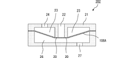
- FIG. 7 is a cross-sectional view of the main part of the check valve 202 provided in the fluid control apparatus 100 according to the first embodiment of the present invention.
- the check valve 202 includes a cylindrical check valve housing 21 and a diaphragm 108A made of a circular thin film.
- the check valve housing 21 communicates with the first communication hole 24 communicating with the suction port 107B for taking in outside air, the discharge hole 55 of the piezoelectric pump 101, and the central ventilation hole 52 (suction hole) of the piezoelectric pump 201.
- the diaphragm 108 ⁇ / b> A is fixed to the check valve housing 21 in contact with the valve seat 20.
- the diaphragm 108 ⁇ / b> A divides the inside of the check valve housing 21 into a ring-shaped first valve chamber 23 that communicates with the first communication hole 24 and a second valve chamber 26 that communicates with the third communication hole 27.
- the material of the diaphragm 108A is an elastic member such as ethylene propylene rubber or silicone rubber.
- the valve seat 20 is formed in the check valve housing 21 so as to pressurize the diaphragm 108A.
- the check valve 202 opens or closes the valve by the diaphragm 108A coming into contact with or away from the valve seat 20 due to the pressure difference between the first valve chamber 23 and the second valve chamber 26.
- FIG. 8 is an explanatory diagram showing the flow of air when the piezoelectric pump 201 shown in FIG. 3 is performing the pumping operation.
- FIG. 9 is an explanatory diagram showing the flow of air when the piezoelectric pumps 101 and 201 shown in FIG. 3 are performing the pumping operation.
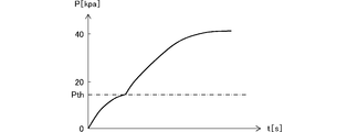
- FIG. 10 is a graph showing changes in the air pressure of the air tank 9.
- the control unit 111 starts driving from the piezoelectric pump 201 having a short connection distance to the air tank 9 among all the pumps when starting the air filling (see FIG. 8).
- the piezoelectric pump 201 starts the pumping operation
- the air in the second valve chamber 26 flows into the pump chamber 45 of the piezoelectric pump 201 from the third communication hole 27.
- the check valve 202 the pressure in the second valve chamber 26 decreases, the diaphragm 108A is opened, and the first communication hole 24 and the second communication hole 22 communicate with each other.
- the control unit 111 monitors the pump pressure, which is the discharge pressure of the piezoelectric pump 201 shown in FIG. When it is determined that the pump pressure has exceeded a certain pressure Pth (15 kPa in this embodiment), the controller 111 starts driving the next piezoelectric pump 101 (see FIG. 9).
- FIG. 11A shows a connection method of the piezoelectric pump 101, the check valve 202, the piezoelectric pump 201, the check valve 302, the piezoelectric pump 301, and the air tank 9 provided in the fluid control apparatus 200 according to the second embodiment of the present invention.
- FIG. 11A shows a connection method of the piezoelectric pump 101, the check valve 202, the piezoelectric pump 201, the check valve 302, the piezoelectric pump 301, and the air tank 9 provided in the fluid control apparatus 200 according to the second embodiment of the present invention.
- the fluid control device 200 of this embodiment is different from the fluid control device 100 in that a piezoelectric pump 301 and a check valve 302 are provided. Other configurations are the same.
- the piezoelectric pump 301 has the same structure as the piezoelectric pump 101 shown in FIGS.
- the piezoelectric pump 301 is connected in series with the piezoelectric pump 201 via a check valve 302. Specifically, the discharge hole 55 of the piezoelectric pump 201 communicates with the central vent hole 52 of the piezoelectric pump 301, and the discharge hole 55 of the piezoelectric pump 301 communicates with the connection port 106A.
- the check valve 302 has the same structure as the check valve 202 shown in FIG. However, the second communication hole 22 of the check valve housing 21 communicates with the discharge hole 55 of the piezoelectric pump 201 and the central ventilation hole 52 of the piezoelectric pump 301. Further, the third communication hole 27 of the check valve housing 21 communicates with the discharge hole 55 of the piezoelectric pump 201 and the central vent hole 52 of the piezoelectric pump 301.
- the control unit 111 starts driving in order from the piezoelectric pump 301 having a short connection distance to the air tank 9 among all the piezoelectric pumps.
- the control unit 111 monitors the pump pressure of the piezoelectric pump 301 as the air pressure of the air tank 9, and starts driving the next-stage piezoelectric pump in response to the increase in air pressure. For example, when it is determined that the pump pressure has exceeded 15 kPa while only the piezoelectric pump 301 is performing the pumping operation, the control unit 111 starts driving the next piezoelectric pump 201. Then, when it is determined that the pump pressure has exceeded 30 kPa while the piezoelectric pumps 301 and 201 are performing the pumping operation, the control unit 111 starts driving the next piezoelectric pump 101.
- FIG. 11B illustrates a piezoelectric pump 101, a check valve 202, a piezoelectric pump 201, a check valve 902, a piezoelectric pump 901, and a piezoelectric pump 101 included in a fluid control apparatus 200 ′ according to a modification of the second embodiment of the present invention.
- 4 is a block diagram showing a method for connecting the air tank 9.
- the piezoelectric pump 101 is represented as a first pump
- the piezoelectric pump 201 is represented as a second pump
- the nth stage piezoelectric pump 901 is represented as an nth pump.
- the check valve 902 is an (n-1) th stage check valve.
- the fluid control device 200 includes the first pump 101, the t-th pump, and the t-1 check valve.
- t is an integer from 2 to n.
- the t-th suction hole of the t-th pump communicates with the t-1 discharge hole of the t-1 pump
- the n-th discharge hole of the n-th pump communicates with the air tank 9.
- the t-1 discharge hole of the t-1 pump, the t suction hole of the t pump, and the second communication hole 22 of the t-1 check valve communicate with each other.
- the one discharge hole, the t-th suction hole of the t-th pump, and the third communication hole 27 of the t-1 check valve communicate with each other.
- FIG. 12 is a block diagram illustrating a configuration of a main part of a fluid control device 300 according to the third embodiment of the present invention.
- the fluid control device 300 of this embodiment is different from the fluid control device 100 in that it includes a quick exhaust unit 309 capable of quick exhaust, and the other configurations are the same. Therefore, the fluid control device 300 is a device suitable for connection to a cuff 109 for blood pressure measurement that requires quick exhaust after filling with compressed air.
- the quick exhaust unit 309 includes a check valve 102, an exhaust valve 103, and an exhaust port 106B, and connects the last stage pump 201 and the cuff 109.
- the rubber tube 109A of the cuff 109 is connected to the connection port 106A of the housing 310 of the fluid control device 300. Further, the housing 310 of the fluid control device 300 is further formed with an exhaust port 106 ⁇ / b> B for exhausting the air of the cuff 109.
- the structure of the check valve 102 is the same as the structure of the check valve 202 shown in FIG. However, the first communication hole 24 of the check valve 102 communicates with the discharge hole 55 of the piezoelectric pump 201. Further, the second communication hole 22 of the check valve 102 communicates with the cuff 109. The third communication hole 27 of the check valve 102 communicates with the second communication hole 22 and the cuff 109.
- the exhaust valve 103 includes a cylindrical exhaust valve housing 31 and a diaphragm 108B made of a circular thin film.
- the exhaust valve casing 31 has a fourth communication hole 37 communicating with the discharge hole 55 of the piezoelectric pump 201, a fifth communication hole 34 communicating with the cuff 109, and a sixth communication hole 32 communicating with the outside of the fluid control device 300. And the valve seat 30 protruding from the periphery of the sixth communication hole 32 toward the diaphragm 108B.
- the diaphragm 108 ⁇ / b> B is fixed to the exhaust valve housing 31 in contact with the valve seat 30. Further, the diaphragm 108B divides the inside of the exhaust valve housing 31 to constitute a fourth valve chamber 36 communicating with the fourth communication hole 37 and a ring-shaped third valve chamber 33 communicating with the fifth communication hole 34. To do.
- the material of the diaphragm 108B is an elastic member such as ethylene propylene rubber or silicone rubber.
- the exhaust valve 103 opens or closes the valve by the diaphragm 108B contacting or separating from the valve seat 30 due to the pressure difference between the fourth valve chamber 36 and the third valve chamber 33.
- FIG. 13 is an explanatory diagram showing the flow of air when the piezoelectric pump 201 shown in FIG. 12 is performing a pumping operation.
- FIG. 14 is an explanatory diagram showing the air flow when the piezoelectric pumps 101 and 201 shown in FIG. 12 are performing the pumping operation.
- FIG. 15 is an explanatory diagram showing the air flow immediately after the piezoelectric pumps 101 and 201 shown in FIG. 12 stop the pumping operation.
- the control unit 111 starts driving sequentially from the piezoelectric pump 201 having the shortest connection distance to the cuff 109 among all the pumps (see FIG. 13).
- the piezoelectric pump 201 starts the pumping operation
- the air in the second valve chamber 26 of the check valve 202 flows into the pump chamber 45 from the third communication hole 27 through the central vent hole 52 of the piezoelectric pump 201.
- the pressure in the second valve chamber 26 decreases, the diaphragm 108A is opened, and the first communication hole 24 and the second communication hole 22 communicate with each other.
- the piezoelectric pump 201 causes air to flow from the discharge hole 55 of the piezoelectric pump 201 into the check valve 102 of the quick exhaust unit 309.
- the check valve 102 when a forward discharge pressure from the first communication hole 24 to the second communication hole 22 is generated by the pumping operation of the piezoelectric pump 201, the diaphragm 108 ⁇ / b> A is opened and the first communication hole 24 is connected to the second communication hole 24. The hole 22 communicates.
- the exhaust valve 103 of the quick exhaust part 309 when the fourth valve chamber 36 is pressurized by the pumping operation of the piezoelectric pump 201, the diaphragm 108 ⁇ / b> B seals the sixth communication hole 32.
- air is sent from the piezoelectric pump 201 to the cuff 109 via the first communication hole 24 and the second communication hole 22 of the check valve 102, and the pressure (air pressure) in the cuff 109 increases (see FIG. 10). .
- the fluid control device 300 has a structure in which the second communication hole 22 and the third communication hole 27 of the check valve 102 in the quick exhaust unit 309 communicate with each other.
- the check valve 102 has a shape in which the first communication hole 24 is formed on the outer periphery with the second communication hole 22 as the center.
- the pressure in the first valve chamber 23 is slightly higher than the pressure in the second valve chamber 26, and the check valve 102 maintains the state in which the diaphragm 108A is opened. Further, since the pressure difference between the first valve chamber 23 and the second valve chamber 26 is small, the pressure difference is not extremely biased, and the diaphragm 108A can be prevented from being damaged.
- the fluid control device 300 has a structure in which the second communication hole 22 of the check valve 102 and the fifth communication hole 34 of the exhaust valve 103 communicate with each other in the quick exhaust unit 309.
- the exhaust valve 103 has a shape in which a communication hole 34 is formed on the outer periphery around the sixth communication hole 32.
- the pressure in the fourth valve chamber 36 is slightly higher than that in the third valve chamber 33, and the exhaust valve 103 maintains the state in which the diaphragm 108B is closed. Further, since the pressure difference between the fourth valve chamber 36 and the third valve chamber 33 is small, the pressure difference is not extremely biased, and the diaphragm 108B can be prevented from being damaged.
- the control unit 111 monitors the pump pressure of the piezoelectric pump 201 shown in FIG. When it is determined that the pump pressure has exceeded a certain pressure (15 kPa in this embodiment), the control unit 111 starts driving the next piezoelectric pump 101 (see FIG. 14).
- the control unit 111 stops the pumping operation of the piezoelectric pumps 101 and 201 (see FIG. 15).
- the volumes of the pump chamber 45, the first valve chamber 23, and the fourth valve chamber 36 of each of the piezoelectric pumps 101 and 201 are extremely small compared to the volume of air that can be accommodated in the cuff 109. Therefore, when the pumping operation of the piezoelectric pumps 101 and 201 is stopped, the air in the pump chamber 45, the first valve chamber 23, and the fourth valve chamber 36 is fluidized via the central vent hole 52 and the opening 92 of the piezoelectric pump 101. The air is immediately exhausted from the suction port 107A of the control device 300 to the outside of the fluid control device 300.
- the pressure of the cuff 109 is applied to the second valve chamber 26 of the check valve 102 and the third valve chamber 33 of the exhaust valve 103 in the quick exhaust unit 309.
- the check valve 102 as soon as the pumping operation of the piezoelectric pumps 101 and 201 is stopped, the pressure in the first valve chamber 23 immediately falls below the pressure in the second valve chamber 26.
- the exhaust valve 103 of the quick exhaust unit 309 when the pumping operation of the piezoelectric pumps 101 and 201 is stopped, the pressure in the fourth valve chamber 36 immediately decreases from the pressure in the third valve chamber 33.
- power consumption can be reduced while the air pressure of the cuff 109 is low. It is also possible to quickly exhaust air from the cuff 109 after the cuff 109 is filled with compressed air.
- n-stage piezoelectric pumps can be connected in series as shown in FIG.
- the unimorph type actuator that bends and vibrates is provided.
- a piezoelectric element may be attached to both surfaces of the diaphragm so that the bimorph type bends and vibrates.
- the exhaust valve 103 connects the fifth communication hole 34 to the cuff 109 and connects the sixth communication hole 32 to the exhaust port 106B.
- the cuff 109 may be connected in a state where the sixth communication hole 32 is disposed, and the sixth communication hole 32 may be connected to the exhaust port 106B in a state where the sixth communication hole 32 is disposed in the position of the fifth communication hole 34 in FIG.
- this connection method even when the pressure of the cuff 109 fluctuates due to body movement or the like, there is an effect that unintended exhaust is hardly generated.
Landscapes
- Engineering & Computer Science (AREA)
- Mechanical Engineering (AREA)
- General Engineering & Computer Science (AREA)
- Reciprocating Pumps (AREA)
- Compressors, Vaccum Pumps And Other Relevant Systems (AREA)
Abstract
空気貯蔵部の空気圧が低い間の消費電力を削減できる流体制御装置及びポンプ接続方法を提供する。流体制御装置(100)は、圧電ポンプ(101)と圧電ポンプ(201)と逆止弁(202)と制御部(111)とを備え、エアタンク(9)に接続される。エアタンク(9)に圧縮空気を充填する時、流体制御装置(100)はまず圧電ポンプ(201)を駆動する。吸引口(107B)から外気が逆止弁(202)を介して吸引され、空気が圧電ポンプ(201)の吐出孔(55)からエアタンク(9)へ送出する。圧電ポンプ(201)のポンプ圧力が一定圧力を超えると、流体制御装置(100)は圧電ポンプ(101)の駆動を開始する。吸引口(107A)から外気が吸引され、空気が圧電ポンプ(101)を経由して逆止弁(202)を経由せず圧電ポンプ(201)の吐出孔(55)からエアタンク(9)へ送出し、エアタンク(9)の空気圧を目標圧力まで高める。
Description
この発明は、ポンプを用いて空気貯蔵部に空気を充填する流体制御装置およびポンプ接続方法に関する。
特許文献1に従来の圧電ポンプが開示されている。
図1は特許文献1の圧電ポンプの3次共振モードでのポンピング動作を示す図である。当該圧電ポンプは、ポンプ本体10と、外周部がポンプ本体10に対して固定されたダイヤフラム19と、このダイヤフラム19の中央部に貼り付けられた圧電素子23と、ダイヤフラム19の略中央部と対向するポンプ本体10の部位に形成された第1開口部11と、ダイヤフラム19の中央部と外周部との中間領域又はこの中間領域と対向するポンプ本体の部位に形成された第2開口部12とを備える。ダイヤフラム19は金属板である。圧電素子23は、第1開口部11を覆い、且つ第2開口部12まで達しない大きさに形成されている。
図1は特許文献1の圧電ポンプの3次共振モードでのポンピング動作を示す図である。当該圧電ポンプは、ポンプ本体10と、外周部がポンプ本体10に対して固定されたダイヤフラム19と、このダイヤフラム19の中央部に貼り付けられた圧電素子23と、ダイヤフラム19の略中央部と対向するポンプ本体10の部位に形成された第1開口部11と、ダイヤフラム19の中央部と外周部との中間領域又はこの中間領域と対向するポンプ本体の部位に形成された第2開口部12とを備える。ダイヤフラム19は金属板である。圧電素子23は、第1開口部11を覆い、且つ第2開口部12まで達しない大きさに形成されている。
圧電素子23は、圧電素子23に所定周波数の電圧を印加することにより、第1開口部11に対向するダイヤフラム19の部分と第2開口部12に対向するダイヤフラム19の部分とを相反方向に屈曲変形する。特許文献1の圧電ポンプは、第2開口部12から流体を吸込み、第1開口部11から吐出するものである。
上記特許文献1の圧電ポンプを含む従来のポンプにおいて、例えば血圧計のカフに接続する場合など、ポンプ圧力が不足することがある。この際、例えば、図2に示されるように、圧電ポンプを2つ以上直列に接続することでポンプ圧力を増大させることが考えられる。
しかしながら、図2に示すように2個の圧電ポンプ1、2を直列に接続し、エアタンク9に空気を充填する場合、当然のことながら2倍の消費電力が必要となる。2個の圧電ポンプ1、2を直列に接続した場合の最大ポンプ圧力は、1個の圧電ポンプ2をエアタンク9に接続した場合の2倍の圧力まで到達できるが、最大流量は、1個の圧電ポンプ2をエアタンク9に接続した場合と変わらない。
そのため、エアタンク9の圧力(空気圧)が低い間は、消費電力が増大しているにも拘わらず、流量が1個の圧電ポンプ2をエアタンク9に接続した場合とほとんど変わらないため、即ちエアタンク9への空気充填速度が増えないため、電力を無駄に消費することになる。そこで、エアタンク9の圧力が低い間は、圧電ポンプ2を1個だけ駆動しておくことも考えられる。しかし、圧電ポンプ2を1個だけ駆動した場合、直列に接続している他方の圧電ポンプ1の流路抵抗が著しく大きいため、ほとんど流量が生じない。特に、圧電ポンプ1、2共に高い圧力を実現しようとした場合、圧電ポンプ1、2内のポンプ室体積は小さくしておく方が好ましく、その結果、流量抵抗は大きくなってしまう。そのため、圧電ポンプ1、2は、常に2個とも駆動する必要がある。
従って、図2に示すように2個の圧電ポンプ1、2を直列に接続し、エアタンク9に空気を充填する場合、エアタンク9の圧力が低い間の電力効率が悪いという問題があった。
本発明の目的は、空気貯蔵部の空気圧が低い間の消費電力を削減できる流体制御装置およびポンプ接続方法を提供することにある。
本発明の流体制御装置は、前記課題を解決するために以下の構成を備えている。
(1)第1ポンプ室と前記第1ポンプ室を介して互いに連通する第1吸引孔および第1吐出孔とを有する第1ポンプと、
第2ポンプ室と前記第2ポンプ室を介して互いに連通する第2吸引孔および第2吐出孔とを有し、前記第2吸引孔が前記第1吐出孔に連通し、前記第2吐出孔が空気貯蔵部に連通する第2ポンプと、
装置本体の外部に連通する第1連通孔と前記第1吐出孔および前記第2吸引孔に連通する第2連通孔を有し、第1連通孔から第2連通孔への流体の流入は許容し、第2連通孔から第1連通孔への流体の流出を禁止する逆止弁と、を備える。
第2ポンプ室と前記第2ポンプ室を介して互いに連通する第2吸引孔および第2吐出孔とを有し、前記第2吸引孔が前記第1吐出孔に連通し、前記第2吐出孔が空気貯蔵部に連通する第2ポンプと、
装置本体の外部に連通する第1連通孔と前記第1吐出孔および前記第2吸引孔に連通する第2連通孔を有し、第1連通孔から第2連通孔への流体の流入は許容し、第2連通孔から第1連通孔への流体の流出を禁止する逆止弁と、を備える。
この構成では、空気貯蔵部に空気の充填を開始するとき、第2ポンプから駆動を開始させる。空気貯蔵部は、例えば血圧測定用のカフである。第2ポンプがポンピング動作を開始すると、外部の空気が逆止弁を通って、第2ポンプのポンプ室へ流入する。そして、空気が第2ポンプの吐出孔から空気貯蔵部へ送出され、空気貯蔵部内の圧力(空気圧)が高まる。
その後、第1ポンプが駆動を開始し、第1ポンプ、第2ポンプがポンピング動作を行うと、空気が第1ポンプのポンプ室を経由して、逆止弁を通らずに、第2ポンプ内のポンプ室に流入する。さらに、空気が第2ポンプの吐出孔から空気貯蔵部へ送出され、空気貯蔵部内の圧力(空気圧)が目標圧力まで高まる。
この構成では、空気貯蔵部の圧力が低い間、第2ポンプだけを駆動した場合でも、流路抵抗の大きな第1ポンプでなく流路抵抗の小さい逆止弁を介して外気を吸引するため、十分な流量が生じる。そのため、空気貯蔵部の圧力(空気圧)が低い間、第1ポンプ、第2ポンプの全てを駆動する必要が無く、第2ポンプを駆動するだけで済む。従って、この構成によれば、空気貯蔵部の空気圧が低い間の消費電力を削減できる。
(2)装置本体の外部に連通する第1連通孔と前記第1吐出孔および前記第2吸引孔に連通する第2連通孔と前記第1吐出孔および前記第2吸引孔に連通する第3連通孔とが形成された逆止弁筐体と、前記逆止弁筐体内を分割して、前記第1連通孔および前記第2連通孔に連通する第1バルブ室と前記第3連通孔に連通する第2バルブ室とを構成するダイヤフラムと、を有する第1逆止弁を備えた。
この構成では、空気貯蔵部に空気の充填を開始するとき、第2ポンプから駆動を開始させる。空気貯蔵部は、例えば血圧測定用のカフである。第2ポンプがポンピング動作を開始すると、第1逆止弁の第2バルブ室の空気が第3連通孔から第2ポンプのポンプ室へ流入する。これにより、第1逆止弁では、第2バルブ室の圧力が低下し、ダイヤフラムが開放して第1連通孔と第2連通孔とが連通する。この結果、外気が第1逆止弁の第1連通孔から吸引され、空気が第1逆止弁の第1連通孔、第1バルブ室、及び第2連通孔を経由して第2ポンプのポンプ室へ流入する。そして、空気が第2ポンプの吐出孔から空気貯蔵部へ送出され、空気貯蔵部内の圧力(空気圧)が高まる。
その後、第1ポンプが駆動を開始し、第1ポンプ、第2ポンプがポンピング動作を行うと、空気が第1ポンプのポンプ室を経由して第1逆止弁の第3連通孔から第2バルブ室へ流入する。これにより、第1逆止弁では第2バルブ室の圧力が高まり、ダイヤフラムが第1連通孔と第2連通孔の連通を遮断する。この結果、空気が、第1逆止弁を通らずに第1ポンプ内のポンプ室を経由して、第2ポンプ内のポンプ室に流入する。さらに、空気が第2ポンプの吐出孔から空気貯蔵部へ送出され、空気貯蔵部内の圧力(空気圧)が目標圧力まで高まる。
この構成では、空気貯蔵部の圧力が低い間、第2ポンプだけを駆動した場合でも、流路抵抗の大きな第1ポンプでなく流路抵抗の小さい第1逆止弁を介して外気を吸引するため、十分な流量が生じる。そのため、空気貯蔵部の圧力(空気圧)が低い間、第1ポンプ、第2ポンプの全てを駆動する必要が無く、第2ポンプを駆動するだけで済む。
従って、この構成によれば、空気貯蔵部の空気圧が低い間の消費電力を削減できる。
従って、この構成によれば、空気貯蔵部の空気圧が低い間の消費電力を削減できる。
(3)第3ポンプ室と前記第3ポンプ室を介して互いに連通する第3吸引孔および第3吐出孔とを有し、前記第3吸引孔が前記第2吐出孔に連通し、前記第3吐出孔が前記空気貯蔵部に連通する第3ポンプと、
装置本体の外部に連通する第1連通孔と前記第2吐出孔および前記第3吸引孔に連通する第2連通孔と前記第2吐出孔および前記第3吸引孔に連通する第3連通孔とが形成された逆止弁筐体と、前記逆止弁筐体内を分割して、前記第1連通孔および前記第2連通孔に連通する第1バルブ室と前記第3連通孔に連通する第2バルブ室とを構成するダイヤフラムと、を有する第2逆止弁と、を備え、
前記第2ポンプの前記第2吐出孔は、前記第3ポンプを介して前記空気貯蔵部に連通する。
装置本体の外部に連通する第1連通孔と前記第2吐出孔および前記第3吸引孔に連通する第2連通孔と前記第2吐出孔および前記第3吸引孔に連通する第3連通孔とが形成された逆止弁筐体と、前記逆止弁筐体内を分割して、前記第1連通孔および前記第2連通孔に連通する第1バルブ室と前記第3連通孔に連通する第2バルブ室とを構成するダイヤフラムと、を有する第2逆止弁と、を備え、
前記第2ポンプの前記第2吐出孔は、前記第3ポンプを介して前記空気貯蔵部に連通する。
この構成では、空気貯蔵部に空気の充填を開始するとき、第3ポンプから駆動を開始させる。第3ポンプがポンピング動作を開始すると、第2逆止弁の第2バルブ室の空気が第3連通孔から第3ポンプのポンプ室へ流入する。これにより、第2逆止弁では、第2バルブ室の圧力が低下し、ダイヤフラムが開放して第1連通孔と第2連通孔とが連通する。この結果、外気が第2逆止弁の第1連通孔から吸引され、空気が第2逆止弁の第1連通孔、第1バルブ室、及び第2連通孔を経由して第3ポンプのポンプ室へ流入する。そして、空気が第3ポンプの吐出孔から空気貯蔵部へ送出され、空気貯蔵部内の圧力(空気圧)が高まる。
この構成では、空気貯蔵部の圧力が低い間、第3ポンプだけを駆動した場合でも、流路抵抗の大きな第1ポンプ、第2ポンプでなく流路抵抗の小さい第2逆止弁を介して外気を吸引するため、十分な流量が生じる。また、第2ポンプ、第3ポンプを駆動した場合でも、流路抵抗の大きな第1ポンプでなく流路抵抗の小さい第1逆止弁を介して外気を吸引するため、十分な流量が生じる。そのため、空気貯蔵部の圧力(空気圧)が低い間、第1ポンプ、第2ポンプ、第3ポンプの全てを駆動する必要が無い。
従って、この構成によれば、空気貯蔵部の空気圧が低い間の消費電力を大幅に削減できる。
(4)全ポンプのうち前記空気貯蔵部との接続距離が最も近い最後段のポンプと前記空気貯蔵部との間を接続し、少なくとも前記最後段のポンプのポンピング動作により前記空気貯蔵部に充填された空気を、急速排気する急速排気部を備え、
前記急速排気部は、
前記最後段のポンプの吐出孔に連通する第1連通孔と前記空気貯蔵部に連通する第2連通孔と前記空気貯蔵部および前記第2連通孔に連通する第3連通孔とが形成された逆止弁筐体と、前記逆止弁筐体内を分割して、前記第1連通孔および前記第2連通孔に連通する第1バルブ室と前記第3連通孔に連通する第2バルブ室とを構成する第1ダイヤフラムと、を有する逆止弁と、
前記最後段のポンプの吐出孔に連通する第4連通孔と前記空気貯蔵部に連通する第5連通孔と装置本体外部に連通する第6連通孔とが形成された排気弁筐体と、前記排気弁筐体内を分割して、前記第5連通孔および前記第6連通孔に連通する第3バルブ室と前記第4連通孔に連通する第4バルブ室とを構成する第2ダイヤフラムと、を有する排気弁と、を備える。
この構成では、空気貯蔵部に空気の充填を開始するとき、全ポンプのうち空気貯蔵部との接続距離が最も近いポンプから順に駆動を開始させる。上記(1)に係るこの構成では第2ポンプから駆動を開始し、上記(2)に係るこの構成では第3ポンプから駆動を開始する。両者の構成を代表して前者の構成について説明すると、第2ポンプからポンピング動作を開始した場合、第1逆止弁の第2バルブ室の空気が第3連通孔から第2ポンプのポンプ室へ流入する。これにより、第1逆止弁では、第2バルブ室の圧力が低下し、第1ダイヤフラムが開放して第1連通孔と第2連通孔とが連通する。この結果、外気が第1逆止弁の第1連通孔から吸引され、空気が第1逆止弁の第1連通孔、第1バルブ室、及び第2連通孔を経由して第2ポンプのポンプ室へ流入する。
そして、第2ポンプは、空気を第2ポンプの吐出孔から急速排気部の逆止弁に流入させる。急速排気部の逆止弁では、第2ポンプのポンピング動作により第1連通孔から第2連通孔への順方向の吐出圧力が発生すると、第1ダイヤフラムが開放して第1連通孔と第2連通孔とが連通する。また、急速排気部の排気弁では、第2ポンプのポンピング動作により第4バルブ室が昇圧すると、第2ダイヤフラムが第5連通孔と第6連通孔の連通を遮断する。これにより、空気が第2ポンプから急速排気部の逆止弁の第1連通孔と第2連通孔を経由して空気貯蔵部へ送出され、空気貯蔵部内の圧力(空気圧)が高まる。
その後、第1ポンプが駆動を開始し、第1ポンプ、第2ポンプがポンピング動作を行うと、空気が第1ポンプのポンプ室を経由して第1逆止弁の第3連通孔から第2バルブ室へ流入する。これにより、第1逆止弁では第2バルブ室の圧力が高まり、ダイヤフラムが第1連通孔と第2連通孔の連通を遮断する。この結果、空気が、第1ポンプ内のポンプ室を経由して、第2ポンプ内のポンプ室に流入する。さらに、空気が第2ポンプの吐出孔から急速排気部の逆止弁の第1連通孔と第2連通孔を経由して空気貯蔵部へ送出され、空気貯蔵部内の圧力(空気圧)が目標圧力まで高まる。
次に、空気貯蔵部の空気を排気するとき、流体制御装置は、全ポンプのポンピング動作を停止する。ここで、全ポンプ室と第4バルブ室の体積は空気貯蔵部の収容可能な空気の体積に比べて極めて小さい。そのため、全ポンプのポンピング動作が停止すると、全ポンプ室と第4バルブ室の空気は、第1ポンプの吐出孔を経由して第1ポンプの吸引孔から流体制御装置の外部へすぐに排気される。この結果、急速排気部の排気弁では、ポンプのポンピング動作が停止すると、すぐに第4バルブ室の圧力が第3バルブ室の圧力より低下する。
第4バルブ室の圧力が第3バルブ室の圧力より低下すると、急速排気部の排気弁では、第2ダイヤフラムが開放して第5連通孔と第6連通孔とが連通する。これにより、空気貯蔵部の空気が第5連通孔を経由して第6連通孔から急速に排気される。
従って、この構成によれば、空気貯蔵部に圧縮空気を充填した後に、空気貯蔵部から空気を急速排気することもできる。
(5)全ポンプのうち前記空気貯蔵部との接続距離が近いポンプから順番に駆動を開始する制御部を備え、
前記制御部は、前記空気貯蔵部の空気圧を監視し、前記空気圧の上昇に応じて、次のポンプの駆動を開始する。
前記制御部は、前記空気貯蔵部の空気圧を監視し、前記空気圧の上昇に応じて、次のポンプの駆動を開始する。
この構成では、空気貯蔵部の空気圧の値に基づいて制御部が、駆動を開始するタイミングを各ポンプに指示する。
(6)前記ポンプは、周辺部が実質的に拘束されていなくて、中心部から周辺部にかけて屈曲振動するアクチュエータと、
前記アクチュエータに近接対向して配置される平面部と、
前記平面部のうち前記アクチュエータと対向するアクチュエータ対向領域の中心又は中心付近に配置された1つまたは複数の中心通気孔と、
を備える。
前記アクチュエータに近接対向して配置される平面部と、
前記平面部のうち前記アクチュエータと対向するアクチュエータ対向領域の中心又は中心付近に配置された1つまたは複数の中心通気孔と、
を備える。
このように、アクチュエータの周辺部が(勿論中心部も)実質的に拘束されていないので、アクチュエータの屈曲振動に伴う損失が少なく、小型・低背でありながら高い圧力と大きな流量が得られる。
(7)前記アクチュエータは円板状とすれば、回転対称形(同心円状)の振動状態となるため、アクチュエータと平面部との間に不要な隙間が発生せず、ポンプとしての動作効率が高まる。
(8)前記平面部におけるアクチュエータ対向領域のうち、例えば中心又は中心付近が屈曲振動可能な薄板部であり、周辺部が実質的に拘束された厚板部とする。
この構造によれば、アクチュエータの振動に伴い、通気孔を中心とした対向面の薄板部分が振動するため、実質的に振動振幅を増すことができ、そのことにより圧力と流量を増加させることができる。
(9)前記アクチュエータ対向領域の周辺部分に、1つまたは複数の周辺通気孔を備えれば、アクチュエータ対向領域の周辺部分で発生している正圧を利用することができ、同一面で吸引/吐出が可能となる。
(10)前記アクチュエータは、当該アクチュエータと前記平面部との間に一定の隙間をあけて弾性構造により保持する構成とすれば、負荷変動に応じてアクチュエータと平面部との隙間を自動的に変化させることができる。たとえばアクチュエータに対して低負荷時には積極的に隙間を確保して流量を増大させることができ、高付加時には連結部がたわんでアクチュエータと平面部との対向領域の隙間が自動的に減少し、高い圧力で動作することが可能である。
また、本発明の流体制御装置のポンプ接続方法は、前記課題を解決するために以下の構成を備えている。
(11)第1ポンプ室と前記第1ポンプ室を介して互いに連通する第1吸引孔および第1吐出孔とを有する第1ポンプと、
第tポンプ室と前記第tポンプ室を介して互いに連通する第t吸引孔および第t吐出孔とを有する第tポンプと、
装置本体の外部に連通する第1連通孔と、第2連通孔と第3連通孔とが形成された逆止弁筐体と、前記逆止弁筐体内を分割して、前記第1連通孔および前記第2連通孔に連通する第1バルブ室と前記第3連通孔に連通する第2バルブ室とを構成するダイヤフラムと、を有する第t-1逆止弁と、を備え、
前記tは2からnまでの整数であり、n段のポンプを直列に接続した、流体制御装置のポンプ接続方法において、
前記第t吸引孔と第t-1吐出孔とを接続し、前記第n吐出孔と前記空気貯蔵部とを接続し、第t-1吐出孔および前記第t吸引孔と前記第t-1逆止弁の前記第2連通孔とを接続し、第t-1吐出孔および前記第t吸引孔と前記第t-1逆止弁の前記第3連通孔とを接続した。
この構成におけるポンプ接続方法は、上記(1)又は上記(2)の流体制御装置で用いられる。
これにより、上記(1)又は上記(2)と同様の効果を奏する。
これにより、上記(1)又は上記(2)と同様の効果を奏する。
本発明によれば、空気貯蔵部の空気圧が低い間の消費電力を削減できる。
《第1実施形態》
本発明の第1実施形態に係る流体制御装置100について以下説明する。
図3は、本発明の第1実施形態の流体制御装置100の主要部の構成を示すブロック図である。図4は、図3に示す圧電ポンプ101、圧電ポンプ201、逆止弁202、及びエアタンク9の接続方法を示すブロック図である。流体制御装置100は、圧電ポンプ101と圧電ポンプ201と逆止弁202と制御部111とを備え、エアタンク9に接続される。
本発明の第1実施形態に係る流体制御装置100について以下説明する。
図3は、本発明の第1実施形態の流体制御装置100の主要部の構成を示すブロック図である。図4は、図3に示す圧電ポンプ101、圧電ポンプ201、逆止弁202、及びエアタンク9の接続方法を示すブロック図である。流体制御装置100は、圧電ポンプ101と圧電ポンプ201と逆止弁202と制御部111とを備え、エアタンク9に接続される。
流体制御装置100の筐体110には、エアタンク9のゴム管9Aに連通させる接続口106Aと、筐体110外部の空気を吸引するための吸引口107A、107Bと、が形成されている。
圧電ポンプ101及び圧電ポンプ201は、逆止弁202を介して直列にエアタンク9に接続される。
制御部111は、例えばマイクロコンピュータで構成され、装置本体の各部の動作を制御する。制御部111は、全圧電ポンプのうちエアタンク9との接続距離が近い圧電ポンプから順番に駆動を開始する。制御部111は、エアタンク9内の圧力(空気圧)を監視し、空気圧の上昇に応じて、次段の圧電ポンプの駆動を開始する。
以上の構成において、流体制御装置100は、詳細を後述するが、エアタンク9に圧縮空気を充填するとき、まず圧電ポンプ201だけを駆動する。圧電ポンプ201のポンピング動作により、吸引口107Bから外気が逆止弁202を介して吸引され、空気が圧電ポンプ201の吐出孔55からエアタンク9へ送出し、エアタンク9内の圧力(空気圧)を高める。その後、エアタンク9の空気圧が一定圧力を超えると、流体制御装置100は、圧電ポンプ101を駆動する。圧電ポンプ101、201のポンピング動作により、吸引口107Aから外気が吸引され、空気が圧電ポンプ101内のポンプ室45を経由して、逆止弁202を経由せずに圧電ポンプ201内のポンプ室45に流入する。さらに、空気は圧電ポンプ201の吐出孔55からエアタンク9へ送出され、エアタンク9内の圧力(空気圧)を目標圧力まで高める。
ここで、圧電ポンプ101、201と逆止弁202との構造について詳述する。まず、図3、図5、図6を用いて圧電ポンプ101、201の構造について詳述する。
図5は、本発明の第1実施形態の流体制御装置100に備えられる圧電ポンプ101、201の分解斜視図である。図6(A)は、図5に示す圧電ポンプ101、201の主要部の断面図である。圧電ポンプ101は、基板91、平面部51、スペーサ53A、補強板43、振動板ユニット60、圧電素子42、スペーサ53B、電極導通用板70、スペーサ53C及び蓋部54を備え、それらを順に積層した構造を有している。圧電ポンプ201は、圧電ポンプ101と同じ構造を有しているため、説明を省略する。
円板状の振動板41の上面には圧電素子42が貼着され、振動板41の下面には補強板43が貼着されて、振動板41と圧電素子42と補強板43とによって円板状のアクチュエータ40が構成される。ここで、振動板41を圧電素子42および補強板43よりも線膨張係数の大きな金属板としておき、接着時に加熱硬化させることにより、全体が反ることなく、圧電素子42に適切な圧縮応力を残留させることができ、圧電素子42の割れを防止できる。例えば、振動板41をリン青銅(C5210)やステンレススチールSUS301など線膨張係数の大きな材料とし、補強板43を42ニッケルまたは36ニッケルまたはステンレススチールSUS430などとするのがよい。例えば、圧電素子42は、チタン酸ジルコン酸鉛系セラミックスなどで形成するのがよい。この場合スペーサ53Bの厚さは、圧電素子42の厚さと同じか、少し厚くしておくとよい。
なお、振動板41、圧電素子42、補強板43については、上から圧電素子42、補強板43、振動板41の順に配置してもよい。この場合も圧電素子42に適切な圧縮応力が残留するように、補強板43、振動板41の材質を逆にすることで線膨張係数が調整されている。
振動板41の周囲には振動板支持枠61が設けられていて、振動板41は振動板支持枠61に対して連結部62で連結されている。連結部62は細いリング状に形成されたものであり、小さなバネ定数の弾性をもたせて弾性構造としている。したがって振動板41は二つの連結部62で振動板支持枠61に対して2点で柔軟に支持されている。そのため、振動板41の屈曲振動を殆ど妨げない。すなわち、アクチュエータ40の周辺部が(勿論中心部も)実質的に拘束されていない状態となっている。なお、スペーサ53Aは平面部51と一定の隙間をあけてアクチュエータ40を保持するために設けられる。振動板支持枠61には電気的に接続するための外部端子63が形成されている。
振動板41、振動板支持枠61、連結部62及び外部端子63は金属板の打ち抜き加工により成形されていて、これらによって振動板ユニット60が構成されている。
振動板支持枠61の上面には、樹脂製のスペーサ53Bが接着固定されている。スペーサ53Bの厚さは圧電素子42と同じか少し厚く、ポンプ筺体80の一部を構成するとともに、次に述べる電極導通用板70と振動板ユニット60とを電気的に絶縁する。
スペーサ53Bの上には、金属製の電極導通用板70が接着固定されている。電極導通用板70は、ほぼ円形に開口した枠部位71と、この開口内に突出する内部端子73と、外部へ突出する外部端子72とで構成されている。
内部端子73の先端は圧電素子42の表面にはんだ付けされる。はんだ付け位置をアクチュエータ40の屈曲振動の節に相当する位置とすることにより内部端子73の振動は抑制できる。
電極導通用板70の上には、樹脂製のスペーサ53Cが接着固定される。スペーサ53Cはここでは圧電素子42と同程度の厚さを有する。スペーサ53Cは、アクチュエータが振動したときに、内部端子73のはんだ部分が、蓋部54に接触しないようにするためのスペーサである。また、圧電素子42表面が蓋部54に過度に接近して、空気抵抗により振動振幅の低下するのを防止する。そのため、スペーサ53Cの厚さは、前述の通り、圧電素子42と同程度の厚さであればよい。
蓋部54はスペーサ53Cの上部に被せられ、アクチュエータ40の周囲を覆う。そのため、中心通気孔52を通して吸引された流体は吐出孔55から吐出される。吐出孔55は蓋部54の中心に設けてもよいが、蓋部54を含むポンプ筐体80内の正圧を開放する吐出孔であるので、蓋部54の中心に設ける必要はない。
一方、平面部51の中心には中心通気孔52(吸引孔)が形成されている。この平面部51と振動板ユニット60との間に、補強板43の厚みへ数10μm程度加えたスペーサ53Aが挿入されている。このように、スペーサ53Aが存在しても、振動板41は振動板支持枠61に拘束されているわけではないので、負荷変動に応じて間隙は自動的に変化する。但し、連結部62(バネ端子)の拘束の影響を多少は受けるので、このようにスペーサ53Aを挿入することで、低負荷時には積極的に隙間を確保して流量を増大することができる。また、スペーサ53Aを挿入した場合でも、高負荷時には連結部62(バネ端子)がたわんで、アクチュエータ40と平面部51との対向領域の隙間が自動的に減少し、高い圧力で動作することが可能である。
なお、図5に示した例では、連結部62を二箇所に設けたが、三箇所以上に設けてもよい。連結部62はアクチュエータ40の振動を妨げるものではないが、振動に多少の影響を与えるため、例えば三箇所で連結(保持)することにより、より自然な保持が可能となり、圧電素子の割れを防止することもできる。
また、図6(B)に示すように、アクチュエータ対向領域の周辺部分に、1つまたは複数の周辺通気孔56A、56Bを設けても構わない。ここで、アクチュエータ対向領域の隙間の圧力は、中心部、周辺部ともに、アクチュエータ40の屈曲振動に伴い刻々と変動するが、時間平均して見れば、中心部では負圧を発生し、周辺部ではそれに対抗して釣り合う正圧を発生している。そこで、アクチュエータ対向領域の周辺部に周辺通気孔56A、56Bを設ければ、周辺部で発生している正圧を利用することができ、同一面で吸引/吐出が可能となる。そのため、周辺通気孔56A、56Bをそのまま圧電ポンプ101の吐出孔としてもよいし、周辺通気孔56A、56Bを別に設ける吐出孔に連通させて集中排気する構成にしてもよい。
平面部51の下部には、中心に円柱形の開口部92が形成された基板91が設けられている。平面部51の一部は基板91の開口部92で露出する。この円形の露出部は、アクチュエータ40の振動に伴う圧力変動により、アクチュエータ40と実質的に同一周波数で振動することができる。この平面部51と基板91との構成により、平面部51のアクチュエータ対向領域の中心又は中心付近は屈曲振動可能な薄板部であり、周辺部は実質的に拘束された厚板部となる。この円形の薄板部の固有振動数は、アクチュエータ40の駆動周波数と同一か、やや低い周波数になるように設計している。
従って、外部端子63,72に駆動電圧が印加されると、アクチュエータ40が同心円状に屈曲振動し、アクチュエータ40の振動に呼応して、中心通気孔52を中心とした平面部51の露出部(薄板部)も大きな振幅で振動する。平面部51の振動位相がアクチュエータ40の振動位相よりも遅れた(例えば90°遅れの)振動となれば、平面部51とアクチュエータ40との間の隙間空間の厚さ変動が実質的に増加する。そのことによってポンプの能力をより向上させることができる。
ここで、圧電ポンプ101及び圧電ポンプ201は、図3、図4に示すように、直列にエアタンク9に接続される。詳述すると、圧電ポンプ101の中心通気孔52は、外気を取り込むための吸引口107Aに連通し、圧電ポンプ101の吐出孔55は、圧電ポンプ201の中心通気孔52に連通する。また、圧電ポンプ201の吐出孔55は、接続口106Aに連通する。
次に、逆止弁202の構造について詳述する。
図7は、本発明の第1実施形態に係る流体制御装置100に備えられる逆止弁202の主要部の断面図である。逆止弁202は、円筒状の逆止弁筐体21と円状の薄膜からなるダイヤフラム108Aとを有する。
図7は、本発明の第1実施形態に係る流体制御装置100に備えられる逆止弁202の主要部の断面図である。逆止弁202は、円筒状の逆止弁筐体21と円状の薄膜からなるダイヤフラム108Aとを有する。
逆止弁筐体21には、外気を取り込むための吸引口107Bに連通する第1連通孔24と、圧電ポンプ101の吐出孔55および圧電ポンプ201の中心通気孔52(吸引孔)に連通する第2連通孔22と、圧電ポンプ101の吐出孔55および圧電ポンプ201の中心通気孔52に連通する第3連通孔27と、第2連通孔22の周縁からダイヤフラム108A側へ突出した弁座20と、が形成されている。
ダイヤフラム108Aは、弁座20に接触して逆止弁筐体21に固定されている。また、ダイヤフラム108Aは、逆止弁筐体21内を分割して、第1連通孔24に連通するリング状の第1バルブ室23と第3連通孔27に連通する第2バルブ室26とを構成する。ダイヤフラム108Aの材質は、例えばエチレンプロピレンゴムまたはシリコーンゴム等の弾性部材である。
弁座20は、ダイヤフラム108Aを与圧するよう逆止弁筐体21に形成されている。
弁座20は、ダイヤフラム108Aを与圧するよう逆止弁筐体21に形成されている。
以上の構造において逆止弁202は、第1バルブ室23と第2バルブ室26との圧力差によって、ダイヤフラム108Aが弁座20に対して接触または離間し、弁を開閉する。
ここで、空気充填時における流体制御装置100の動作について説明する。
図8は、図3に示す圧電ポンプ201がポンピング動作を行っている時の空気の流れを示す説明図である。図9は、図3に示す圧電ポンプ101、201がポンピング動作を行っている時の空気の流れを示す説明図である。図10は、エアタンク9の空気圧の変化を示すグラフである。
図8は、図3に示す圧電ポンプ201がポンピング動作を行っている時の空気の流れを示す説明図である。図9は、図3に示す圧電ポンプ101、201がポンピング動作を行っている時の空気の流れを示す説明図である。図10は、エアタンク9の空気圧の変化を示すグラフである。
制御部111は、空気の充填を開始するとき、全ポンプのうちエアタンク9との接続距離が近い圧電ポンプ201から駆動を開始させる(図8参照)。圧電ポンプ201がポンピング動作を開始すると、第2バルブ室26の空気が第3連通孔27から圧電ポンプ201のポンプ室45へ流入する。これにより、逆止弁202では、第2バルブ室26の圧力が低下し、ダイヤフラム108Aが開放して第1連通孔24と第2連通孔22とが連通する。この結果、外気が吸引口107Bから吸引され、空気が逆止弁202の第1連通孔24、第1バルブ室23、及び第2連通孔22を経由して圧電ポンプ201のポンプ室45へ流入する。そして、空気が圧電ポンプ201の吐出孔55からエアタンク9へ送出され、エアタンク9内の圧力(空気圧)が高まる。
圧電ポンプ201がポンピング動作を行っている間、制御部111は、図10に示す圧電ポンプ201の吐出圧力であるポンプ圧力をエアタンク9の空気圧として監視する。そして、ポンプ圧力が一定圧力Pth(この実施形態では15kPa)を超えたと判定した時、制御部111は、次の圧電ポンプ101の駆動を開始させる(図9参照)。
圧電ポンプ101も駆動を開始し、圧電ポンプ101、201がポンピング動作を行うと、外気が吸引口107Aから吸引され、空気が圧電ポンプ101のポンプ室45を経由して逆止弁202の第2バルブ室26へ流入する。これにより、逆止弁202では第2バルブ室26の圧力が高まり、ダイヤフラム108Aが弁座20に当接して第2連通孔22をシールする。この結果、外気が吸引口107Aから吸引され、圧電ポンプ101内のポンプ室45を経由して、逆止弁202を経由せず、圧電ポンプ201内のポンプ室45に流入する。そして、空気が圧電ポンプ201の吐出孔55からエアタンク9へ送出され、エアタンク9内の圧力(空気圧)が目標圧力まで高まる(図10参照)。
以上の構成では、エアタンク9の圧力が低い間、圧電ポンプ201だけを駆動した場合でも、流路抵抗の大きな圧電ポンプ101でなく流路抵抗の小さい逆止弁202を介して外気を吸引するため、十分な流量が生じる。そのため、エアタンク9の圧力(空気圧)が低い間、全ての圧電ポンプ101、201を駆動する必要が無く、圧電ポンプ201を駆動するだけで済む。
従って、この実施形態の流体制御装置100によれば、エアタンク9の空気圧が低い間の消費電力を削減できる。
《第2実施形態》
図11(A)は、本発明の第2実施形態の流体制御装置200に備えられる圧電ポンプ101、逆止弁202、圧電ポンプ201、逆止弁302、圧電ポンプ301、及びエアタンク9の接続方法を示すブロック図である。
図11(A)は、本発明の第2実施形態の流体制御装置200に備えられる圧電ポンプ101、逆止弁202、圧電ポンプ201、逆止弁302、圧電ポンプ301、及びエアタンク9の接続方法を示すブロック図である。
この実施形態の流体制御装置200は、圧電ポンプ301と逆止弁302とを備える点で流体制御装置100と相違する。その他の構成については同じである。
圧電ポンプ301は、図5、図6(A)に示す圧電ポンプ101と同じ構造を有している。圧電ポンプ301は、逆止弁302を介して圧電ポンプ201と直列に接続される。具体的には、圧電ポンプ201の吐出孔55は、圧電ポンプ301の中心通気孔52に連通し、圧電ポンプ301の吐出孔55は、接続口106Aに連通する。
逆止弁302は、図7に示す逆止弁202と同じ構造を有している。ただし、逆止弁筐体21の第2連通孔22は、圧電ポンプ201の吐出孔55および圧電ポンプ301の中心通気孔52に連通する。また、逆止弁筐体21の第3連通孔27は、圧電ポンプ201の吐出孔55および圧電ポンプ301の中心通気孔52に連通する。
制御部111は、全圧電ポンプのうちエアタンク9との接続距離が近い圧電ポンプ301から順番に駆動を開始する。制御部111は、圧電ポンプ301のポンプ圧力をエアタンク9の空気圧として監視し、空気圧の上昇に応じて、次段の圧電ポンプの駆動を開始する。例えば、圧電ポンプ301だけがポンピング動作を行っている間に、ポンプ圧力が15kPaを超えたと判定した時、制御部111は、次の圧電ポンプ201の駆動を開始させる。そして、圧電ポンプ301、201がポンピング動作を行っている間に、ポンプ圧力が30kPaを超えたと判定した時、制御部111は、次の圧電ポンプ101の駆動を開始させる。
以上の構成では、エアタンク9の圧力が低い間、圧電ポンプ301だけを駆動した場合でも、流路抵抗の大きな圧電ポンプ101、201でなく流路抵抗の小さい逆止弁302を介して外気を吸引するため、十分な流量が生じる。また、圧電ポンプ201、301を駆動した場合でも、流路抵抗の大きな圧電ポンプ101でなく流路抵抗の小さい逆止弁202を介して外気を吸引するため、十分な流量が生じる。そのため、エアタンク9の圧力(空気圧)が低い間、全ての圧電ポンプ101、201、301を駆動する必要が無い。
従って、この実施形態の流体制御装置200によれば、流体制御装置100と同様の効果を奏する。
従って、この実施形態の流体制御装置200によれば、流体制御装置100と同様の効果を奏する。
また、以上より、図11(B)に示すようにn段の圧電ポンプを直列に接続した場合でも、流体制御装置100と同様の効果を奏する。
図11(B)は、本発明の第2実施形態の変形例に係る流体制御装置200′に備えられる圧電ポンプ101、逆止弁202、圧電ポンプ201、逆止弁902、圧電ポンプ901、及びエアタンク9の接続方法を示すブロック図である。この図では、圧電ポンプ101を第1ポンプと、圧電ポンプ201を第2ポンプと、n段目の圧電ポンプ901を第nポンプと、表記している。逆止弁902はn-1段目の逆止弁である。
この構成において、流体制御装置200′は、第1ポンプ101と、第tポンプと、第t-1逆止弁と、を備える。ここで、tは2からnまでの整数である。そして、流体制御装置200′では、第tポンプの第t吸引孔と第t-1ポンプの第t-1吐出孔とが連通し、第nポンプの第n吐出孔とエアタンク9とが連通し、第t-1ポンプの第t-1吐出孔および第tポンプの第t吸引孔と第t-1逆止弁の第2連通孔22とが連通し、第t-1ポンプの第t-1吐出孔および第tポンプの第t吸引孔と第t-1逆止弁の第3連通孔27とが連通する。
以上の構成では、エアタンク9の圧力が低い間、第nポンプだけを駆動した場合でも、流路抵抗の大きな第1ポンプから第n-1ポンプまででなく流路抵抗の小さい第n-1逆止弁を介して外気を吸引するため、十分な流量が生じる。そのため、エアタンク9の圧力(空気圧)が低い間、第1ポンプ、第2ポンプ、・・・、第nポンプの全てを駆動する必要が無い。
したがって、図11(B)に示すようにn段の圧電ポンプを直列に接続した場合でも、流体制御装置100と同様の効果を奏する。
したがって、図11(B)に示すようにn段の圧電ポンプを直列に接続した場合でも、流体制御装置100と同様の効果を奏する。
《第3実施形態》
図12は、本発明の第3実施形態の流体制御装置300の主要部の構成を示すブロック図である。この実施形態の流体制御装置300は、急速排気が可能な急速排気部309を備える点で流体制御装置100と相違し、その他の構成については同じである。そのため、流体制御装置300は、圧縮空気を充填した後に急速排気が必要な血圧測定用のカフ109に接続するのに好適な装置である。急速排気部309は、逆止弁102と排気弁103と排気口106Bとで構成され、最後段のポンプ201とカフ109との間を接続する。
図12は、本発明の第3実施形態の流体制御装置300の主要部の構成を示すブロック図である。この実施形態の流体制御装置300は、急速排気が可能な急速排気部309を備える点で流体制御装置100と相違し、その他の構成については同じである。そのため、流体制御装置300は、圧縮空気を充填した後に急速排気が必要な血圧測定用のカフ109に接続するのに好適な装置である。急速排気部309は、逆止弁102と排気弁103と排気口106Bとで構成され、最後段のポンプ201とカフ109との間を接続する。
この実施形態では、流体制御装置300の筐体310の接続口106Aに、カフ109のゴム管109Aが接続される。また、流体制御装置300の筐体310には、カフ109の空気を排気するための排気口106Bがさらに形成されている。
ここで、急速排気部309の逆止弁102及び排気弁103の構造について詳述する。まず、逆止弁102の構造について図12を参照しながら詳述する。
逆止弁102の構造は、図7に示す逆止弁202の構造と同じである。ただし、逆止弁102の第1連通孔24は圧電ポンプ201の吐出孔55に連通する。また、逆止弁102の第2連通孔22はカフ109に連通する。また、逆止弁102の第3連通孔27は、第2連通孔22およびカフ109に連通する。
次に、排気弁103の構造について図12を参照しながら詳述する。
排気弁103は、円筒状の排気弁筐体31と円状の薄膜からなるダイヤフラム108Bとを有する。
排気弁103は、円筒状の排気弁筐体31と円状の薄膜からなるダイヤフラム108Bとを有する。
排気弁筐体31には、圧電ポンプ201の吐出孔55に連通する第4連通孔37と、カフ109に連通する第5連通孔34と、流体制御装置300外部に連通する第6連通孔32と、第6連通孔32の周縁からダイヤフラム108B側へ突出した弁座30と、が形成されている。
ダイヤフラム108Bは、弁座30に接触して排気弁筐体31に固定されている。また、ダイヤフラム108Bは、排気弁筐体31内を分割して、第4連通孔37に連通する第4バルブ室36と第5連通孔34に連通するリング状の第3バルブ室33とを構成する。ダイヤフラム108Bの材質は、例えばエチレンプロピレンゴムまたはシリコーンゴム等の弾性部材である。
以上の構造において排気弁103は、第4バルブ室36と第3バルブ室33との圧力差によってダイヤフラム108Bが弁座30に対して接触または離間し、弁を開閉する。
ここで、血圧測定時における流体制御装置300の動作について説明する。
図13は、図12に示す圧電ポンプ201がポンピング動作を行っている時の空気の流れを示す説明図である。図14は、図12に示す圧電ポンプ101、201がポンピング動作を行っている時の空気の流れを示す説明図である。図15は、図12に示す圧電ポンプ101、201がポンピング動作を停止した直後の空気の流れを示す説明図である。
図13は、図12に示す圧電ポンプ201がポンピング動作を行っている時の空気の流れを示す説明図である。図14は、図12に示す圧電ポンプ101、201がポンピング動作を行っている時の空気の流れを示す説明図である。図15は、図12に示す圧電ポンプ101、201がポンピング動作を停止した直後の空気の流れを示す説明図である。
制御部111は、血圧の測定を開始するとき、全ポンプのうちカフ109との接続距離が近い圧電ポンプ201から順に駆動を開始させる(図13参照)。圧電ポンプ201がポンピング動作を開始すると、逆止弁202の第2バルブ室26の空気が第3連通孔27から圧電ポンプ201の中心通気孔52を介してポンプ室45へ流入する。これにより、逆止弁202では、第2バルブ室26の圧力が低下し、ダイヤフラム108Aが開放して第1連通孔24と第2連通孔22とが連通する。この結果、外気が吸引口107Bから吸引され、空気が逆止弁202の第1連通孔24、第1バルブ室23、及び第2連通孔22を経由して圧電ポンプ201のポンプ室45へ流入する。
そして、圧電ポンプ201は、空気を圧電ポンプ201の吐出孔55から急速排気部309の逆止弁102に流入させる。逆止弁102では、圧電ポンプ201のポンピング動作により第1連通孔24から第2連通孔22への順方向の吐出圧力が発生すると、ダイヤフラム108Aが開放して第1連通孔24と第2連通孔22とが連通する。また、急速排気部309の排気弁103では、圧電ポンプ201のポンピング動作により第4バルブ室36が昇圧すると、ダイヤフラム108Bが第6連通孔32をシールする。これにより、空気が圧電ポンプ201から逆止弁102の第1連通孔24と第2連通孔22を経由してカフ109へ送出され、カフ109内の圧力(空気圧)が高まる(図10参照)。
なお、流体制御装置300は、急速排気部309における逆止弁102の第2連通孔22と第3連通孔27とが連通した構造となっている。また、逆止弁102は、第2連通孔22を中心に第1連通孔24を外周に形成した形状を有している。これにより、逆止弁102の第1連通孔24を経由して第2連通孔22から流出する空気は、圧電ポンプ201の吐出圧力より若干低い圧力となって、第3連通孔27から第2バルブ室26に流入する。一方、第1バルブ室23には圧電ポンプ201の吐出圧力が印加される。この結果、逆止弁102では第1バルブ室23の圧力が第2バルブ室26の圧力より若干勝り、逆止弁102ではダイヤフラム108Aを開放した状態が維持される。また、第1バルブ室23と第2バルブ室26との圧力差が小さいため、当該圧力差が極端に偏ることもなく、ダイヤフラム108Aが破損するのを防ぐこともできる。
また、流体制御装置300は、急速排気部309における逆止弁102の第2連通孔22と排気弁103の第5連通孔34とが連通した構造となっている。また、排気弁103は、第6連通孔32を中心に連通孔34を外周に形成した形状を有している。これにより、逆止弁102の第1連通孔24を経由して第2連通孔22から流出する空気は、圧電ポンプ201の吐出圧力より若干低い圧力となって、連通孔34から排気弁103の第3バルブ室33に流入する。一方、第4バルブ室36には圧電ポンプ201の吐出圧力が印加される。この結果、排気弁103では第4バルブ室36の圧力が第3バルブ室33より若干勝り、排気弁103ではダイヤフラム108Bを閉じた状態が維持される。また、第4バルブ室36と第3バルブ室33との圧力差が小さいため、当該圧力差が極端に偏ることもなく、ダイヤフラム108Bが破損するのを防ぐこともできる。
圧電ポンプ201がポンピング動作を行っている間、制御部111は、図10に示す圧電ポンプ201のポンプ圧力をカフ109の空気圧として監視する。そして、ポンプ圧力が一定圧力(この実施形態では15kPa)を超えたと判定した時、制御部111は、次の圧電ポンプ101の駆動を開始させる(図14参照)。
圧電ポンプ101もポンピング動作を開始すると、外気が吸引口107Aから吸引され、空気が圧電ポンプ101の中心通気孔52から流入し、ポンプ室45を経由して逆止弁202の第3連通孔27を通って第2バルブ室26へ流入する。これにより、逆止弁202では第2バルブ室26の圧力が高まり、ダイヤフラム108Aが弁座20に当接して第2連通孔22をシールする。この結果、外気が吸引口107Aから吸引され、圧電ポンプ101内のポンプ室45を経由して、逆止弁202を経由せずに圧電ポンプ201内のポンプ室45に流入する。そして、空気が圧電ポンプ201の吐出孔55から急速排気部309の逆止弁102を経由して、排気弁103を経由せずカフ109へ送出され、カフ109内の圧力(空気圧)が目標圧力まで高まる(図10参照)。
次に、血圧の測定が終了すると、制御部111は、圧電ポンプ101、201のポンピング動作を停止する(図15参照)。ここで、圧電ポンプ101、201のそれぞれのポンプ室45と第1バルブ室23と第4バルブ室36の体積はカフ109の収容可能な空気の体積に比べて極めて小さい。そのため、圧電ポンプ101、201のポンピング動作が停止すると、ポンプ室45と第1バルブ室23と第4バルブ室36の空気は、圧電ポンプ101の中心通気孔52および開口部92を経由して流体制御装置300の吸引口107Aから流体制御装置300の外部へすぐに排気される。また、急速排気部309における逆止弁102の第2バルブ室26及び排気弁103の第3バルブ室33には、カフ109の圧力が印加される。この結果、逆止弁102では、圧電ポンプ101、201のポンピング動作が停止すると、すぐに第1バルブ室23の圧力が第2バルブ室26の圧力より低下する。同様に、急速排気部309の排気弁103では、圧電ポンプ101、201のポンピング動作が停止すると、すぐに第4バルブ室36の圧力が第3バルブ室33の圧力より低下する。
急速排気部309の逆止弁102では、第1バルブ室23の圧力が第2バルブ室26の圧力より低下すると、ダイヤフラム108Aが弁座20に当接して第2連通孔22をシールする。逆止弁202では、ダイヤフラム108Aが第2連通孔22をシールした状態を維持する。また、急速排気部309の排気弁103では、第4バルブ室36の圧力が第3バルブ室33の圧力より低下すると、ダイヤフラム108Bが開放して第5連通孔34と第6連通孔32とが連通する。これにより、カフ109の空気が第5連通孔34及び第6連通孔32を経由して排気口106Bから急速に排気される(図15参照)。
以上の構成では、カフ109の圧力が低い間、圧電ポンプ201だけを駆動した場合でも、流路抵抗の大きな圧電ポンプ101でなく流路抵抗の小さい逆止弁202を介して外気を吸引するため、十分な流量が生じる。そのため、カフ109の圧力(空気圧)が低い間、全ての圧電ポンプ101、201を駆動する必要が無く、圧電ポンプ201を駆動するだけで済む。
従って、この実施形態の流体制御装置300によれば、カフ109の空気圧が低い間の消費電力を削減できる。また、カフ109に圧縮空気を充填した後に、カフ109から空気を急速排気することもできる。
なお、この実施形態においても、図11(B)に示すようにn段の圧電ポンプを直列に接続することが可能である。
《その他の実施形態》
以上の実施形態ではユニモルフ型で屈曲振動するアクチュエータを設けたが、振動板の両面に圧電素子を貼着してバイモルフ型で屈曲振動するように構成してもよい。
以上の実施形態ではユニモルフ型で屈曲振動するアクチュエータを設けたが、振動板の両面に圧電素子を貼着してバイモルフ型で屈曲振動するように構成してもよい。
また、上述の実施形態では、排気弁103は、第5連通孔34をカフ109に接続して第6連通孔32を排気口106Bに接続しているが、第5連通孔34を図12の第6連通孔32の位置に配置した状態でカフ109に接続し、第6連通孔32を図12の第5連通孔34の位置に配置した状態で排気口106Bに接続しても構わない。この接続方法では、体動などでカフ109の圧力が変動した場合でも、意図しない排気が発生し難いという効果を奏する。
最後に、上述の実施形態の説明は、すべての点で例示であって、制限的なものではないと考えられるべきである。本発明の範囲は、上述の実施形態ではなく、特許請求の範囲によって示される。さらに、本発明の範囲には、特許請求の範囲と均等の意味および範囲内でのすべての変更が含まれることが意図される。
1、2、101、201、301、901 圧電ポンプ
9 エアタンク
9A ゴム管
10 ポンプ本体
11 第1開口部
12 第2開口部
19 ダイヤフラム
20 弁座
21 逆止弁筐体
22 第2連通孔
23 第1バルブ室
24 第1連通孔
26 第2バルブ室
27 第3連通孔
30 弁座
31 排気弁筐体
32 第6連通孔
33 第3バルブ室
34 第5連通孔
36 第4バルブ室
37 第4連通孔
40 アクチュエータ
41 振動板
42 圧電素子
43 補強板
45 ポンプ室
51 平面部
52 中心通気孔
53A、53B、53C スペーサ
54 蓋部
55 吐出孔
60 振動板ユニット
61 振動板支持枠
62 連結部
63 外部端子
70 電極導通用板
71 枠部位
72 外部端子
73 内部端子
91 基板
92 開口部
100、200、300 流体制御装置
102、202、302、902 逆止弁
103 排気弁
106A 接続口
106B 排気口
107A、107B 吸引口
108A、108B ダイヤフラム
109 カフ
109A ゴム管
110、310 筐体
111 制御部
Claims (11)
- 第1ポンプ室と前記第1ポンプ室を介して互いに連通する第1吸引孔および第1吐出孔とを有する第1ポンプと、
第2ポンプ室と前記第2ポンプ室を介して互いに連通する第2吸引孔および第2吐出孔とを有し、前記第2吸引孔が前記第1吐出孔に連通し、前記第2吐出孔が空気貯蔵部に連通する第2ポンプと、
装置本体の外部に連通する第1連通孔と前記第1吐出孔および前記第2吸引孔に連通する第2連通孔を有し、第1連通孔から第2連通孔への流体の流入は許容し、第2連通孔から第1連通孔への流体の流出は禁止する逆止弁と、を備えることを特徴とする流体制御装置。 - 装置本体の外部に連通する第1連通孔と前記第1吐出孔および前記第2吸引孔に連通する第2連通孔と前記第1吐出孔および前記第2吸引孔に連通する第3連通孔とが形成された逆止弁筐体と、前記逆止弁筐体内を分割して、前記第1連通孔および前記第2連通孔に連通する第1バルブ室と前記第3連通孔に連通する第2バルブ室とを構成するダイヤフラムと、を有する第1逆止弁を備えた、請求項1に記載の流体制御装置。
- 第3ポンプ室と前記第3ポンプ室を介して互いに連通する第3吸引孔および第3吐出孔とを有し、前記第3吸引孔が前記第2吐出孔に連通し、前記第3吐出孔が前記空気貯蔵部に連通する第3ポンプと、
装置本体の外部に連通する第1連通孔と前記第2吐出孔および前記第3吸引孔に連通する第2連通孔と前記第2吐出孔および前記第3吸引孔に連通する第3連通孔とが形成された逆止弁筐体と、前記逆止弁筐体内を分割して、前記第1連通孔および前記第2連通孔に連通する第1バルブ室と前記第3連通孔に連通する第2バルブ室とを構成するダイヤフラムと、を有する第2逆止弁と、を備え、
前記第2ポンプの前記第2吐出孔は、前記第3ポンプを介して前記空気貯蔵部に連通する、請求項1または2に記載の流体制御装置。 - 全ポンプのうち前記空気貯蔵部との接続距離が最も近い最後段のポンプと前記空気貯蔵部との間を接続し、少なくとも前記最後段のポンプのポンピング動作により前記空気貯蔵部に充填された空気を、急速排気する急速排気部を備え、
前記急速排気部は、
前記最後段のポンプの吐出孔に連通する第1連通孔と前記空気貯蔵部に連通する第2連通孔と前記空気貯蔵部および前記第2連通孔に連通する第3連通孔とが形成された逆止弁筐体と、前記逆止弁筐体内を分割して、前記第1連通孔および前記第2連通孔に連通する第1バルブ室と前記第3連通孔に連通する第2バルブ室とを構成する第1ダイヤフラムと、を有する逆止弁と、
前記最後段のポンプの吐出孔に連通する第4連通孔と前記空気貯蔵部に連通する第5連通孔と装置本体外部に連通する第6連通孔とが形成された排気弁筐体と、前記排気弁筐体内を分割して、前記第5連通孔および前記第6連通孔に連通する第3バルブ室と前記第4連通孔に連通する第4バルブ室とを構成する第2ダイヤフラムと、を有する排気弁と、を備える、請求項1から3のいずれかに記載の流体制御装置。 - 全ポンプのうち前記空気貯蔵部との接続距離が近いポンプから順番に駆動を開始する制御部を備え、
前記制御部は、前記空気貯蔵部の空気圧を監視し、前記空気圧の上昇に応じて、次のポンプの駆動を開始する、請求項1から4のいずれかに記載の流体制御装置。 - 前記ポンプは、周辺部が実質的に拘束されていなくて、中心部から周辺部にかけて屈曲振動するアクチュエータと、前記アクチュエータに近接対向して配置される平面部と、前記平面部のうち前記アクチュエータと対向するアクチュエータ対向領域の中心又は中心付近に配置された1つまたは複数の中心通気孔と、を備える、請求項1から5のいずれかに記載の流体制御装置。
- 前記アクチュエータは円板状である、請求項6に記載の流体制御装置。
- 前記アクチュエータ対向領域は、中心又は中心付近が屈曲振動可能な薄板部であり、周辺部が実質的に拘束された厚板部である、請求項6又は7に記載の流体制御装置。
- 前記アクチュエータ対向領域の周辺部分に、1つまたは複数の周辺通気孔を備えた、請求項6から8の何れかに記載の流体制御装置。
- 前記アクチュエータは、当該アクチュエータと前記平面部との間に一定の隙間をあけて弾性構造により保持されている、請求項6から9の何れかに記載の流体制御装置。
- 第1ポンプ室と前記第1ポンプ室を介して互いに連通する第1吸引孔および第1吐出孔とを有する第1ポンプと、
第tポンプ室と前記第tポンプ室を介して互いに連通する第t吸引孔および第t吐出孔とを有する第tポンプと、
装置本体の外部に連通する第1連通孔と、第2連通孔と第3連通孔とが形成された逆止弁筐体と、前記逆止弁筐体内を分割して、前記第1連通孔および前記第2連通孔に連通する第1バルブ室と前記第3連通孔に連通する第2バルブ室とを構成するダイヤフラムと、を有する第t-1逆止弁と、を備え、
前記tは2からnまでの整数であり、n段のポンプを直列に接続した、流体制御装置のポンプ接続方法において、
前記第t吸引孔と第t-1吐出孔とを接続し、前記第n吐出孔と前記空気貯蔵部とを接続し、第t-1吐出孔および前記第t吸引孔と前記第t-1逆止弁の前記第2連通孔とを接続し、第t-1吐出孔および前記第t吸引孔と前記第t-1逆止弁の前記第3連通孔とを接続した、ポンプ接続方法。
Priority Applications (1)
| Application Number | Priority Date | Filing Date | Title |
|---|---|---|---|
| JP2013509808A JP5776767B2 (ja) | 2011-04-11 | 2012-01-25 | 流体制御装置およびポンプ接続方法 |
Applications Claiming Priority (2)
| Application Number | Priority Date | Filing Date | Title |
|---|---|---|---|
| JP2011087473 | 2011-04-11 | ||
| JP2011-087473 | 2011-04-11 |
Publications (1)
| Publication Number | Publication Date |
|---|---|
| WO2012140931A1 true WO2012140931A1 (ja) | 2012-10-18 |
Family
ID=47009117
Family Applications (1)
| Application Number | Title | Priority Date | Filing Date |
|---|---|---|---|
| PCT/JP2012/051493 Ceased WO2012140931A1 (ja) | 2011-04-11 | 2012-01-25 | 流体制御装置およびポンプ接続方法 |
Country Status (2)
| Country | Link |
|---|---|
| JP (2) | JP5776767B2 (ja) |
| WO (1) | WO2012140931A1 (ja) |
Cited By (6)
| Publication number | Priority date | Publication date | Assignee | Title |
|---|---|---|---|---|
| CN103016319A (zh) * | 2012-12-06 | 2013-04-03 | 浙江师范大学 | 一种自测量压电泵 |
| CN103573592A (zh) * | 2013-10-08 | 2014-02-12 | 新疆大学 | 一种锥形电致动聚合物驱动的单腔微泵 |
| WO2017061349A1 (ja) * | 2015-10-05 | 2017-04-13 | 株式会社村田製作所 | 流体制御装置、減圧装置、および、加圧装置 |
| CN108496004A (zh) * | 2016-02-01 | 2018-09-04 | 株式会社村田制作所 | 气体控制装置 |
| US11391278B2 (en) | 2018-04-10 | 2022-07-19 | Murata Manufacturing Co., Ltd. | Fluid control device |
| US12595794B2 (en) | 2020-02-26 | 2026-04-07 | Murata Manufacturing Co., Ltd. | Fluid control device |
Families Citing this family (3)
| Publication number | Priority date | Publication date | Assignee | Title |
|---|---|---|---|---|
| JP4281655B2 (ja) * | 2004-09-10 | 2009-06-17 | ウシオ電機株式会社 | ショートアーク型放電ランプ |
| WO2019111982A1 (ja) * | 2017-12-08 | 2019-06-13 | 株式会社村田製作所 | ポンプ |
| TWI686536B (zh) | 2018-02-09 | 2020-03-01 | 研能科技股份有限公司 | 微型流體控制裝置 |
Citations (5)
| Publication number | Priority date | Publication date | Assignee | Title |
|---|---|---|---|---|
| JPS6119688U (ja) * | 1984-07-10 | 1986-02-04 | 松下電工株式会社 | 高圧用ダイヤフラムポンプ |
| JPS61130783U (ja) * | 1985-01-31 | 1986-08-15 | ||
| JPS6252291U (ja) * | 1985-09-19 | 1987-04-01 | ||
| JPH04309332A (ja) * | 1991-01-11 | 1992-10-30 | Gec Marconi Ltd | ガス監視装置 |
| WO2009148008A1 (ja) * | 2008-06-03 | 2009-12-10 | 株式会社村田製作所 | 圧電マイクロブロア |
Family Cites Families (1)
| Publication number | Priority date | Publication date | Assignee | Title |
|---|---|---|---|---|
| JP2615858B2 (ja) * | 1988-06-06 | 1997-06-04 | オムロン株式会社 | 電子血圧計 |
-
2012
- 2012-01-25 WO PCT/JP2012/051493 patent/WO2012140931A1/ja not_active Ceased
- 2012-01-25 JP JP2013509808A patent/JP5776767B2/ja active Active
-
2015
- 2015-01-05 JP JP2015000022A patent/JP5999200B2/ja active Active
Patent Citations (5)
| Publication number | Priority date | Publication date | Assignee | Title |
|---|---|---|---|---|
| JPS6119688U (ja) * | 1984-07-10 | 1986-02-04 | 松下電工株式会社 | 高圧用ダイヤフラムポンプ |
| JPS61130783U (ja) * | 1985-01-31 | 1986-08-15 | ||
| JPS6252291U (ja) * | 1985-09-19 | 1987-04-01 | ||
| JPH04309332A (ja) * | 1991-01-11 | 1992-10-30 | Gec Marconi Ltd | ガス監視装置 |
| WO2009148008A1 (ja) * | 2008-06-03 | 2009-12-10 | 株式会社村田製作所 | 圧電マイクロブロア |
Cited By (11)
| Publication number | Priority date | Publication date | Assignee | Title |
|---|---|---|---|---|
| CN103016319A (zh) * | 2012-12-06 | 2013-04-03 | 浙江师范大学 | 一种自测量压电泵 |
| CN103016319B (zh) * | 2012-12-06 | 2015-02-11 | 浙江师范大学 | 一种自测量压电泵 |
| CN103573592A (zh) * | 2013-10-08 | 2014-02-12 | 新疆大学 | 一种锥形电致动聚合物驱动的单腔微泵 |
| CN103573592B (zh) * | 2013-10-08 | 2017-01-25 | 新疆大学 | 一种锥形电致动聚合物驱动的单腔微泵 |
| WO2017061349A1 (ja) * | 2015-10-05 | 2017-04-13 | 株式会社村田製作所 | 流体制御装置、減圧装置、および、加圧装置 |
| JPWO2017061349A1 (ja) * | 2015-10-05 | 2018-05-17 | 株式会社村田製作所 | 流体制御装置、減圧装置、および、加圧装置 |
| US10794378B2 (en) | 2015-10-05 | 2020-10-06 | Murata Manufacturing Co., Ltd. | Fluid control device, decompression device, and compression device |
| CN108496004A (zh) * | 2016-02-01 | 2018-09-04 | 株式会社村田制作所 | 气体控制装置 |
| CN108496004B (zh) * | 2016-02-01 | 2020-03-31 | 株式会社村田制作所 | 气体控制装置 |
| US11391278B2 (en) | 2018-04-10 | 2022-07-19 | Murata Manufacturing Co., Ltd. | Fluid control device |
| US12595794B2 (en) | 2020-02-26 | 2026-04-07 | Murata Manufacturing Co., Ltd. | Fluid control device |
Also Published As
| Publication number | Publication date |
|---|---|
| JP2015092082A (ja) | 2015-05-14 |
| JP5776767B2 (ja) | 2015-09-09 |
| JP5999200B2 (ja) | 2016-09-28 |
| JPWO2012140931A1 (ja) | 2014-07-28 |
Similar Documents
| Publication | Publication Date | Title |
|---|---|---|
| JP5776767B2 (ja) | 流体制御装置およびポンプ接続方法 | |
| US10502328B2 (en) | Valve and fluid control appratus | |
| CN108138759B (zh) | 流体控制装置、减压装置以及加压装置 | |
| JP5776793B2 (ja) | 気体制御装置 | |
| JP5185475B2 (ja) | バルブ、流体制御装置 | |
| CN112204256B (zh) | 泵 | |
| JP6460219B2 (ja) | バルブ、流体制御装置、及び血圧測定装置 | |
| JP4957480B2 (ja) | 圧電マイクロポンプ | |
| WO2016063710A1 (ja) | バルブ、流体制御装置および血圧計 | |
| CN102597520A (zh) | 流体泵 | |
| JP5668582B2 (ja) | 流体制御装置 | |
| JP5429317B2 (ja) | 圧電マイクロポンプ | |
| JP2002130137A (ja) | 圧電ポンプ | |
| JP5500310B2 (ja) | アクティブバルブ、流体制御装置 | |
| JP6089560B2 (ja) | 気体制御装置 | |
| JP5002474B2 (ja) | 圧電ポンプ | |
| JP2006132476A (ja) | 圧電気体ポンプ |
Legal Events
| Date | Code | Title | Description |
|---|---|---|---|
| 121 | Ep: the epo has been informed by wipo that ep was designated in this application |
Ref document number: 12770739 Country of ref document: EP Kind code of ref document: A1 |
|
| ENP | Entry into the national phase |
Ref document number: 2013509808 Country of ref document: JP Kind code of ref document: A |
|
| NENP | Non-entry into the national phase |
Ref country code: DE |
|
| 122 | Ep: pct application non-entry in european phase |
Ref document number: 12770739 Country of ref document: EP Kind code of ref document: A1 |