WO2012140941A1 - ボックスパレット側壁 - Google Patents
ボックスパレット側壁 Download PDFInfo
- Publication number
- WO2012140941A1 WO2012140941A1 PCT/JP2012/052638 JP2012052638W WO2012140941A1 WO 2012140941 A1 WO2012140941 A1 WO 2012140941A1 JP 2012052638 W JP2012052638 W JP 2012052638W WO 2012140941 A1 WO2012140941 A1 WO 2012140941A1
- Authority
- WO
- WIPO (PCT)
- Prior art keywords
- side wall
- pallet
- box pallet
- pallet side
- box
- Prior art date
- Legal status (The legal status is an assumption and is not a legal conclusion. Google has not performed a legal analysis and makes no representation as to the accuracy of the status listed.)
- Ceased
Links
Images
















Classifications
-
- B—PERFORMING OPERATIONS; TRANSPORTING
- B65—CONVEYING; PACKING; STORING; HANDLING THIN OR FILAMENTARY MATERIAL
- B65D—CONTAINERS FOR STORAGE OR TRANSPORT OF ARTICLES OR MATERIALS, e.g. BAGS, BARRELS, BOTTLES, BOXES, CANS, CARTONS, CRATES, DRUMS, JARS, TANKS, HOPPERS, FORWARDING CONTAINERS; ACCESSORIES, CLOSURES, OR FITTINGS THEREFOR; PACKAGING ELEMENTS; PACKAGES
- B65D19/00—Pallets or like platforms, with or without side walls, for supporting loads to be lifted or lowered
- B65D19/02—Rigid pallets with side walls, e.g. box pallets
- B65D19/06—Rigid pallets with side walls, e.g. box pallets with bodies formed by uniting or interconnecting two or more components
- B65D19/18—Rigid pallets with side walls, e.g. box pallets with bodies formed by uniting or interconnecting two or more components made wholly or mainly of plastics material
-
- B—PERFORMING OPERATIONS; TRANSPORTING
- B65—CONVEYING; PACKING; STORING; HANDLING THIN OR FILAMENTARY MATERIAL
- B65D—CONTAINERS FOR STORAGE OR TRANSPORT OF ARTICLES OR MATERIALS, e.g. BAGS, BARRELS, BOTTLES, BOXES, CANS, CARTONS, CRATES, DRUMS, JARS, TANKS, HOPPERS, FORWARDING CONTAINERS; ACCESSORIES, CLOSURES, OR FITTINGS THEREFOR; PACKAGING ELEMENTS; PACKAGES
- B65D19/00—Pallets or like platforms, with or without side walls, for supporting loads to be lifted or lowered
- B65D19/02—Rigid pallets with side walls, e.g. box pallets
- B65D19/06—Rigid pallets with side walls, e.g. box pallets with bodies formed by uniting or interconnecting two or more components
-
- B—PERFORMING OPERATIONS; TRANSPORTING
- B65—CONVEYING; PACKING; STORING; HANDLING THIN OR FILAMENTARY MATERIAL
- B65D—CONTAINERS FOR STORAGE OR TRANSPORT OF ARTICLES OR MATERIALS, e.g. BAGS, BARRELS, BOTTLES, BOXES, CANS, CARTONS, CRATES, DRUMS, JARS, TANKS, HOPPERS, FORWARDING CONTAINERS; ACCESSORIES, CLOSURES, OR FITTINGS THEREFOR; PACKAGING ELEMENTS; PACKAGES
- B65D2519/00—Pallets or like platforms, with or without side walls, for supporting loads to be lifted or lowered
- B65D2519/00004—Details relating to pallets
- B65D2519/00009—Materials
- B65D2519/00014—Materials for the load supporting surface
- B65D2519/00034—Plastic
-
- B—PERFORMING OPERATIONS; TRANSPORTING
- B65—CONVEYING; PACKING; STORING; HANDLING THIN OR FILAMENTARY MATERIAL
- B65D—CONTAINERS FOR STORAGE OR TRANSPORT OF ARTICLES OR MATERIALS, e.g. BAGS, BARRELS, BOTTLES, BOXES, CANS, CARTONS, CRATES, DRUMS, JARS, TANKS, HOPPERS, FORWARDING CONTAINERS; ACCESSORIES, CLOSURES, OR FITTINGS THEREFOR; PACKAGING ELEMENTS; PACKAGES
- B65D2519/00—Pallets or like platforms, with or without side walls, for supporting loads to be lifted or lowered
- B65D2519/00004—Details relating to pallets
- B65D2519/00009—Materials
- B65D2519/00049—Materials for the base surface
- B65D2519/00069—Plastic
-
- B—PERFORMING OPERATIONS; TRANSPORTING
- B65—CONVEYING; PACKING; STORING; HANDLING THIN OR FILAMENTARY MATERIAL
- B65D—CONTAINERS FOR STORAGE OR TRANSPORT OF ARTICLES OR MATERIALS, e.g. BAGS, BARRELS, BOTTLES, BOXES, CANS, CARTONS, CRATES, DRUMS, JARS, TANKS, HOPPERS, FORWARDING CONTAINERS; ACCESSORIES, CLOSURES, OR FITTINGS THEREFOR; PACKAGING ELEMENTS; PACKAGES
- B65D2519/00—Pallets or like platforms, with or without side walls, for supporting loads to be lifted or lowered
- B65D2519/00004—Details relating to pallets
- B65D2519/00009—Materials
- B65D2519/00154—Materials for the side walls
- B65D2519/00174—Plastic
-
- B—PERFORMING OPERATIONS; TRANSPORTING
- B65—CONVEYING; PACKING; STORING; HANDLING THIN OR FILAMENTARY MATERIAL
- B65D—CONTAINERS FOR STORAGE OR TRANSPORT OF ARTICLES OR MATERIALS, e.g. BAGS, BARRELS, BOTTLES, BOXES, CANS, CARTONS, CRATES, DRUMS, JARS, TANKS, HOPPERS, FORWARDING CONTAINERS; ACCESSORIES, CLOSURES, OR FITTINGS THEREFOR; PACKAGING ELEMENTS; PACKAGES
- B65D2519/00—Pallets or like platforms, with or without side walls, for supporting loads to be lifted or lowered
- B65D2519/00004—Details relating to pallets
- B65D2519/00258—Overall construction
- B65D2519/00263—Overall construction of the pallet
- B65D2519/00268—Overall construction of the pallet made of one piece
-
- B—PERFORMING OPERATIONS; TRANSPORTING
- B65—CONVEYING; PACKING; STORING; HANDLING THIN OR FILAMENTARY MATERIAL
- B65D—CONTAINERS FOR STORAGE OR TRANSPORT OF ARTICLES OR MATERIALS, e.g. BAGS, BARRELS, BOTTLES, BOXES, CANS, CARTONS, CRATES, DRUMS, JARS, TANKS, HOPPERS, FORWARDING CONTAINERS; ACCESSORIES, CLOSURES, OR FITTINGS THEREFOR; PACKAGING ELEMENTS; PACKAGES
- B65D2519/00—Pallets or like platforms, with or without side walls, for supporting loads to be lifted or lowered
- B65D2519/00004—Details relating to pallets
- B65D2519/00258—Overall construction
- B65D2519/00283—Overall construction of the load supporting surface
- B65D2519/00288—Overall construction of the load supporting surface made of one piece
-
- B—PERFORMING OPERATIONS; TRANSPORTING
- B65—CONVEYING; PACKING; STORING; HANDLING THIN OR FILAMENTARY MATERIAL
- B65D—CONTAINERS FOR STORAGE OR TRANSPORT OF ARTICLES OR MATERIALS, e.g. BAGS, BARRELS, BOTTLES, BOXES, CANS, CARTONS, CRATES, DRUMS, JARS, TANKS, HOPPERS, FORWARDING CONTAINERS; ACCESSORIES, CLOSURES, OR FITTINGS THEREFOR; PACKAGING ELEMENTS; PACKAGES
- B65D2519/00—Pallets or like platforms, with or without side walls, for supporting loads to be lifted or lowered
- B65D2519/00004—Details relating to pallets
- B65D2519/00258—Overall construction
- B65D2519/00313—Overall construction of the base surface
- B65D2519/00318—Overall construction of the base surface made of one piece
-
- B—PERFORMING OPERATIONS; TRANSPORTING
- B65—CONVEYING; PACKING; STORING; HANDLING THIN OR FILAMENTARY MATERIAL
- B65D—CONTAINERS FOR STORAGE OR TRANSPORT OF ARTICLES OR MATERIALS, e.g. BAGS, BARRELS, BOTTLES, BOXES, CANS, CARTONS, CRATES, DRUMS, JARS, TANKS, HOPPERS, FORWARDING CONTAINERS; ACCESSORIES, CLOSURES, OR FITTINGS THEREFOR; PACKAGING ELEMENTS; PACKAGES
- B65D2519/00—Pallets or like platforms, with or without side walls, for supporting loads to be lifted or lowered
- B65D2519/00004—Details relating to pallets
- B65D2519/00258—Overall construction
- B65D2519/00313—Overall construction of the base surface
- B65D2519/00328—Overall construction of the base surface shape of the contact surface of the base
- B65D2519/00333—Overall construction of the base surface shape of the contact surface of the base contact surface having a stringer-like shape
-
- B—PERFORMING OPERATIONS; TRANSPORTING
- B65—CONVEYING; PACKING; STORING; HANDLING THIN OR FILAMENTARY MATERIAL
- B65D—CONTAINERS FOR STORAGE OR TRANSPORT OF ARTICLES OR MATERIALS, e.g. BAGS, BARRELS, BOTTLES, BOXES, CANS, CARTONS, CRATES, DRUMS, JARS, TANKS, HOPPERS, FORWARDING CONTAINERS; ACCESSORIES, CLOSURES, OR FITTINGS THEREFOR; PACKAGING ELEMENTS; PACKAGES
- B65D2519/00—Pallets or like platforms, with or without side walls, for supporting loads to be lifted or lowered
- B65D2519/00004—Details relating to pallets
- B65D2519/00258—Overall construction
- B65D2519/00492—Overall construction of the side walls
- B65D2519/00502—Overall construction of the side walls whereby at least one side wall is made of two or more pieces
-
- B—PERFORMING OPERATIONS; TRANSPORTING
- B65—CONVEYING; PACKING; STORING; HANDLING THIN OR FILAMENTARY MATERIAL
- B65D—CONTAINERS FOR STORAGE OR TRANSPORT OF ARTICLES OR MATERIALS, e.g. BAGS, BARRELS, BOTTLES, BOXES, CANS, CARTONS, CRATES, DRUMS, JARS, TANKS, HOPPERS, FORWARDING CONTAINERS; ACCESSORIES, CLOSURES, OR FITTINGS THEREFOR; PACKAGING ELEMENTS; PACKAGES
- B65D2519/00—Pallets or like platforms, with or without side walls, for supporting loads to be lifted or lowered
- B65D2519/00004—Details relating to pallets
- B65D2519/00258—Overall construction
- B65D2519/00492—Overall construction of the side walls
- B65D2519/00517—Overall construction of the side walls cell type, e.g. honeycomb
-
- B—PERFORMING OPERATIONS; TRANSPORTING
- B65—CONVEYING; PACKING; STORING; HANDLING THIN OR FILAMENTARY MATERIAL
- B65D—CONTAINERS FOR STORAGE OR TRANSPORT OF ARTICLES OR MATERIALS, e.g. BAGS, BARRELS, BOTTLES, BOXES, CANS, CARTONS, CRATES, DRUMS, JARS, TANKS, HOPPERS, FORWARDING CONTAINERS; ACCESSORIES, CLOSURES, OR FITTINGS THEREFOR; PACKAGING ELEMENTS; PACKAGES
- B65D2519/00—Pallets or like platforms, with or without side walls, for supporting loads to be lifted or lowered
- B65D2519/00004—Details relating to pallets
- B65D2519/00258—Overall construction
- B65D2519/00492—Overall construction of the side walls
- B65D2519/00527—Hollow walls
-
- B—PERFORMING OPERATIONS; TRANSPORTING
- B65—CONVEYING; PACKING; STORING; HANDLING THIN OR FILAMENTARY MATERIAL
- B65D—CONTAINERS FOR STORAGE OR TRANSPORT OF ARTICLES OR MATERIALS, e.g. BAGS, BARRELS, BOTTLES, BOXES, CANS, CARTONS, CRATES, DRUMS, JARS, TANKS, HOPPERS, FORWARDING CONTAINERS; ACCESSORIES, CLOSURES, OR FITTINGS THEREFOR; PACKAGING ELEMENTS; PACKAGES
- B65D2519/00—Pallets or like platforms, with or without side walls, for supporting loads to be lifted or lowered
- B65D2519/00004—Details relating to pallets
- B65D2519/00547—Connections
- B65D2519/00577—Connections structures connecting side walls, including corner posts, to each other
- B65D2519/00582—Connections structures connecting side walls, including corner posts, to each other structures intended to be disassembled, i.e. collapsible or dismountable
- B65D2519/00587—Connections structures connecting side walls, including corner posts, to each other structures intended to be disassembled, i.e. collapsible or dismountable side walls directly connected to each other
-
- B—PERFORMING OPERATIONS; TRANSPORTING
- B65—CONVEYING; PACKING; STORING; HANDLING THIN OR FILAMENTARY MATERIAL
- B65D—CONTAINERS FOR STORAGE OR TRANSPORT OF ARTICLES OR MATERIALS, e.g. BAGS, BARRELS, BOTTLES, BOXES, CANS, CARTONS, CRATES, DRUMS, JARS, TANKS, HOPPERS, FORWARDING CONTAINERS; ACCESSORIES, CLOSURES, OR FITTINGS THEREFOR; PACKAGING ELEMENTS; PACKAGES
- B65D2519/00—Pallets or like platforms, with or without side walls, for supporting loads to be lifted or lowered
- B65D2519/00004—Details relating to pallets
- B65D2519/00547—Connections
- B65D2519/00577—Connections structures connecting side walls, including corner posts, to each other
- B65D2519/00582—Connections structures connecting side walls, including corner posts, to each other structures intended to be disassembled, i.e. collapsible or dismountable
- B65D2519/00611—Connections structures connecting side walls, including corner posts, to each other structures intended to be disassembled, i.e. collapsible or dismountable side walls maintained connected to each other by means of auxiliary locking elements, e.g. spring loaded locking pins
-
- B—PERFORMING OPERATIONS; TRANSPORTING
- B65—CONVEYING; PACKING; STORING; HANDLING THIN OR FILAMENTARY MATERIAL
- B65D—CONTAINERS FOR STORAGE OR TRANSPORT OF ARTICLES OR MATERIALS, e.g. BAGS, BARRELS, BOTTLES, BOXES, CANS, CARTONS, CRATES, DRUMS, JARS, TANKS, HOPPERS, FORWARDING CONTAINERS; ACCESSORIES, CLOSURES, OR FITTINGS THEREFOR; PACKAGING ELEMENTS; PACKAGES
- B65D2519/00—Pallets or like platforms, with or without side walls, for supporting loads to be lifted or lowered
- B65D2519/00004—Details relating to pallets
- B65D2519/00547—Connections
- B65D2519/00636—Connections structures connecting side walls to the pallet
- B65D2519/00641—Structures intended to be disassembled
- B65D2519/00646—Structures intended to be disassembled by means of hinges
-
- B—PERFORMING OPERATIONS; TRANSPORTING
- B65—CONVEYING; PACKING; STORING; HANDLING THIN OR FILAMENTARY MATERIAL
- B65D—CONTAINERS FOR STORAGE OR TRANSPORT OF ARTICLES OR MATERIALS, e.g. BAGS, BARRELS, BOTTLES, BOXES, CANS, CARTONS, CRATES, DRUMS, JARS, TANKS, HOPPERS, FORWARDING CONTAINERS; ACCESSORIES, CLOSURES, OR FITTINGS THEREFOR; PACKAGING ELEMENTS; PACKAGES
- B65D2519/00—Pallets or like platforms, with or without side walls, for supporting loads to be lifted or lowered
- B65D2519/00004—Details relating to pallets
- B65D2519/00736—Details
- B65D2519/00776—Accessories for manipulating the pallet
- B65D2519/00786—Accessories for manipulating the pallet for lifting, e.g. hooks, loops
- B65D2519/00791—Accessories for manipulating the pallet for lifting, e.g. hooks, loops handles, handgrip holes
-
- B—PERFORMING OPERATIONS; TRANSPORTING
- B65—CONVEYING; PACKING; STORING; HANDLING THIN OR FILAMENTARY MATERIAL
- B65D—CONTAINERS FOR STORAGE OR TRANSPORT OF ARTICLES OR MATERIALS, e.g. BAGS, BARRELS, BOTTLES, BOXES, CANS, CARTONS, CRATES, DRUMS, JARS, TANKS, HOPPERS, FORWARDING CONTAINERS; ACCESSORIES, CLOSURES, OR FITTINGS THEREFOR; PACKAGING ELEMENTS; PACKAGES
- B65D2519/00—Pallets or like platforms, with or without side walls, for supporting loads to be lifted or lowered
- B65D2519/00004—Details relating to pallets
- B65D2519/00736—Details
- B65D2519/00865—Collapsible, i.e. at least two constitutive elements remaining hingedly connected
- B65D2519/00875—Collapsible, i.e. at least two constitutive elements remaining hingedly connected collapsible side walls
- B65D2519/009—Collapsible, i.e. at least two constitutive elements remaining hingedly connected collapsible side walls whereby all side walls are hingedly connected to the base panel
-
- B—PERFORMING OPERATIONS; TRANSPORTING
- B65—CONVEYING; PACKING; STORING; HANDLING THIN OR FILAMENTARY MATERIAL
- B65D—CONTAINERS FOR STORAGE OR TRANSPORT OF ARTICLES OR MATERIALS, e.g. BAGS, BARRELS, BOTTLES, BOXES, CANS, CARTONS, CRATES, DRUMS, JARS, TANKS, HOPPERS, FORWARDING CONTAINERS; ACCESSORIES, CLOSURES, OR FITTINGS THEREFOR; PACKAGING ELEMENTS; PACKAGES
- B65D2519/00—Pallets or like platforms, with or without side walls, for supporting loads to be lifted or lowered
- B65D2519/00004—Details relating to pallets
- B65D2519/00736—Details
- B65D2519/00935—Details with special means for nesting or stacking
- B65D2519/00955—Details with special means for nesting or stacking stackable
- B65D2519/00965—Details with special means for nesting or stacking stackable when loaded
- B65D2519/00975—Details with special means for nesting or stacking stackable when loaded through the side walls
Definitions
- the present invention relates to a side wall of a box pallet that is assembled to a pallet body to constitute a box pallet.
- this type of box pallet side wall has a structure in which reinforcing ribs are provided on the entire outer surface of the main plate (see, for example, Patent Document 1).
- the above-mentioned conventional box pallet side wall has a problem that the outer surface shape becomes complicated due to the reinforcing ribs, and the appearance is impaired and cleaning is difficult.
- the box pallet has been required to be lighter if it has the same strength and to have higher strength if it has the same weight.
- the present invention has been made in view of the above circumstances, and an object thereof is to provide a side wall of a box pallet that is more aesthetically pleasing and easier to clean, and that can be made lighter and stronger than before.
- a plurality of box pallet side walls according to the invention of claim 1 made to achieve the above object are assembled to a top edge of the pallet main body, and constitute a box pallet having a box structure with an open top surface together with the pallet main body.
- An outer main plate and an inner main plate which are side walls and have a hollow structure having a sealed space inside, and are opposed to each other in the thickness direction of the box pallet side wall across the sealed space, and an outer main plate and an inner main plate are arranged at a position where the entire side wall of the box pallet is divided into two in the thickness direction, and the resins constituting the side wall of the box pallet are fixed to each other. And a fixing layer.
- the invention according to claim 2 is the box pallet side wall according to claim 1, wherein the plurality of cells are included in the plurality of cells and are arranged in the central region inside the outer edge of the box pallet side wall, and the plurality of cells. And a plurality of upper edge region cells arranged in the upper edge region along the upper outer edge portion of the box pallet side wall and more finely divided than the plurality of central region cells. Have.
- the invention of claim 3 is the box pallet side wall according to claim 1 or 2, and is included in the plurality of cells, and is arranged in a central region inside the outer edge of the box pallet side wall, A plurality of side edge area cells that are arranged in the side edge area along the left and right outer edge portions of the side wall of the box pallet and are more finely divided than the plurality of central area cells. It has the characteristics.
- a plurality of center region cells included in the plurality of cells and disposed in a central region inside the outer edge of the box pallet side wall, and the plurality of cells And a plurality of frame-like area cells arranged in the frame-like area of the entire outer edge of the side wall of the box pallet and finely divided as compared with the plurality of central area cells.
- a groove shape is formed on the lower surface of the side wall of the box pallet and extends along the fixing layer. It has a feature in that it is provided with a lower surface groove having a fixing layer.
- the side wall of the box pallet according to the fifth aspect is provided with a reinforcing ridge formed on the bottom surface of the lower surface groove and extending from the inner surface of the lower surface groove to a position approaching the fixing layer. It has the characteristics.
- the invention of claim 7 is characterized in that in the side wall of the box pallet according to any one of claims 1 to 6, the color of the outer portion and the color of the inner portion are different from each other.
- the color of the portion outside the fixing layer is the same color or the same color between the plurality of box pallet side walls assembled to the common pallet body.
- the color of the inner part of the fixing layer is the same color or the same color.
- the box pallet side wall of claim 1 Since the box pallet side wall of claim 1 is provided with an outer main plate and an inner main plate that are opposed to each other in a hollow structure, the weight is the same as that of a conventional box pallet side wall having a solid structure. The cross-sectional secondary moment is increased and the strength is higher than the conventional one. Moreover, since the inside of the box pallet side wall of the present invention is a sealed space, the box pallet side wall does not become heavy due to water immersion. Furthermore, since both the outer main plate and the inner main plate are reinforced by the cell constituting ribs that divide the sealed space into a plurality of cells, it is possible to achieve higher strength and lighter weight in this respect as well.
- the cell constituting ribs that reinforce the outer main plate and the inner main plate are incorporated in the side wall of the box pallet and are not exposed to the outside, unevenness on the outer surface of the side wall of the box pallet can be reduced compared to the conventional case, and cleaning can be performed. It becomes easier and aesthetics improve.
- the box pallet side wall of this invention is equipped with the adhering layer of resin in the position which divides the whole box pallet side wall into 2 in the thickness direction, the resin molding which comprises an outer part from an adhering layer among box pallet side walls
- the box pallet side wall can be manufactured by dividing the product and the resin molded product constituting the inner part into pieces and performing injection molding in advance, and bonding and fixing these resin molded products together.
- Any fixing method may be used, and examples of the fixing method include vibration welding, heat welding, and fixing with an adhesive.
- the plurality of frame-shaped region cells arranged in the frame-shaped region at the outer edge of the side wall of the box pallet that is likely to receive a relatively large load are compared to the plurality of central region cells arranged in the central region. Since it is strengthened by being finely divided, the damage and deformation of the side wall of the box pallet due to the butting of the fork are prevented. Further, the weight increase of the side wall of the box pallet can be suppressed as compared with the case where the cell is made finer and strengthened on the whole side wall of the box pallet.
- the excessive resin or the excessive adhesive can be solidified to form protrusions.
- the side wall of the box pallet according to claim 5 since the lower surface groove is provided on the lower surface and the fixing layer is disposed on the bottom surface, the protrusion of the excess resin or the excessive adhesive is accommodated in the lower surface groove, and the pallet main body or floor It is protected from contact with the surface. As a result, it is possible to prevent a situation in which a crack occurs in the fixed layer due to stress concentration caused by the load of the surplus resin or surplus adhesive on the protrusions.
- the color of the outer side part from the fixed layer is the same color or the same color between the plurality of box pallet side walls assembled to the common pallet body, or the inner side part from the fixed layer Since the colors are the same color or the same color, a plurality of box pallets can be efficiently assembled to the pallet body by matching the colors between the box pallets.
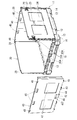
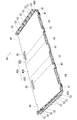
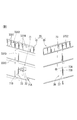
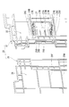
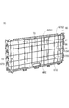
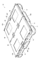
- the perspective view of the box pallet which concerns on one Embodiment of this invention A perspective view of the box pallet with one second pallet side wall removed.
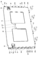
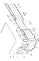
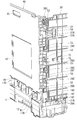
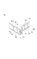
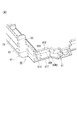
- Perspective view of first pallet side wall The perspective view of the lower end part of a 1st pallet side wall, and a rotation support part
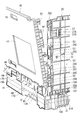
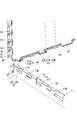
- the perspective view of the state which made the 2nd pallet side wall slanted on the insertion support part The perspective view of the state which contacted the 2nd pallet side wall with the upper surface of the insertion support part Partially broken perspective view of the box pallet in a state where the upward engagement hook and the downward engagement hook are engaged.
- positioned at the one end side of a slider receiving part The perspective view of the coupling slider arrange
- Front side perspective view of coupling slider Perspective view of the back side of the coupling slider Partially cutaway perspective view of a combined slider disposed on one end side of the slider receiving portion Partially broken perspective view of a combined slider arranged on the other end side of the slider receiving portion
- the box pallet 10 of this embodiment is formed by assembling a pair of first pallet side walls 20, 20 and a pair of second pallet side walls 40, 40 to a pallet body 11.
- the pallet main body 11 has a substantially rectangular parallelepiped shape that is flat in the vertical direction, and is provided with a fork insertion hole 12 for inserting a fork of a forklift in a penetrating state in both vertical and horizontal directions.
- the lower surface of the pallet body 11 has a stacking contact portion 13 with the outer edge portion shifted upward in a stepped shape.
- a pair of trapezoidal lower surface positioning protrusions 14 and 14 are formed to protrude at each corner of the stacked contact portion 13 at two positions sandwiching the apex of each corner.
- a side wall support 15 projects from the outer edge of the top surface of the pallet body 11.
- a pair of rotation support portions 15A and 15A arranged on a pair of opposite sides of the side wall support portion 15 is higher than the upper surface of the pallet main body 11 by the thickness of one first pallet side wall 20,
- the pair of insertion support portions 15B and 15B located on the remaining pair of opposite sides is more than the rotation support portion 15A by the thickness of the first pallet side wall 20 and the second pallet side wall 40, one by one. It is high.
- the pair of first pallet side walls 20 and 20 are rotatably assembled to the pair of rotation support portions 15A and 15A, and the pair of second pallet side walls 40 and 40 is a pair of insertion support portions. It is assembled
- first pallet side wall 20 and the second pallet side wall 40 correspond to the “box pallet side wall” of the present invention, and both form a hollow structure.
- first pallet side wall 20 will be described in detail with respect to the detailed structure other than the internal structure
- second pallet side wall 40 will be described in detail with respect to the detailed structure other than the internal structure
- first pallet side wall 20 and the second pallet side wall 20 will be described.
- the internal structure of the pallet side wall 40 will be described in detail.
- the “outer surface of the first pallet side wall 20” does not indicate an outer surface with respect to the inner surface of the hollow structure of the first pallet side wall 20 but is the first of the box pallets 10. The surface outside the luggage storage space surrounded by the first pallet side wall 20 and the second pallet side wall 40 is indicated. Further, “the inner surface of the first pallet side wall 20” does not indicate the inner surface of the hollow structure of the first pallet side wall 20 but is surrounded by the first pallet side wall 20 and the second pallet side wall 40 in the box pallet 10. The inner surface facing the designated luggage storage space. The same applies to the second pallet side wall 40.
- the first pallet side wall 20 is a horizontally long rectangle, and includes a plurality of hinge protrusions 21 on the lower surface.
- the plurality of hinge protrusions 21 include a rotation shaft portion 21B at the tip of a protruding base portion 21A protruding downward from the lower surface of the first pallet side wall 20.
- the protruding base portion 21A is wide in the longitudinal direction of the lower surface of the first pallet side wall 20, and both end portions of the rotating shaft portion 21B are on both sides from both side surfaces of the protruding base portion 21A in the wide direction. It protrudes toward.
- the rotating shaft portion 21B is flat in the vertical direction, and the surface of the rotating shaft portion 21B facing outward in the thickness direction of the first pallet side wall 20 is curved, and the opposite surface and the upper and lower surfaces are curved. Both sides are flat.
- a plurality of rotation support recesses 16 are recessed in the rotation support portion 15 ⁇ / b> A of the pallet body 11 with respect to the plurality of hinge protrusions 21 of the first pallet side wall 20.
- the rotation support recess 16 opens to the upper surface and the inner surface of the rotation support portion 15A.
- the upper surface opening 16 ⁇ / b> A of the rotation support recess 16 has substantially the same size as the planar shape of the hinge protrusion 21, and the side opening 16 ⁇ / b> B of the rotation support recess 16 has substantially the same width as the protrusion base 21 ⁇ / b> A in the hinge protrusion 21. There is no.
- the retaining projections 16T and 16T (only one retaining projection 16T is shown in FIG. 4) on both sides of the side opening 16B of the rotation support recess 16. ) Is provided.
- the first pallet side wall 20 is in a state where the first pallet side wall 20 is tilted horizontally, and the rotation shaft portion 21B is between the retaining protrusions 16T and 16T and the inner surface of the rotation support recess 16 facing them. Inserted into. Then, when the first pallet side wall 20 is rotated upward with the rotation shaft portion 21B as a fulcrum and is raised on the rotation support portion 15A (see FIG. 2), the rotation shaft portion 21B is below the retaining projection 16T. (See FIG. 7), the hinge protrusion 21 is prevented from being detached from the rotation support recess 16. Thus, the 1st pallet side wall 20 is connected with the rotation support part 15A so that rotation is possible.
- a central protrusion 22 is provided at the center in the longitudinal direction on the lower surface of the first pallet side wall 20.
- the central protrusion 22 has a shape in which the rotation shaft 21 ⁇ / b> B is excluded from the hinge protrusion 21 described above.
- a center recess 16 ⁇ / b> C is formed in the rotation support portion 15 ⁇ / b> A of the pallet body 11.
- the central recess 16C opens at the same width as the central protrusion 22 on the upper surface and the inner surface of the rotation support portion 15A. And the center protrusion 22 is received in the center recessed part 16C, and the horizontal movement of the 1st pallet side wall 20 is controlled.
- a rotation restricting projection wall 16D protrudes from the insertion support portion 15B above both ends of the turn support portion 15A (FIG. 4 shows only one rotation restricting projection wall 16D. It is shown). Further, the lower end portion of the rotation restricting projection wall 16D is recessed into a stepped shape on the insertion support portion 15B side to form a locking recess 16E. And when the 1st pallet side wall 20 was made into the standing posture, as shown in FIG. 6, the lower part of the both-sides edge part of the 1st pallet side wall 20 contact
- a handle portion 23 is recessed and formed at the center of the upper edge portion.
- the handle portion 23 is formed in a horizontally long rectangle, and has a shape provided with a protruding piece 23T at the lower end opening edge thereof.
- the projecting piece 23T is flush with the outer surface of the first pallet side wall 20 and projects to the inner side of the opening of the handle portion 23.
- Outer surface depressions 24 and 24 are provided on both sides of the handle portion 23 of the outer surface of the first pallet side wall 20 so that the outer surface of the first pallet side wall 20 is slightly depressed.
- the outer surface depression 24 has a quadrangular shape, ranging from the upper position to the lower position in the first pallet side wall 20 in the vertical direction, and from the center of the first pallet side wall 20 to the side position in the left and right direction. It is formed in a wide range.
- the first pallet side wall 20 is formed with side step recesses 25 and 25 by recessing both side edges of the outer surface with a constant width.
- a first side projection 26A is provided at the lower end of each side step recess 25, and a second side projection 26B is provided thereabove.
- 26 A of 1st side surface protrusions have comprised the structure which provided the taper surface in the upper side corner
- the second side protrusion 26B has a rectangular parallelepiped shape integrated with the step surface 25A and the back surface 25B of the side step recess 25.
- the first side protrusion 26A causes the tapered surface to slide in contact with the lower part of the rotation restricting protrusion 16D, and the locking recess 16E.
- the first side projection 26A and the second side projection 26B are fitted and engaged, and the rotation regulating projection wall 16D is sandwiched in the vertical direction, so that the upper and lower sides of the first pallet side wall 20 with respect to the pallet body 11 Restrict movement.
- a plurality of upward engagement hooks 26 ⁇ / b> C are arranged in the vertical direction above the second side protrusion 26 ⁇ / b> B in the side step recess 25.
- Each upward engagement hook 26C is integrally continuous with the step surface 25A and the back surface 25B of the side step recess 25, protrudes laterally from the step surface 25A, and has a tip bent upward. It has become.
- the induction taper surface 26T is formed only in the upward engagement hook 26C at the lowermost end.
- the guide taper surface 26T is formed by cutting the upper end portion of the upward engagement hook 26C obliquely (for example, 45 degrees) with respect to the vertical direction, and is inclined so as to be separated from the step surface 25A as it goes downward.
- the uppermost upper engaging hook 26C is disposed at the upper end of the side step recess 25, and the distance between the uppermost upper engaging hook 26C and the second upper engaging hook 26C from the top is as follows. It is wider than the interval between the other adjacent upward engaging hooks 26C.
- a step surface opening 28A is provided on the step surface 25A between the uppermost portion and the next upward engagement hooks 26C, 26C, and the tip of the coupling slider 27 protrudes and protrudes from the step surface opening 28A. Yes.
- slider receiving portions 28 are recessed at positions near the upper corners of the first pallet side wall 20.
- each slider receiving portion 28 has a substantially rectangular outer surface opening 28B on the outer surface of the first pallet side wall 20, and a guide hole 28D communicating with the step surface 25A of the side step recess 25.
- the end of the guide hole 28D is opened at the step surface 25A to form a step surface opening 28A.
- a slide locking piece 28C is projected inward from the upper and lower opening edges of the outer surface opening 28B (only one slide locking piece 28C is shown in FIG. 9A).
- the back surface 28 ⁇ / b> E of the slider receiving portion 28 is provided with a guide protrusion 28 ⁇ / b> F extending in the horizontal direction.
- the coupling slider 27 is provided with a box-shaped operation unit 27A having a structure in which a vertically long rectangular plate 27C is surrounded by a rectangular tube wall 27D.
- the coupling slider 27 is received by the slider receiving portion 28 in a state where the rectangular plate 27C of the box-shaped operation portion 27A and the back surface 28E of the slider receiving portion 28 are opposed to each other.
- slide locking protrusions 27E and 27E are projected from both upper and lower side surfaces of the box-shaped operation portion 27A, and these slide locking protrusions 27E and 27E are shown in FIG.
- the slide engaging pieces 28C and 28C of the slider receiving portion 28 are engaged with the back surfaces.
- the coupling slider 27 is prevented from coming off in the slider receiving portion 28.
- the tips of the slide locking protrusions 27E and 27E are abutted against the upper and lower inner surfaces of the slider receiving portion 28, whereby the coupling slider 27 is supported in the slider receiving portion 28 so as not to move up and down.
- an engagement groove 27M that engages with a guide protrusion 28F (see FIG. 9B) of the slider receiving portion 28 is formed at one end of the box-shaped operation portion 27A.
- the coupling slider 27 is located with respect to the first pallet side wall 20 within the range of the difference in lateral width between the box-shaped operation portion 27 ⁇ / b> A and the outer surface opening 28 ⁇ / b> B of the slider receiving portion 28. Directly move left and right.
- a protruding piece 27B protrudes from one side surface of the box-shaped operating portion 27A toward the guide hole 28D of the slider receiving portion 28.
- the coupling slider 27 is arranged at the release position at one end of the movable range, as shown in FIG. 11A, the rush piece 27B is accommodated in the guide hole 28D and does not project from the stepped surface opening 28A.
- the tip of the entry piece 27B protrudes outward from the step surface opening 28A.
- the engagement protrusion 27B is formed with a gate-shaped slit 27G at the center in the width direction, and the inside of the slit 27G is an elastic locking piece 27H.
- a locking projection 27J protrudes from the outer end surface of the elastic locking piece 27H.
- a locking step 28G is formed on the inner surface of the guide hole 28D, and when the coupling slider 27 is disposed at the side wall coupling position, as shown in FIG. The locking protrusion 27J of the stop piece 27H is locked to the locking step portion 28G.
- the second pallet side wall 40 is a horizontally long rectangle, and includes first to fourth insertion protrusions 41, 42, 43, 44 on the lower surface.
- the first insertion protrusions 41 are disposed at positions closer to both ends in the longitudinal direction on the lower surface of the second pallet side wall 40, and the second insertion protrusions 42 are located at the longitudinal center of the lower surface of the second pallet side wall 40.
- the third insertion protrusion 43 is disposed at an intermediate position between each of the first insertion protrusions 41 and the second insertion protrusions 42, and the fourth insertion protrusions 44 are adjacent to each other. 1 and the third insertion protrusions 41 and 43 and between the adjacent second and third insertion protrusions 42 and 43, respectively.
- the first insertion protrusion 41 When viewed from the thickness direction of the second pallet side wall 40, the first insertion protrusion 41 has the protrusion 41B from the lower surface of the trapezoidal base 41A narrowed downward as shown in FIG. It has a protruding shape. Moreover, the 2nd insertion protrusion 42 is a horizontally long rectangle. Moreover, the 3rd insertion protrusion 43 has the shape which protruded the latching protrusions 43B and 43B from the lower end both sides
- the insertion support portion 15B of the pallet main body 11 has the first to fourth receiving recesses 17A. , 17B, 17C, and 17D.
- the first to fourth receiving recesses 17A, 17B, 17C, and 17D are recessed with respect to both the upper surface and the inner surface of the insertion support portion 15B.
- the side surface opening 17F located on the inner side surface of the insertion support portion 15B is more than the upper surface opening 17E located on the upper surface of the insertion support portion 15B. It is narrow and only the base 43A of the third insertion protrusion 43 can pass through the side opening 17F.
- the second pallet side wall 40 is erected on the insertion support portion 15B, and the first to fourth insertion protrusions 41, 42, 43, and 44 are moved to the first to fourth.
- the receiving recesses 17A, 17B, 17C, and 17D can be inserted.
- the lower end part of the 2nd pallet side wall 40 is hold
- the latching protrusion 43B of the third insertion protrusion 43 is moved.
- the second pallet side wall 40 is horizontally inserted by inserting the base 43A of the third insertion protrusion 43 into the side opening 17F of the third receiving recess 17C while being inserted into the inside from the upper surface opening 17E of the third receiving recess 17C. Holds immovable.
- the first, second, and fourth insertion protrusions 41, 42, and 44 are connected to the inner surface of the insertion support portion 15B with respect to the first, second, and fourth receiving recesses 17A, 17B, and 17D. It will be received through the side opening.
- an outer lower end handle portion 46 is recessed in the outer surface of the second pallet side wall 40 at the center of the lower end portion.
- the outer surface lower end handle portion 46 has the same shape as the handle portion 23 of the first pallet side wall 20 described above, and includes a projecting piece 46T at the lower end opening edge.
- a pair of laterally rectangular upper surface upper-end hand-clamping recesses 45, 45 are formed in the upper edge portion on the outer surface of the second pallet side wall 40 so as to be recessed side by side.
- a pair of inner-surface upper-end hand-clamping recesses 48, 48 each having a horizontally long rectangle are formed side by side along the edge.
- Outer surfaces of the second pallet side wall 40 are provided on both sides of the outer surface lower end handle 46 with outer surface recessed portions 47 and 47 in which the outer surface of the second pallet side wall 40 is slightly recessed.
- the outer surface depression 47 has a quadrangular shape and extends in the vertical direction from the position near the lower end of the second pallet side wall 40 to the position near the center, and in the left-right direction extends from the center of the second pallet side wall 40 to the position near the side. Formed in the range.
- the central portion in the left-right direction on the inner surface of the second pallet side wall 40 is a slightly depressed central depressed portion 40A.
- the central depressed portion 40A has a shape including gently inclined surfaces 40C and 40C on both sides of a depressed bottom surface 40B extending at a constant width over the entire vertical direction of the second pallet side wall 40.
- Step portions 40D and 40D are formed at the lower ends of both side edge portions of the second pallet side wall 40, and the upper side portions of the step portions 40D and 40D are side edges projecting laterally from the lower side portion of the step portion 40D.
- the side cover walls 51 protrude vertically from the outer edge portions of the side edge connection base portions 50 on the inner surface of the second pallet side wall 40.
- a plurality of downward engagement hooks 53 are provided side by side along the inner corners of the side cover wall 51 and the side edge connection base 50. These downward engaging hooks 53 are integrally connected to the side edge connection base 50 and the side cover wall 51, protrude in the same direction as the side cover wall 51 of the side edge connection base 50, and the tip thereof is downward.
- a side lower end wall 52 protruding in the same direction as the side cover wall 51 is provided at the lower end of the side edge connecting base 50, and the side edge connecting base 50 and the side The lower ends of the cover wall 51 are in communication with each other.
- the side lower end wall 52 is the second pallet side wall 20. It is placed on the side protrusion 26B.
- the second pallet side wall 40 is integrally provided with an engagement box portion 54B on the upper side of the second downward engagement hook 53 from the top, and the inside of the engagement box portion 54B is The engaging recess 54 is open toward the first pallet side wall 20. Then, the engaging protrusion 27B (see FIG. 9B) of the coupling slider 27 on the first pallet side wall 20 enters the engaging recess 54, and the upward movement of the second pallet side wall 40 relative to the first pallet side wall 20 is restricted. Is done.
- a peep hole 55 communicating with the engagement recess 54 is formed on the outer surface of the side cover wall 51. Further, the coupling slider 27 has a color different from that of the second pallet side wall 40. Then, through this peep hole 55, it can be visually confirmed whether or not the engagement protrusion 27B is engaged in the engagement recess 54.
- upper surface positioning recesses 49 and 49 are recessed at both ends of the upper surface of the second pallet side wall 40.
- upper surface positioning recesses 29 and 29 are recessed at both ends of the upper surface of the first pallet side wall 20. 29, when another box pallet 10 is stacked on the box pallet 10 in a state where the first pallet side wall 20 and the second pallet side wall 40 are erected, the lower surface of the upper box pallet 10 The positioning protrusion 14 is fitted into the upper surface positioning recesses 29 and 49.
- the first pallet side wall 20 and the second pallet side wall 40 both correspond to the “box pallet side wall” of the present invention and have a hollow structure.
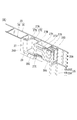
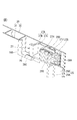
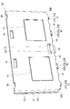
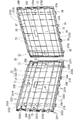
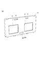
- the first pallet side wall 20 is formed by fixing the outer configuration board 31 and the inner configuration board 35 shown in FIGS. 17 and 18, and the second pallet side wall 40 is formed by using FIGS.
- the outer configuration board 61 shown in 24B and the inner construction board 65 shown in FIGS. 25A and 25B are fixed to each other.
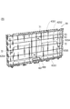
- the first pallet side wall 20 includes an outer main plate 32 and an inner main plate 36 facing each other with the sealed space 20 ⁇ / b> P interposed therebetween.
- a resin fixing layer 20K is provided between the outer main plate 32 and the inner main plate 36 along a surface that divides the entire first pallet side wall 20 into two in the thickness direction.
- the fixing layer 20 ⁇ / b> K is disposed near the inner main plate 36 in the thickness direction of the first pallet side wall 20.
- the outer main plate 32 side of the first pallet side wall 20 from the fixed layer 20K is the outer component plate 31, and the inner main plate 36 side of the first pallet side wall 20 from the fixed layer 20K is the inner component plate 35. Yes.
- the outer configuration board 31 has a structure in which cell configuration ribs 33 are stretched around the entire surface of the outer main plate 32 facing the inner main plate 36.
- the inner component board 35 has a structure in which cell constituting ribs 37 are stretched around a surface of the inner main plate 36 facing the outer component board 31.
- the cell constituting ribs 33 of the outer constituting board 31 are in a lattice shape, and the grid of the frame-like area cell 33S1 in the frame-like area along the outer edge of the outer constituting board 31 is a central area inside the frame-like area.
- the cell constituting rib 33 includes a plurality of long horizontal ribs 33 ⁇ / b> X extending over substantially the entire lateral direction of the first pallet side wall 20 and substantially the entire longitudinal direction of the first pallet side wall 20.
- a plurality of elongated vertical ribs 33Y are included.
- the distance between the two upper edge long horizontal ribs 33X1 and 33X1 in the upper edge region of the first pallet side wall 20, and the two lower edge lengths in the lower edge region
- the distance between the horizontal ribs 33X2 and 33X2 is the distance between the central long horizontal ribs 33X3 and 33X3 (see FIG. 17) provided in the central area between the upper edge area and the lower edge area. It is narrower than that.
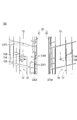
- long vertical ribs 33Y for example, three or more side edge long vertical ribs 33Y1 (see FIG. 21A) in the side edge regions on both sides of the first pallet sidewall 20 are spaced between the side edge regions. This is narrower than the interval between the central long vertical ribs 33Y3, 33Y3 provided in the central region.
- a plurality of edge reinforcements are provided in each of the meshes partitioned by the plurality of central long vertical ribs 33Y3 between the upper edge long horizontal ribs 33X1, 33X1 and between the lower edge long horizontal ribs 33X2, 33X2.
- the vertical rib 33Y4 is provided in parallel with the central long vertical rib 33Y3, and a plurality of upper edge region cells 33S2 and lower edge region cells 33S3 are configured.
- a plurality of edge reinforcing horizontal ribs 33X4 are parallel to the central long horizontal ribs 33X3 in each of the cells partitioned by the plurality of central long horizontal ribs 33X3 among the side edge long horizontal ribs 33Y1, 33Y1.
- a plurality of side edge region cells 33S4 are formed.
- the upper edge area cell 33S2, the lower edge area cell 33S3, and the both side areas 33S4 and 33S4 constitute a frame-like area cell 33S1, and the grid of these frame-like area cells 33S1 is the central long side of the central area. It is finer than the grid of the central area cell 33S5 partitioned by the rib 33X3 and the central long vertical rib 33Y3.
- the cell constituent ribs 37 of the inner constituent board 35 are also formed in a lattice shape like the cell constituent ribs 33 of the outer constituent board 31, and the frame shape in the frame-like region along the outer edge of the inner constituent board 35.
- the grid of the cell 37S1 is finer than the grid of the central region cell 37S5 in the central region. Then, the tips of the cell constituting ribs 33 of the outer constituting board 31 and the cell constituting ribs 37 of the inner constituting board 35 are fixed to each other, and the outer main plate 32 and the inner main plate 36 are connected by the cell constituting ribs 33 and 37.
- the sealed space 20P in the first pallet side wall 20 is partitioned into a plurality of cells (small rooms) 20S by the cell constituting ribs 33 and 37 (see FIG. 19).
- the outer component panel 31 and the inner component panel 35 are fixed by, for example, heat welding.
- the outer component panel 31 and the inner component panel 35 are disposed between a pair of opposed jigs (not shown) in a state where the outer component panel 31 and the inner component panel 35 are joined.
- the outer component board 31 and the inner component board 35 are clamped by a pair of opposing jigs, and the outer component board 31 and the inner component board 35 are separately fixed to the opposing jigs.
- the outer configuration board 31 and the inner configuration board 35 are separated. In this state, a heated iron plate is disposed between the outer component panel 31 and the inner component panel 35.
- the first pallet side wall 20 of the present embodiment is shown in FIG. 17 in order to position and join the outer component board 31 and the inner component board 35 to each other before being fixed to the pair of opposing jigs.
- the outer configuration board 31 is provided with a lateral position determination section 71 and a vertical direction positioning section 72
- the inner configuration board 35 is provided with a positioning fitting projection 73.
- the lateral position determining unit 71 is for positioning and fixing the outer component board 31 and the inner component board 35 to each other in the lateral direction. It is arranged at two locations, a position closer to the upper end and a position closer to the lower end in the approximate center of the direction.
- the vertical position determining unit 72 is for positioning and fixing the outer component board 31 and the inner component board 35 to each other in the vertical direction. It is arrange
- the positioning fitting protrusion 73 is arrange
- the lateral positioning part 71 has a shape obtained by rotating the longitudinal positioning unit 72 by 90 degrees, and a pair of opposed pieces 71A opposed to each other in the lateral direction of the outer component board 31.
- the positioning fitting protrusion 73 has a “+” cross section, and the first protruding piece 73A having a thickness direction in the vertical direction of the inner component board 35 and a thickness direction in the horizontal direction.
- the second entry pieces 73B facing each other are crossed at the center in the width direction. Further, both corners of the tips of the first and second entry pieces 73A and 73B are chamfered.
- the above-described lateral direction positioning portion 71 and vertical direction positioning portion 72 are higher than the cell configuration rib 33, and the positioning fitting protrusion 73. Is higher than the cell constituting rib 37. Then, when the outer component board 31 and the inner component board 35 before being fixed to the pair of opposed jigs are joined to each other, the positioning fitting protrusions are formed between the opposing pieces 72A and 72A of the vertical positioning part 72. The portion 73 is fitted and the outer component board 31 and the inner component board 35 are positioned in the vertical direction, and the positioning fitting projection 73 is fitted between the opposing pieces 71A and 71A of the lateral position determining unit 71.
- the outer component board 31 and the inner component board 35 are positioned in the lateral direction. Then, the lateral positioning unit 71, the vertical positioning unit 72, and the positioning fitting protrusion 73 are heated after the outer component panel 31 and the inner component panel 35 are fixed to a pair of opposing jigs. The tip is melted by being pressed against the iron plate to be welded, and is lowered to the same height as the cell constituting rib 33 or the cell constituting rib 37.
- the horizontal direction is maintained in a state where the tip is not melted.
- the positioning portion 71, the vertical positioning portion 72 and the positioning fitting protrusion 73 can be left in the first pallet side wall 20.
- a horizontally long rectangular through hole serving as the opening of the above-described handle portion 23 (see FIG. 3) is formed.
- the square tube 23B protrudes from the edge of the.
- a horizontally elongated rectangular rib 23C corresponding to the rectangular tube 23B is provided in the central region of the inner main plate 36.
- the annular rib 23C adheres to the front-end
- a substantially square outer surface opening 28B in the slider receiving portion 28 (see FIG.
- the inner main plate 36 is provided with a frame-shaped rib 28W corresponding to the frame wall 28V. Then, a frame-like rib 28W is fixed to the tip of the frame wall 28V to form an inner wall of the slider receiving portion 28 (see FIG. 9B).
- the above-described central protrusion 22 is divided into two at a position near the inner main plate 36 by the fixing layer 20K. Further, the above-described hinge protrusion 21 is divided into two at the position closer to the inner main plate 36 by the fixing layer 20K, and the rotation shaft portion 21B is formed on the outer component board 31 side without being divided into two. .
- the inner main plate 36 side of the fixed layer 20 ⁇ / b> K is constituted by a plurality of lower end protrusions 39 projecting downward from the lower end of the inner component board 35.
- the outer main plate 32 side of the protruding base 21A from the fixed layer 20K is configured by a lower end block 34A protruding from the lower surface of the outer component board 31, and the outer main plate 32 side of the central protrusion 22 from the fixed layer 20K is The lower end block 34B protrudes from the lower surface of the outer component board 31.
- hinge reinforcing ribs 37 ⁇ / b> A which are part of the cell constituting ribs 37, are arranged on the respective lower end projecting pieces 39 at positions shifted inward from the tip and side ends.
- the lower edge long horizontal rib 37X2 extending in the horizontal direction at the lower end portion of the inner component board 35 is arranged slightly shifted from the lower end of the inner main plate 36.
- the part which protruded outside the hinge reinforcement rib 37A and the lower edge elongate horizontal rib 37X2 among the inner side structure board 35 is the lower end contact protrusion part 35T for forming the lower surface groove
- the lower end block 34A for the hinge protrusion 21 has the same shape as the hinge reinforcing rib 37A of the inner configuration panel 35 when viewed from the thickness direction of the outer configuration panel 31, and is rotated from the lower end surface of the lower block 34A.
- a step portion is formed with the lower end surface of the moving shaft portion 21B positioned below.
- the lower end block 34B for the central protrusion 22 has a shape in which both end portions of the rotating shaft portion 21B protruding from both side surfaces of the lower end block 34A for the hinge protrusion 21 are cut off, Has a step at the lower end.
- a lower end abutting protrusion 31T protrudes from the edge part away from the fixing layer 20K on the lower surface of the outer component board 31, and from a plurality of positions in the longitudinal direction of the lower end abutting protrusion 31T to a position near the fixing layer 20K.
- a plurality of reinforcing protrusions 31S extend.
- the lower end surfaces of the hinge projection 21 and the central projection 22 on the first pallet side wall 20 are relatively narrow as shown in FIG.
- a lower surface groove 20M1 is formed, and a relatively wide lower surface groove 20M2 is formed on the entire lower surface of the first pallet side wall 20 between the lower end contact protrusions 31T and 35T.
- the fixed layer 20K is arrange
- the lower end contact protrusion 35 ⁇ / b> T protrudes from the vicinity of the fixed layer 20 ⁇ / b> K.
- the resin melted in the outer component board 31 and the inner component board 35 is excessive resin protrusions 20J along the outer edge of the fixing layer 20K ( 23) and can protrude outward from the upper and lower surfaces and both side surfaces of the first pallet side wall 20.
- the upper surface and both side surfaces of the 1st pallet side wall 20 are comparatively flat shapes, the excess resin protrusion 20J can be easily cut off with a tool, but the lower surface of the 1st pallet side wall 20 is a hinge. Since it has a concavo-convex shape including the protrusion 21 and the central protrusion 22, the excess resin protrusion 20J cannot be easily removed with a tool.
- the surplus resin protrusions 20J on the lower surface of the first pallet side wall 20 are not cut off, and surplus is placed in the lower surface grooves 20M1 and 20M2 at the lower end of the first pallet side wall 20. Since the resin protrusions 20J are accommodated, the surplus resin protrusions 20J are prevented from coming into contact with the upper surface, floor surface, or the like of the rotation support portion 15A. As a result, it is possible to prevent a situation in which a crack occurs in the fixing layer 20K due to stress concentration caused by the load on the surplus resin protrusion 20J.
- the plurality of reinforcing protrusions 31S extend from the lower end abutting protrusion 31T to a position in the vicinity of the fixing layer 20K, so that, for example, the upper surface corner of the rotation support portion 15A is in the lower surface groove 20M2. It is possible to prevent a situation in which the rush enters the surplus resin ridge 20J.
- the second pallet side wall 40 includes an outer main plate 62 and an inner main plate 66 that are opposed to each other with the sealed space 40P interposed therebetween. Further, a resin fixing layer 40K is provided between the outer main plate 62 and the inner main plate 66 along a plane that divides the entire second pallet side wall 40 into two in the thickness direction. In addition, the fixing layer 40K is disposed at the approximate center of the second pallet side wall 40 in the thickness direction.
- One side of the second pallet side wall 40 from the fixed layer 40K is an outer component board 61 having a structure in which lattice-like cell constituting ribs 63 are stretched around the outer main plate 62, while the other side is an inner main plate.
- the inner structure board 65 has a structure in which a lattice-shaped cell structure rib 67 is stretched around 66.
- the grids of the frame-like region cells 63S1 and 67S1 in the frame-like regions along the outer edges of the outer component board 61 and the inner component board 65 are frame-shaped. It is finer than the grid of the central region cells 63S5 and 67S5 in the central region inside the region (see FIGS. 24B and 25B). And the front-end
- a lateral positioning portion 71, a longitudinal positioning portion 72, and a positioning fitting projection 73 for positioning when performing the heat welding include the outer main plate 62 and the inner main plate 62. It is provided on the opposing surface of the main plate 66.
- the outer bottom edge handle portion 46 of the second pallet side wall 40 is the same as the handle portion 23 of the first pallet side wall 20, and the square tube 46B of the outer component board 61 shown in FIG.
- the inner structure board 65 is divided into annular ribs 46 ⁇ / b> C.
- the outer surface upper-hand handle recess 45 is entirely disposed on the outer component board 61, and is formed by recessing the outer main plate 62, and the inner-surface upper-hand handle recess 48 is shown in FIG. 25A.
- the whole is disposed on the inner component board 65, and the inner main plate 66 is formed to be depressed.
- the side cover wall 51, the side lower end wall 52, the downward engagement hook 53, and the engagement recess 54 are all disposed on the inner component panel 65 side.
- the fourth insertion protrusion 44 is entirely composed of an outer component board.
- the remaining first to third insertion protrusions 41, 42, and 43 are divided into two by the fixing layer 40K.
- the base 43A and the latching protrusion 43B are divided. And are both divided into two.
- the lower end abutting protrusion 61T and the reinforcing protrusion are formed on the lower surface of the outer component board 61 as shown in FIG. 26A.
- a lower end contact protrusion 65T and a reinforcing protrusion 65S are formed to protrude on the lower surface of the inner component board 65.
- the lower end contact protrusions 61T and 65T and the reinforcing protrusions 61S and 65S are also extended to the constituent portions of the first insertion protrusion 41 in the outer component board 61 and the inner component board 65.
- the lower surface of the second pallet side wall 40 and the lower end surface and side surface of the first insertion protrusion 41 are relatively wide like the lower surface groove 20M2 of the first pallet side wall 20.
- the lower surface groove 40M2 is formed, and the fixed layer 40K is disposed on the bottom surface thereof.
- the second and third insertion protrusions 42 and 43 have a relatively narrow lower surface groove 40M1 at the tip, similar to the lower surface groove 20M1 of the first pallet side wall 20 described above. Are formed over the entire surface from both sides to the bottom surface of the lower surface groove 40M1. Thereby, even if the surplus resin protrusion is left on the lower surface of the second pallet side wall 40 in the same manner as the first pallet side wall 20, it is possible to prevent the surplus resin protrusion from being loaded.
- a part of the plurality of reinforcing protrusions 61S and 65S described above is disposed at both ends in the longitudinal direction on the lower surface of the second pallet side wall 40 (see FIG. 27A), and is particularly susceptible to impact. The bottom corner is protected.
- a part of the plurality of reinforcing protrusions 31S is also arranged at both ends in the longitudinal direction on the lower surface of the first pallet side wall 20 (see FIG. 27B).
- the outer component board 31 and the inner component board 35 on the first pallet side wall 20 have different colors
- the outer component board 61 and the inner component board on the second pallet side wall 40. 65 is a different color
- the outer component board 31 of the first pallet side wall 20 and the outer component board 61 of the second pallet side wall 40 form the same color (for example, a blue color), and the inner side of the first pallet side wall 20.
- the component board 35 and the inner component board 65 of the second pallet side wall 40 have the same color (for example, white).
- the outer component boards 31 and 61 correspond to the “outer part” of the present invention
- the inner component boards 35 and 65 correspond to the “inner part” of the present invention.
- the first pallet side walls 20 and 20 and the second pallet side walls 40 and 40 can be folded on the pallet body 11 as shown in FIG. Specifically, the paired sliders 27 are slid with respect to the assembled box pallet 10 shown in FIG. 1 to release the engagement with the engagement recesses 54 (see FIG. 8), and then the pair of first pallets.
- the pallet side walls 20 and 20 are sequentially rotated and folded on the pallet body 11 as shown in FIG.
- each upward engagement hook 26C of the first pallet side wall 20 is opposite to the side cover wall 51 with respect to each downward engagement hook 53 of the second pallet side wall 40 with which they are engaged. Since it can be moved to the side and separated, the first pallet side walls 20, 20 can be folded on the pallet body 11 without removing the second pallet side walls 40, 40.
- one second pallet side wall 40 is removed upward from the pallet body 11.
- the fingers of both hands are pulled up by pulling on the pair of outer surface upper end hand-holding recesses 45, 45 of the second pallet side wall 40 and the pair of inner surface upper end hand-holding recesses 48, 48 arranged on the back side thereof.
- the second pallet side wall 40 can be easily detached from the pallet main body 11.
- the second pallet side wall 40 is rotated to have a substantially horizontal posture, and the tip end portion (the upper end portion of the second pallet side wall 40 in the standing posture) is brought into contact with the first pallet side wall 20, and the second The base end portion of the pallet side wall 40 (the lower end portion of the second pallet side wall 40 in the standing posture) is pulled upward from the front end portion, and the latching protrusion 43B of the third insertion protrusion 43 is moved to the third receiving portion of the pallet main body 11.
- the concave portion 17C is inserted from above (see FIG. 14).
- the hooking protrusion 43B can be easily inserted into the third receiving recess 17C from above by placing a finger on the protrusion 46T of the outer surface lower end hooking part 46 in each second pallet side wall 40.
- a pair of second pallet side walls 40, 40 between the pair of insertion support portions 15B, 15B. are fitted side by side, whereby the folding operation of the box pallet 10 is completed.
- the second pallet side walls 40, 40 are first taken out from between the pair of insertion support portions 15B, 15B, contrary to the above-described operation. And attached on the insertion support portions 15B and 15B. Then, the first pallet side walls 20, 20 may be rotated to the standing posture to engage the respective coupling sliders 27 with the engagement recesses 54.
- the second pallet side wall 40 can be easily moved from between the pair of insertion support portions 15B and 15B by placing a finger on the protruding piece 46T of the outer surface lower end handle portion 46 of the second pallet side wall 40.
- the first pallet side wall 20 can be easily rotated to the standing posture by placing a finger on the protruding piece 23T of the handle portion 23 on the first pallet side wall 20.
- the box pallet 10 may be assembled by the following procedure. That is, the second pallet side walls 40, 40 are taken out from between the insertion support portions 15B, 15B, and leaned on a place (for example, a floor surface) different from the insertion support portion 15B, and the first pallet side wall 20, After turning 20 to the standing posture, the pair of second pallet side walls 40, 40, which have been leaned, may be sequentially installed on the insertion support portion 15B in the standing posture.
- the second pallet side wall 40 is divided into two different colors in the thickness direction, the front and back sides of the second pallet side wall 40 are easily discriminated when the second pallet side wall 40 is attached to the insertion support portion 15B. be able to.
- the outer component board 31 of the first pallet side wall 20 and the outer component board 61 of the second pallet side wall 40 form the same color (for example, a blue color)
- the first pallet side wall 20 and the second pallet side wall 20 have the same color.
- the insertion support part with the second pallet side wall 40 raised obliquely. What is necessary is just to rotate until it becomes a standing posture after mounting on 15B. Then, in the middle of the rotation, the lower engagement hook 53 of the lowermost end portion is in sliding contact with the guide taper surface 26T of the upper engagement hook 26C of the lowermost end portion, and each upper engagement hook 53 corresponding to each upper engagement hook 53 corresponds. It moves above the direction engagement hook 26C. If the second pallet side wall 40 is moved downward in this state, as shown in FIG. 8, each downward engagement hook 53 and each upward engagement hook 26C are engaged with each other. Therefore, the coupling slider 27 (see FIG. 9A) may be engaged with the engaging recess 54 (see FIG. 16).
- the second pallet side walls 40, 40 are removed from the pallet main body 11 before the first pallet side walls 20, 20 are folded, After the pallet side walls 20 and 20 are folded, the second pallet side walls 40 and 40 may be laid on them.
- the first pallet side wall 20 and the second pallet side wall 40 of the present embodiment corresponding to the “box pallet side wall” of the present invention have a hollow structure, and the outer main plate 32 and the inner main plate 36 facing each other, and the outer side Since the main plate 62 and the inner main plate 66 are provided, the secondary moment is increased and the strength is increased if the weight is the same as that of a conventional box pallet side wall having a solid structure. Thereby, according to the box pallet 10 of this embodiment, a heavier load than before can be conveyed.
- the 1st pallet side wall 20 and the 2nd pallet side wall 40 are sealed space 20P, 40P, the 1st pallet side wall 20 and the 2nd pallet side wall 40 do not become heavy by water immersion.
- the outer main plate 32 and the inner main plate 36, the outer main plate 62 and the inner main plate 66 are reinforced by the cell constituting ribs 33, 37, 63 and 67 which divide the sealed spaces 20P and 40P into a plurality of cells 20S and 40S. Therefore, also in this respect, higher strength and lighter weight than before can be achieved.
- the cell constituting ribs 33, 37, 63, and 67 are built in the first pallet side wall 20 and the second pallet side wall 40 and are not exposed to the outside, the first pallet side wall 20 and the second pallet side wall are provided.
- the unevenness on the outer surface of 40 can be reduced as compared with the prior art, and cleaning becomes easy and aesthetics are improved.
- the frame region cells 33S1, 37S1, 63S1, and 67S1 disposed in the frame regions of the outer edges of the first pallet sidewall 20 and the second pallet sidewall 40 are the center region cells 33S5 disposed in the center region.
- 37S5, 63S5 and 67S5 the frame-like region is strengthened by being divided more finely, so that the first pallet side wall 20 and the second pallet side wall 40 are prevented from being damaged or deformed by the fork hitting.
- the weight increase of the 1st pallet side wall 20 and the 2nd pallet side wall 40 can be suppressed compared with what refined
- the present invention is not limited to the above-described embodiment.
- the embodiments described below are also included in the technical scope of the present invention, and various other than the following can be made without departing from the scope of the invention. It can be changed and implemented.
- the cell component ribs (33, 37, 63, 67) are provided on both the outer component plate (31, 61) and the inner component plate (35, 65).
- a cell structure rib may be provided in only one of the inner structure board and the other, and the other may have a flat plate structure having no rib.
- one box pallet side wall (1st pallet side wall 20) is connected with a pallet main body so that rotation is possible, and the other box pallet side wall (2nd pallet side wall 40) is inserted in a pallet main body.
- all four box pallet side walls may be connected to the pallet main body so as to be rotatable, or all four box pallet side walls may be connected to the pallet main body.
- the central area cell 33S1 in which the frame area cells 33S1, 37S1, 63S1, and 67S1 of the entire outer edge frame area in the first pallet side wall 20 and the second pallet side wall 40 are arranged in the central area.
- the upper edge region cells 33S2, 37S2, 63S2, and 67S2 corresponding to the upper side portion of the frame-like region are limited to the central region cell 33S1, the central region.
- the side edge area cells 33S4, 37S4, 63S4, and 67S4 of the side edge area corresponding to the both side portions of the frame-like area may be divided into the central area cell 33S1 of the central area.
- 37S1, 63S1, 67S1 may be divided more finely.
- Box pallet 11 Pallet body 12 Fork insertion hole 20 First pallet side wall (box pallet side wall) 20J Surplus resin protrusion 20K, 40K Adhering layer 20M1, 20M2, 40M1, 40M2 Bottom groove 20P, 40P Sealed space 31S, 61S, 65S Reinforcement protrusion 32, 62 Outer main plate 33, 37, 63, 67 Cell component rib 33S1, 37S1, 63S1, 67S1 Frame-like area cell 33S2, 37S2, 63S2, 67S2 Upper edge area cell 33S4, 37S4, 63S4, 67S4 Side edge area cell 33S5, 37S5, 63S5, 67S5 Central area cell 36, 66 Inner main plate 40 Second Pallet side wall (box pallet side wall)
Landscapes
- Engineering & Computer Science (AREA)
- Mechanical Engineering (AREA)
- Pallets (AREA)
- Rigid Containers With Two Or More Constituent Elements (AREA)
Priority Applications (3)
| Application Number | Priority Date | Filing Date | Title |
|---|---|---|---|
| CN201280018619.4A CN103476680B (zh) | 2011-04-15 | 2012-02-06 | 箱形托盘侧壁 |
| US14/006,393 US9242761B2 (en) | 2011-04-15 | 2012-02-06 | Box pallet side wall |
| EP12771741.1A EP2684809B1 (de) | 2011-04-15 | 2012-02-06 | Seitenwand eines palettenbehälters |
Applications Claiming Priority (2)
| Application Number | Priority Date | Filing Date | Title |
|---|---|---|---|
| JP2011-091210 | 2011-04-15 | ||
| JP2011091210A JP5627532B2 (ja) | 2011-04-15 | 2011-04-15 | ボックスパレット及びボックスパレット側壁 |
Publications (1)
| Publication Number | Publication Date |
|---|---|
| WO2012140941A1 true WO2012140941A1 (ja) | 2012-10-18 |
Family
ID=47009125
Family Applications (1)
| Application Number | Title | Priority Date | Filing Date |
|---|---|---|---|
| PCT/JP2012/052638 Ceased WO2012140941A1 (ja) | 2011-04-15 | 2012-02-06 | ボックスパレット側壁 |
Country Status (6)
| Country | Link |
|---|---|
| US (1) | US9242761B2 (de) |
| EP (1) | EP2684809B1 (de) |
| JP (1) | JP5627532B2 (de) |
| CN (1) | CN103476680B (de) |
| PL (1) | PL2684809T3 (de) |
| WO (1) | WO2012140941A1 (de) |
Cited By (3)
| Publication number | Priority date | Publication date | Assignee | Title |
|---|---|---|---|---|
| JP2014162555A (ja) * | 2013-02-28 | 2014-09-08 | Sanko Co Ltd | ボックスパレット |
| WO2014186269A1 (en) | 2013-05-13 | 2014-11-20 | Macro Plastics, Inc. | Shipping container and safety catch therefor |
| EP2845818A1 (de) * | 2013-09-09 | 2015-03-11 | Orbis Corporation | Schüttgutbehälter mit ineinandergreifenden Elementen zum Stapeln |
Families Citing this family (23)
| Publication number | Priority date | Publication date | Assignee | Title |
|---|---|---|---|---|
| JP5627532B2 (ja) * | 2011-04-15 | 2014-11-19 | 三甲株式会社 | ボックスパレット及びボックスパレット側壁 |
| JP6121751B2 (ja) * | 2013-02-28 | 2017-04-26 | 三甲株式会社 | ボックスパレット |
| DE202014102216U1 (de) | 2014-05-12 | 2014-07-18 | Wi-sales GmbH | Behälter mit geschlossenen Wänden |
| CN104163295B (zh) * | 2014-07-22 | 2017-02-15 | 上海鸿研物流技术有限公司 | 可折叠容器 |
| IL237267B (en) * | 2015-02-16 | 2019-08-29 | Dolav Plastic Products Cooperative Soc Ltd | Collapsible container for high loads |
| JP6615476B2 (ja) * | 2015-04-06 | 2019-12-04 | 三甲株式会社 | 折り畳み容器 |
| CN105819064B (zh) | 2016-04-19 | 2018-10-12 | 上海鸿研物流技术有限公司 | 可折叠容器 |
| US10457444B2 (en) | 2016-05-24 | 2019-10-29 | Orbis Corporation | Bulk container with interlocking features |
| ITUA20164692A1 (it) * | 2016-06-27 | 2017-12-27 | Seko Spa | Scaffale pieghevole per stoccaggio |
| TWI751182B (zh) * | 2016-08-19 | 2022-01-01 | 美商陶氏全球科技有限責任公司 | 封裝組構及將袋裝貨物之一或多個堆疊緊固在一集裝架上之方法 |
| US10065763B2 (en) | 2016-09-15 | 2018-09-04 | Arena Packaging, Llc | Wall latching system |
| CN108860932B (zh) * | 2017-05-16 | 2024-07-30 | 中国国际海运集装箱(集团)股份有限公司 | 托盘箱 |
| JP7069770B2 (ja) * | 2018-02-06 | 2022-05-18 | 大日本印刷株式会社 | パネル容器および運搬用台車 |
| KR102015378B1 (ko) * | 2018-10-17 | 2019-08-28 | 엔피씨(주) | 측벽 분리가 가능한 상자 |
| TWI699314B (zh) * | 2019-10-18 | 2020-07-21 | 樹德企業股份有限公司 | 側開式收納箱 |
| US11891236B2 (en) | 2020-02-25 | 2024-02-06 | Pvpallet, Inc. | Transport container |
| BE1028964B1 (nl) * | 2020-12-29 | 2022-08-08 | Best Fence Bv | Een inrichting voor het ondersteunen van buizen |
| US11084623B1 (en) * | 2021-03-23 | 2021-08-10 | David Ankele | Trackable nylon pallet and collapsible container |
| JP7761923B2 (ja) * | 2021-06-17 | 2025-10-29 | 岐阜プラスチック工業株式会社 | 容器 |
| JP7710675B2 (ja) * | 2021-07-26 | 2025-07-22 | 三甲株式会社 | 搬送器具 |
| CN113800080B (zh) * | 2021-09-13 | 2024-12-13 | 大连中集物流装备有限公司 | 托盘箱 |
| BE1030517B1 (nl) * | 2022-05-12 | 2023-12-11 | Conteyor Int Nv | Opvouwbare container met plank en werkwijze voor het vouwen van de opvouwbare container |
| CN116280593A (zh) * | 2023-03-14 | 2023-06-23 | 镇江合立精宏包装科技有限公司 | 一种方便折叠且结构强度高的可重复使用的瓦楞纸箱 |
Citations (3)
| Publication number | Priority date | Publication date | Assignee | Title |
|---|---|---|---|---|
| JPH04327170A (ja) | 1990-11-13 | 1992-11-16 | Buckhorn Material Handling Group Inc | 組立式積荷コンテナ |
| JP3084649U (ja) * | 2001-09-12 | 2002-03-29 | 東邦シートフレーム株式会社 | ボックス型パレットの側面パネル |
| JP2010105731A (ja) * | 2008-10-31 | 2010-05-13 | Kyoraku Co Ltd | 樹脂製パレット |
Family Cites Families (19)
| Publication number | Priority date | Publication date | Assignee | Title |
|---|---|---|---|---|
| US3857342A (en) * | 1973-06-27 | 1974-12-31 | Loechner J | Modular nestable pallet |
| US4456142A (en) * | 1980-12-10 | 1984-06-26 | Acmil Plastic Products Pty. Ltd. | Container |
| DE3500427A1 (de) | 1985-01-09 | 1986-07-10 | Wolfgang Uwe 4444 Bad Bentheim Friedrich | Zusammenklappbarer transportkasten |
| US5168621A (en) | 1988-07-12 | 1992-12-08 | Whirlpool Corporation | Method of manufacturing a domestic appliance |
| JP2585130B2 (ja) * | 1990-07-11 | 1997-02-26 | 株式会社ダイフク | 合成樹脂製パレットの製造方法 |
| US5160029A (en) * | 1990-11-16 | 1992-11-03 | Nucon Corporation | Unitary top frame |
| DE69332255T2 (de) * | 1992-05-08 | 2003-01-02 | Fuji Photo Film Co., Ltd. | Verpackungen für photographische Filme |
| US5531352A (en) * | 1993-07-09 | 1996-07-02 | Kradon, Inc. | Agricultural container |
| US6161715A (en) * | 1998-11-05 | 2000-12-19 | Stolzman; Michael D. | Plastic pallet bin |
| US6021916A (en) * | 1998-11-05 | 2000-02-08 | Stolzman; Michael D. | Plastic pallet bin |
| SE515492C2 (sv) * | 1999-12-28 | 2001-08-13 | Arca Systems Ab | Fällbar bulkcontainer varslock försetts med profiler som minska liners rörelse relativt containern |
| SE520413C2 (sv) * | 2001-09-19 | 2003-07-08 | Arca Systems Ab | Bulkcontainer |
| CA2543168C (en) * | 2003-10-23 | 2013-09-24 | Mauser-Werke Gmbh & Co. Kg | Method for producing electrostatically non-chargeable and/or electric charge-draining plastic containers and a plastic container produced according to the method |
| BRPI0509009A (pt) * | 2004-04-19 | 2007-08-07 | Polymer Logistics Israel Ltd | container com paredes basculantes armazenadas na base e método de emprego de tal container |
| US7829165B2 (en) * | 2005-11-16 | 2010-11-09 | Ridge Corporation | Trailer wall composite liner with integral scuff panel |
| US20080169285A1 (en) * | 2007-01-16 | 2008-07-17 | Nick Marazita | Collapsible container |
| CA2717517C (en) * | 2009-10-26 | 2017-11-28 | Magna International Inc. | Shipping pallet post reinforcement |
| DE202010000856U1 (de) * | 2010-01-13 | 2010-04-08 | Schoeller Arca Systems Gmbh | Großladungsträger |
| JP5627532B2 (ja) * | 2011-04-15 | 2014-11-19 | 三甲株式会社 | ボックスパレット及びボックスパレット側壁 |
-
2011
- 2011-04-15 JP JP2011091210A patent/JP5627532B2/ja active Active
-
2012
- 2012-02-06 WO PCT/JP2012/052638 patent/WO2012140941A1/ja not_active Ceased
- 2012-02-06 US US14/006,393 patent/US9242761B2/en active Active
- 2012-02-06 PL PL12771741.1T patent/PL2684809T3/pl unknown
- 2012-02-06 EP EP12771741.1A patent/EP2684809B1/de active Active
- 2012-02-06 CN CN201280018619.4A patent/CN103476680B/zh active Active
Patent Citations (3)
| Publication number | Priority date | Publication date | Assignee | Title |
|---|---|---|---|---|
| JPH04327170A (ja) | 1990-11-13 | 1992-11-16 | Buckhorn Material Handling Group Inc | 組立式積荷コンテナ |
| JP3084649U (ja) * | 2001-09-12 | 2002-03-29 | 東邦シートフレーム株式会社 | ボックス型パレットの側面パネル |
| JP2010105731A (ja) * | 2008-10-31 | 2010-05-13 | Kyoraku Co Ltd | 樹脂製パレット |
Non-Patent Citations (1)
| Title |
|---|
| See also references of EP2684809A4 |
Cited By (6)
| Publication number | Priority date | Publication date | Assignee | Title |
|---|---|---|---|---|
| JP2014162555A (ja) * | 2013-02-28 | 2014-09-08 | Sanko Co Ltd | ボックスパレット |
| WO2014186269A1 (en) | 2013-05-13 | 2014-11-20 | Macro Plastics, Inc. | Shipping container and safety catch therefor |
| EP2996951A4 (de) * | 2013-05-13 | 2016-03-23 | Macro Plastics Inc | Versandbehälter und sicherheitsaufnahmevorrichtung dafür |
| US9731864B2 (en) | 2013-05-13 | 2017-08-15 | Macro Plastics, Inc. | Shipping container and safety catch therefor |
| US10407212B2 (en) | 2013-05-13 | 2019-09-10 | Macro Plastics, Inc. | Shipping container and safety catch therefor |
| EP2845818A1 (de) * | 2013-09-09 | 2015-03-11 | Orbis Corporation | Schüttgutbehälter mit ineinandergreifenden Elementen zum Stapeln |
Also Published As
| Publication number | Publication date |
|---|---|
| JP5627532B2 (ja) | 2014-11-19 |
| CN103476680B (zh) | 2015-06-17 |
| EP2684809B1 (de) | 2016-04-20 |
| EP2684809A4 (de) | 2014-10-22 |
| US20140008255A1 (en) | 2014-01-09 |
| JP2012224345A (ja) | 2012-11-15 |
| US9242761B2 (en) | 2016-01-26 |
| PL2684809T3 (pl) | 2016-10-31 |
| CN103476680A (zh) | 2013-12-25 |
| EP2684809A1 (de) | 2014-01-15 |
Similar Documents
| Publication | Publication Date | Title |
|---|---|---|
| JP5627532B2 (ja) | ボックスパレット及びボックスパレット側壁 | |
| EP2933202A1 (de) | Behälter | |
| JP5883133B2 (ja) | 折畳みコンテナ | |
| WO2013104336A1 (zh) | 可折叠周转箱的加强侧板及其制造方法 | |
| KR101632331B1 (ko) | 포장박스를 가진 화물적재용 팔레트 | |
| JP6392499B2 (ja) | 組立容器 | |
| JP7104420B2 (ja) | 組立て式搬送箱、組立てフレーム及び組立て式搬送箱の組立て方法 | |
| KR20180070855A (ko) | 내구성을 향상시킨 접이식 포장 및 수송용 박스형 팔레트 | |
| JP6800516B2 (ja) | 箱形容器 | |
| JP4097449B2 (ja) | ゲーム機用外筐 | |
| JP7237340B2 (ja) | パレット | |
| KR101056522B1 (ko) | 장식용 조립식상자 | |
| KR101480664B1 (ko) | 조립식 유닛 박스용 l-자형 슬리브 및 이를 구비하는 조립식 유닛 박스 | |
| JP5882589B2 (ja) | 組立式コンテナ | |
| JP3112499U (ja) | 組み立て式コンテナおよび組み立て式コンテナユニット | |
| KR102592051B1 (ko) | 친환경 비접착식 포장박스 | |
| JP5164690B2 (ja) | 輸送用箱 | |
| KR20120007510U (ko) | 경질 판재로 형성된 상자 | |
| JP2013166577A (ja) | 組立式コンテナ | |
| JPH11198936A (ja) | 運搬用パレット | |
| JP4931075B2 (ja) | 折畳コンテナー | |
| JP2010076775A (ja) | 組立て式コンテナ | |
| KR101855072B1 (ko) | 박스 겸용 조립식 파레트의 결합방법 및 그 결합구조 | |
| KR200376334Y1 (ko) | 포장용기용 패널 결합구조 및 이를 이용한 포장용기 | |
| JP2003335332A (ja) | 折り畳みコンテナ |
Legal Events
| Date | Code | Title | Description |
|---|---|---|---|
| 121 | Ep: the epo has been informed by wipo that ep was designated in this application |
Ref document number: 12771741 Country of ref document: EP Kind code of ref document: A1 |
|
| WWE | Wipo information: entry into national phase |
Ref document number: 14006393 Country of ref document: US |
|
| WWE | Wipo information: entry into national phase |
Ref document number: 2012771741 Country of ref document: EP |
|
| NENP | Non-entry into the national phase |
Ref country code: DE |