WO2012140984A1 - 超音波診断装置と超音波画像描出方法 - Google Patents
超音波診断装置と超音波画像描出方法 Download PDFInfo
- Publication number
- WO2012140984A1 WO2012140984A1 PCT/JP2012/056618 JP2012056618W WO2012140984A1 WO 2012140984 A1 WO2012140984 A1 WO 2012140984A1 JP 2012056618 W JP2012056618 W JP 2012056618W WO 2012140984 A1 WO2012140984 A1 WO 2012140984A1
- Authority
- WO
- WIPO (PCT)
- Prior art keywords
- voxel
- gradient
- unit
- vector
- volume data
- Prior art date
- Legal status (The legal status is an assumption and is not a legal conclusion. Google has not performed a legal analysis and makes no representation as to the accuracy of the status listed.)
- Ceased
Links
Images








Classifications
-
- A—HUMAN NECESSITIES
- A61—MEDICAL OR VETERINARY SCIENCE; HYGIENE
- A61B—DIAGNOSIS; SURGERY; IDENTIFICATION
- A61B8/00—Diagnosis using ultrasonic, sonic or infrasonic waves
- A61B8/52—Devices using data or image processing specially adapted for diagnosis using ultrasonic, sonic or infrasonic waves
- A61B8/5207—Devices using data or image processing specially adapted for diagnosis using ultrasonic, sonic or infrasonic waves involving processing of raw data to produce diagnostic data, e.g. for generating an image
-
- A—HUMAN NECESSITIES
- A61—MEDICAL OR VETERINARY SCIENCE; HYGIENE
- A61B—DIAGNOSIS; SURGERY; IDENTIFICATION
- A61B8/00—Diagnosis using ultrasonic, sonic or infrasonic waves
- A61B8/48—Diagnostic techniques
- A61B8/483—Diagnostic techniques involving the acquisition of a 3D volume of data
-
- A—HUMAN NECESSITIES
- A61—MEDICAL OR VETERINARY SCIENCE; HYGIENE
- A61B—DIAGNOSIS; SURGERY; IDENTIFICATION
- A61B8/00—Diagnosis using ultrasonic, sonic or infrasonic waves
- A61B8/08—Clinical applications
- A61B8/0866—Clinical applications involving foetal diagnosis; pre-natal or peri-natal diagnosis of the baby
-
- A—HUMAN NECESSITIES
- A61—MEDICAL OR VETERINARY SCIENCE; HYGIENE
- A61B—DIAGNOSIS; SURGERY; IDENTIFICATION
- A61B8/00—Diagnosis using ultrasonic, sonic or infrasonic waves
- A61B8/52—Devices using data or image processing specially adapted for diagnosis using ultrasonic, sonic or infrasonic waves
- A61B8/5215—Devices using data or image processing specially adapted for diagnosis using ultrasonic, sonic or infrasonic waves involving processing of medical diagnostic data
-
- G—PHYSICS
- G01—MEASURING; TESTING
- G01S—RADIO DIRECTION-FINDING; RADIO NAVIGATION; DETERMINING DISTANCE OR VELOCITY BY USE OF RADIO WAVES; LOCATING OR PRESENCE-DETECTING BY USE OF THE REFLECTION OR RERADIATION OF RADIO WAVES; ANALOGOUS ARRANGEMENTS USING OTHER WAVES
- G01S15/00—Systems using the reflection or reradiation of acoustic waves, e.g. sonar systems
- G01S15/88—Sonar systems specially adapted for specific applications
- G01S15/89—Sonar systems specially adapted for specific applications for mapping or imaging
- G01S15/8906—Short-range imaging systems; Acoustic microscope systems using pulse-echo techniques
- G01S15/8993—Three dimensional imaging systems
-
- G—PHYSICS
- G06—COMPUTING OR CALCULATING; COUNTING
- G06T—IMAGE DATA PROCESSING OR GENERATION, IN GENERAL
- G06T19/00—Manipulating three-dimensional [3D] models or images for computer graphics
- G06T19/20—Editing of three-dimensional [3D] images, e.g. changing shapes or colours, aligning objects or positioning parts
-
- G—PHYSICS
- G06—COMPUTING OR CALCULATING; COUNTING
- G06T—IMAGE DATA PROCESSING OR GENERATION, IN GENERAL
- G06T7/00—Image analysis
- G06T7/10—Segmentation; Edge detection
- G06T7/12—Edge-based segmentation
-
- G—PHYSICS
- G16—INFORMATION AND COMMUNICATION TECHNOLOGY [ICT] SPECIALLY ADAPTED FOR SPECIFIC APPLICATION FIELDS
- G16H—HEALTHCARE INFORMATICS, i.e. INFORMATION AND COMMUNICATION TECHNOLOGY [ICT] SPECIALLY ADAPTED FOR THE HANDLING OR PROCESSING OF MEDICAL OR HEALTHCARE DATA
- G16H50/00—ICT specially adapted for medical diagnosis, medical simulation or medical data mining; ICT specially adapted for detecting, monitoring or modelling epidemics or pandemics
- G16H50/20—ICT specially adapted for medical diagnosis, medical simulation or medical data mining; ICT specially adapted for detecting, monitoring or modelling epidemics or pandemics for computer-aided diagnosis, e.g. based on medical expert systems
-
- A—HUMAN NECESSITIES
- A61—MEDICAL OR VETERINARY SCIENCE; HYGIENE
- A61B—DIAGNOSIS; SURGERY; IDENTIFICATION
- A61B8/00—Diagnosis using ultrasonic, sonic or infrasonic waves
- A61B8/08—Clinical applications
- A61B8/0858—Clinical applications involving measuring tissue layers, e.g. skin, interfaces
-
- A—HUMAN NECESSITIES
- A61—MEDICAL OR VETERINARY SCIENCE; HYGIENE
- A61B—DIAGNOSIS; SURGERY; IDENTIFICATION
- A61B8/00—Diagnosis using ultrasonic, sonic or infrasonic waves
- A61B8/13—Tomography
- A61B8/14—Echo-tomography
-
- G—PHYSICS
- G06—COMPUTING OR CALCULATING; COUNTING
- G06T—IMAGE DATA PROCESSING OR GENERATION, IN GENERAL
- G06T2207/00—Indexing scheme for image analysis or image enhancement
- G06T2207/10—Image acquisition modality
- G06T2207/10132—Ultrasound image
- G06T2207/10136—3D ultrasound image
-
- G—PHYSICS
- G06—COMPUTING OR CALCULATING; COUNTING
- G06T—IMAGE DATA PROCESSING OR GENERATION, IN GENERAL
- G06T2207/00—Indexing scheme for image analysis or image enhancement
- G06T2207/30—Subject of image; Context of image processing
- G06T2207/30004—Biomedical image processing
- G06T2207/30044—Fetus; Embryo
-
- G—PHYSICS
- G06—COMPUTING OR CALCULATING; COUNTING
- G06T—IMAGE DATA PROCESSING OR GENERATION, IN GENERAL
- G06T2210/00—Indexing scheme for image generation or computer graphics
- G06T2210/41—Medical
-
- G—PHYSICS
- G06—COMPUTING OR CALCULATING; COUNTING
- G06T—IMAGE DATA PROCESSING OR GENERATION, IN GENERAL
- G06T2219/00—Indexing scheme for manipulating 3D models or images for computer graphics
- G06T2219/20—Indexing scheme for editing of 3D models
- G06T2219/2021—Shape modification
Definitions
- the present invention relates to an ultrasound diagnostic apparatus, and more particularly to an ultrasound diagnostic apparatus and an ultrasound image rendering method for rendering an image of an object.
- the boundary point other than the observation target and the observation target is determined based on the position where the luminance gradient of the two-dimensional image selected from the three-dimensional data is maximum (for example, patent Reference 2).
- the boundary of the region of interest is detected, and the boundary of the region of interest is set based on the voxel group having the largest number of voxels in the boundary.
- the amount of calculation for rendering the surface image of the image is large.
- An object of the present invention is to provide an ultrasound diagnostic apparatus and an ultrasound image rendering method that render a surface image of an object with a small amount of calculation.
- the ultrasonic diagnostic apparatus of the present invention calculates a feature value of the voxel based on the gradient and the direction of the ultrasonic beam, and a gradient calculation unit that calculates a gradient of the voxel value of the volume data, and based on the feature value
- a feature calculation unit that calculates a feature space, a target voxel determination unit that determines the voxel corresponding to an object based on the feature space, and a voxel that removes a voxel located on the probe side from the object
- an ultrasound diagnostic apparatus and an ultrasound image rendering method that render a surface image of an object with a small amount of calculation.
- the figure which showed notionally the structure of the ultrasound diagnosing device concerning 1st Embodiment The figure which showed the structure of the volume data processing part 8 concerning 1st Embodiment
- the flowchart which showed operation of the ultrasonic diagnostic equipment concerning a 1st embodiment (a) A diagram showing volume data represented by a three-dimensional structure (b) A diagram showing volume data generated by the volume data generator (c) A diagram showing a cross section of the r ⁇ space Diagram showing fetal volume data in the womb Flow diagram showing the operation of the volume data processing unit identifying the fetal surface (a) Diagram showing the operator's calculation target range centered on the voxel of interest (b) Diagram showing the operator coefficient by which each voxel value is multiplied Diagram showing the gradient vector with an arrow in the fetal midsection (a) A diagram showing the three-dimensional feature space representing the feature quantity (b) A diagram representing the vector
- the ultrasonic diagnostic apparatus includes a volume data generation unit that generates volume data of an object by transmitting and receiving an ultrasonic beam from a probe, and an ultrasonic wave of the object generated by the volume data generation unit.
- An ultrasonic diagnostic apparatus comprising: a volume data processing unit that generates an ultrasonic image; and an ultrasonic image generation unit that generates the ultrasonic image corresponding to the object, wherein the volume data processing unit includes the volume data
- a gradient calculation unit that calculates a gradient of the value of the voxel, a feature calculation unit that calculates a feature amount of the voxel based on the gradient and a direction of the ultrasonic beam, and calculates a feature space based on the feature amount;
- a target voxel determining unit that determines the voxel corresponding to the object based on the feature space, and the probe is located on the probe side from the object Characterized by comprising a voxel removal unit for removing Kuseru.
- the gradient of the voxel value is characterized by the direction of the ultrasonic beam. Since the feature quantity representing the feature is calculated and the voxel of the target object is determined based on the feature space of the feature quantity, the surface image of the target object can be drawn.
- the boundary of the region of interest is detected, and the boundary of the region of interest is set based on the voxel group having the largest number of voxels in the boundary.
- the boundary connected to each other such as the boundary between the fetal brain cavity and a part deeper than the fetus, becomes large, the problem that it becomes difficult to distinguish the boundary of the region of interest can be solved.
- the boundary point is set based on the position where the luminance gradient of the tomographic image, which is a two-dimensional image, is the maximum, which was a conventional ultrasonic diagnostic apparatus. If the brightness gradient is larger than that of the fetal surface, for example, if multiple echoes occur or if there is a boundary between fat and the uterus, the part other than the fetal surface is removed from the fetal surface. Can be solved.
- the target voxel determination unit includes a cluster selection unit that determines the voxel including the target based on at least one distribution of the vector length and vector direction of the gradient in the feature space.
- the voxel corresponding to the target object is determined from the vector length of the gradient in the feature space or the distribution in the vector direction, the surface image of the target object can be drawn with a small amount of calculation.
- the vector direction of the cluster selection unit is represented by an inner product of a normalization vector of the ultrasonic beam and a normalization vector of the gradient of the voxel value of the volume data.
- the surface image of the object can be drawn with a small amount of calculation. it can.
- the distribution of the cluster selection unit is a frequency distribution of the vector length or the vector direction with the depth as a class
- the distribution index is a variance value based on the frequency distribution, a standard deviation, and It is represented by at least one of average deviations.
- the voxel including the object is determined based on the variance value based on the vector length or the frequency distribution in the vector direction, the standard deviation, or the average deviation. be able to.
- the target voxel determining unit determines the voxel including the target by comparing a preset threshold value with the feature amount.
- the feature amount can be easily distinguished by the threshold value, and the surface image of the object can be drawn with a small amount of calculation.
- the target voxel determination unit includes a distribution calculation unit that calculates at least one distribution of the length and direction of the vector in the feature space, and a threshold determination unit that determines the threshold based on the distribution. It is characterized by that.
- the threshold used in the filter unit can be determined based on the vector length or vector direction distribution in the feature space.
- the feature calculation unit calculates a feature space having at least one of a vector length gradient of the voxel value of the volume data, a direction, and a depth of the voxel as the feature quantity. .
- the feature amount representing the feature of the voxel is calculated from at least one of the gradient vector length, the gradient vector direction, and the depth, and each feature amount is based on the feature space.
- a surface image of the object can be drawn.
- the voxel removing unit sets a voxel value of a voxel located on the probe side to a predetermined value.
- the voxel located on the probe side can be removed, and the surface image of the object is obtained. Can be drawn.
- the voxel removing unit sets the transparency of the voxel located on the probe side.
- the voxel located on the probe side can be removed, and a surface image of the object is rendered. Can do.
- the gradient calculation unit calculates the three-dimensional gradient based on an operator, and a calculation target range of the operator is variable.
- a means for setting a calculation target range of the three-dimensional gradient is provided, and the gradient calculation unit calculates the three-dimensional gradient based on the set calculation target range.
- any one of these configurations by making the calculation target range variable, noise on the surface of the object can be removed, and a smooth surface image of the object can be rendered with a small amount of calculation. .
- An ultrasound image rendering method is an ultrasound image rendering method for generating an ultrasound image of an object from volume data acquired by an ultrasound diagnostic apparatus having a probe, wherein the volume data Calculating a gradient of a voxel value; calculating a feature quantity of the voxel based on a vector direction of the gradient and the gradient of the voxel value; calculating a feature space based on the feature quantity; Determining a voxel corresponding to the object based on space; removing a voxel located on the probe side of the object; and removing a voxel located on the probe side. Generating an ultrasonic image corresponding to the object from the volume data thus obtained.
- the step of determining the voxel includes a cluster selection step of determining the voxel including the object based on at least one distribution of the vector length and vector direction of the gradient in the feature space.
- the step of determining the voxel is characterized in that the voxel including the object is determined by comparing a preset threshold value with the feature amount.
- the step of calculating the feature space includes calculating a feature space having at least one of a vector length, a direction, and a depth of the voxel value of the voxel value of the volume data as the feature amount.
- the gradient of the voxel value is characterized by the direction of the ultrasonic beam by generating an ultrasonic image from the voxel determined based on the direction of the ultrasonic beam and the gradient of the voxel value.
- FIG. 1 is a diagram conceptually showing the configuration of the ultrasonic diagnostic apparatus according to the present embodiment.
- the ultrasonic diagnostic apparatus 1 includes an operation unit 2, a beam direction instruction unit 3, a transmission / reception unit 4, a probe 5, a volume data generation unit 7, a volume data processing unit 8, an ultrasonic image generation unit 9, and a display unit 10.
- an operation unit 2 a beam direction instruction unit 3
- a transmission / reception unit 4 a probe 5
- a volume data generation unit 7 a volume data processing unit 8
- ultrasonic image generation unit 9 an ultrasonic image generation unit 9
- the operation unit 2 operates the ultrasonic diagnostic apparatus 1, performs various settings for drawing a 3D image of the object, and instructs the drawing of the 3D image of the object. In addition, the operation unit 2 instructs the direction of the ultrasonic beam to the ultrasonic beam direction instruction unit. The direction of the ultrasonic beam is transmitted to the volume data generation unit 7 and the volume data processing unit 8 as data.
- the transmission / reception unit 4 generates a transmission signal of the ultrasonic beam emitted in the direction of the ultrasonic beam instructed by the operation unit 2.
- the transmitting / receiving unit 4 transmits the generated transmission signal to the probe 5 and receives the reception signal from the probe 5.
- the transmission / reception unit 4 includes a transmission circuit, a transmission delay circuit, a reception circuit, a reception delay circuit, and the like.
- the probe 5 converts the transmission signal transmitted from the transmission / reception unit 4 into an acoustic signal, and emits an ultrasonic beam to the subject through the medium. Further, the probe 5 converts the reflected echo signal reflected in the subject into a received signal and transmits it to the transmitting / receiving unit 4.
- the volume data generation unit 7 receives the reception signal received by the probe 5 from the transmission / reception unit 4, and generates volume data of the subject based on the reception signal. Further, the volume data generation unit 7 generates volume data by associating the direction of the ultrasonic beam and the voxel value.
- the volume data processing unit 8 processes the volume data generated by the volume data generation unit 7, and converts the three-dimensional image data of the object of the subject as an image projected on the two-dimensional plane to the ultrasonic image generation unit 9 Send to.
- the ultrasonic image generation unit 9 generates an ultrasonic image based on the image data received from the volume data processing unit 8.
- the display unit 10 displays the ultrasonic image generated by the ultrasonic image generation unit 9.
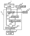
- FIG. 2 is a diagram showing a configuration of the volume data processing unit 8 according to the present embodiment.
- the volume data processing unit 8 includes a gradient calculating unit 801, a feature calculating unit 802, a target voxel determining unit 803, and a voxel removing unit 804.
- the gradient calculation unit 801 calculates the gradient of the voxel value of the volume data generated by the volume data generation unit 7.
- the gradient calculation unit 801 calculates the gradient of the voxel value in each axial direction of the three-dimensional coordinates, and calculates a three-dimensional gradient vector (three-dimensional gradient).
- the feature calculation unit 802 receives the direction of the ultrasonic beam from the beam direction instruction unit 3.
- the feature calculation unit 802 receives the three-dimensional gradient from the gradient calculation unit 801, and calculates the length and direction of the gradient vector based on the gradient in each axial direction of the three-dimensional coordinates.
- the feature calculation unit 802 calculates a normalized gradient vector (gradient normalized vector) having a gradient vector length of 1 for each voxel.
- the feature calculation unit 802 calculates a normalized beam vector (normalized vector of ultrasonic beam) having a beam vector length of the ultrasonic beam of 1 for each voxel.
- the feature calculation unit 802 calculates the inner product of the normalization vector of the ultrasonic beam and the normalization vector of the gradient.
- the feature calculation unit 802 calculates the feature amount of the voxel having the voxel value based on the direction of the ultrasonic beam and the gradient of the voxel value, and calculates the feature space along with the depth of the voxel.
- the target voxel determination unit 803 receives from the feature calculation unit 802 a feature space having at least one of a gradient vector length, a gradient vector direction, and a voxel depth as a feature quantity.
- the target voxel determination unit 803 identifies a target object (for example, a fetal surface) based on the feature space, and determines a voxel corresponding to the target object.
- the target voxel determination unit 803 transmits the determined voxel coordinates to the voxel removal unit 804.
- the voxel removal unit 804 removes voxels with coordinate values shallower than the voxel coordinate value of the target object (voxels located closer to the probe than the target object) from the volume data, and ultrasonically converts the volume data from which the voxel has been removed
- the image is transmitted to the image generation unit 9.
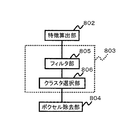
- FIG. 3 is a diagram showing a configuration of the target voxel determination unit 803 according to the present embodiment.
- the target voxel determination unit 803 includes a filter unit 805 and a cluster selection unit 806.
- the target voxel determination unit 803 determines a voxel corresponding to the target object by comparing a preset threshold value with a feature amount using the filter unit 805. For example, the filter unit 805 selects a feature amount larger than the threshold value as the feature amount of the object, and transmits the feature amount to the cluster selection unit 806.
- the cluster selection unit 806 calculates the gradient vector length or the gradient vector direction distribution with respect to the voxel depth based on the feature space.
- the distribution index (variation, etc.) is represented by a variance value.
- the cluster selection unit 806 counts the gradient vector length or the frequency in the gradient vector direction with the depth of the voxel as a class, divides it into a plurality of clusters based on the frequency distribution, and calculates the variance value of each cluster.
- the cluster selection unit 806 determines a voxel corresponding to the object by comparing a preset threshold value with a distribution index. For example, the cluster selection unit 806 selects a cluster having a variance value larger than a predetermined threshold. The cluster selection unit 806 determines a voxel corresponding to the object based on the depth of the voxel. For example, the cluster selection unit 806 determines a voxel having the shallowest average depth of clusters as a voxel corresponding to the target object from among clusters having a variance value larger than a predetermined threshold, and determines the coordinates of the determined voxel. The data is transmitted to the removal unit 804.
- FIG. 4 is a flowchart showing the operation of the ultrasonic diagnostic apparatus according to the present embodiment.
- the present embodiment a case where the fetal surface in the uterus is displayed as an object will be described.
- the operator of the ultrasonic diagnostic apparatus brings the probe 5 into contact with the subject and renders a mid-section image (sagittal image) of the fetus in the uterus by two-dimensional ultrasonic scanning. Then, based on the median cross-sectional image, the direction of the probe 5 for three-dimensional scanning is determined, and the three-dimensional key of the operation unit 2 is pressed (step S101).
- the fact that the 3D key has been pressed is transmitted to the beam direction indicating unit 3, and the beam direction indicating unit 3 indicates the direction of the ultrasonic beam for 3D scanning, the transmitting / receiving unit 4, the volume data generating unit 7. Transmit to the volume data processing unit 8 and the ultrasonic image generation unit 9 (step S102).
- the transmitting / receiving unit 4 receives the direction of the ultrasonic beam and generates a transmission signal of the ultrasonic beam emitted in the direction of the instructed ultrasonic beam. Based on the generated transmission signal, the probe 5 starts three-dimensional scanning of the subject (step S103).
- the probe 5 transmits a reception signal to the volume data generation unit 7 via the transmission / reception unit 4, and the volume data generation unit 7 is instructed using the reception signal (reception echo) of the ultrasonic beam as a voxel value.
- the volume data of the subject is generated by arranging in the ultrasonic beam direction (step S104).
- the volume data processing unit 8 Based on the generated volume data, the volume data processing unit 8 identifies the surface of the fetus, removes the voxel located on the probe side from the surface of the fetus from the volume data, and removes the voxel from the volume data. Data is transmitted to the ultrasonic image generation unit 9 (step S105).
- the ultrasound image generation unit 9 generates an image of the fetal surface projected on the two-dimensional plane based on the volume data from which the voxels located on the probe side from the surface of the fetus are removed. Is transmitted to the display unit 10 (step S106). The display unit 10 displays an image of the fetal surface (step S107).
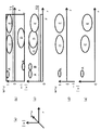
- the volume data generation unit 7 generates volume data represented by a three-dimensional structure.
- the volume data generation unit 7 sets the depth direction of the ultrasonic beam as the r-axis and the scanning direction of the ultrasonic beam as ⁇ .
- Volume data is generated as an axis and a ⁇ axis.
- the volume data generation unit 7 arranges the received signal of the ultrasonic beam as data in the r-axis direction (ultrasonic beam direction) according to the scanning direction ⁇ -axis and ⁇ -axis, and r ⁇ as shown in FIG. A space 70 is formed. Further, as shown in FIG. 5 (b), based on the volume data generated by the volume data generation unit 7, volume data of an arbitrary cross section 71 is extracted from the r ⁇ space 70, as shown in FIG. 5 (c). In addition, a partial region (solid line part) of the cross section 71 of the r ⁇ space 70 is displayed on the display unit 10.
- FIG. 6 is a diagram showing fetal volume data in the uterus. Normally, a three-dimensional image projected on a two-dimensional plane is represented based on volume data, which is three-dimensional data. For convenience of explanation, a mid-sectional image of a fetus in the uterus is represented here.
- the probe surface 60, the fat layer 61, the uterus 62, the amniotic fluid 63, the fetal surface 64, the fetal front high echo area 65, the fetal low echo area 66 and the fetal rear high echo area 67 are generated as volume data by the volume data generation unit 7.
- the area F shown by diagonal lines in FIG. 6 is an area where the reflected echo signal is weak and is displayed dark with low brightness (low echo area), and the area without the diagonal line is displayed with high reflected brightness and high brightness and brightness. Area (high echo area).
- the uterus 62, the fetal high echo area 65, and the fetal high echo area 67 are high echo areas, and the fat layer 61, the amniotic fluid 63, and the fetal low echo area 66 are low echo areas.
- the volume data processing unit 8 identifies the fetal surface 64 that is the boundary between the amniotic fluid 63 and the fetal front high echo area 65, and determines the voxel corresponding to the fetal surface 64 from the volume data.
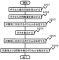
- FIG. 7 is a flowchart showing the operation of the volume data processing unit 8 for identifying the fetal surface 64.
- the gradient calculation unit 801 calculates the gradient of the voxel value of the volume data using an operator (step S201).
- an operator for calculating the gradient a known one such as Prewitt or Sobel may be used.
- a simple operator will be used for explanation.
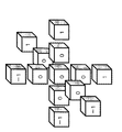
- FIG. 8 (a) is a diagram showing the calculation target range of the operator around a predetermined target voxel in the volume 80.
- FIG. FIG. 8 (b) is a diagram showing operator coefficients to be multiplied to each voxel value.
- the gradient calculating unit 801 calculates the gradient of the target voxel using three voxels in the respective coordinate axis directions (front / rear / left / right / up / down) as a calculation target range.
- the gradient calculating unit 801 multiplies each calculation target voxel value by an operator coefficient and sums it for each coordinate axis, and calculates the total value as the gradient of each coordinate axis. For example, in FIG.
- the gradient calculation unit 801 calculates the gradient of each voxel of the volume data, and the gradient is a vector (three-dimensional gradient) having components in the coordinate axis directions.
- the gradient calculation unit 801 calculates a three-dimensional gradient as a gradient vector.
- the feature calculation unit 802 calculates the length of the gradient vector, the direction of the gradient vector, and the normalization vector of the ultrasonic beam and the normalization vector of the gradient.
- the inner product is calculated as the feature quantity of the voxel (step S202).
- the target voxel determination unit 803 identifies the fetal surface based on the feature amount calculated by the feature calculation unit 802, and determines a voxel corresponding to the fetal surface (step S203).
- the operation of the target voxel determination unit 803 will be described with reference to FIGS.
- FIG. 9 is a diagram showing a gradient vector indicated by an arrow on a fetus midline sectional image. Normally, gradients are calculated for all voxels in the volume, but for convenience of explanation, gradient vectors having a long vector length are mainly illustrated. The length of the arrow represents the gradient vector length, and the direction of the arrow represents the gradient vector direction.
- the long gradient vector includes the boundary A between the fat layer 61 and the uterus 62, the boundary B between the uterus 62 and the amniotic fluid 63, the boundary C between the amniotic fluid 63 and the anterior fetal hyperechoic region 65, and the anterior fetus A boundary D between the high echo area 65 and the fetal low echo area 66 and a boundary E between the fetal low echo area 66 and the fetal rear high echo area 67.
- the vectors of the boundary A and the boundary B are almost the same as the direction of the ultrasonic beam b (that is, the variation is relatively small), but the vector directions are opposite.
- the vector direction of the boundary A is the depth direction.
- the vector direction of the boundary B is opposite to the depth direction.
- the vector directions of the gradient vectors at the boundary C and the boundary E are substantially the same as the direction of the ultrasonic beam b (depth direction), but the directions vary (that is, the variations are relatively large).
- the vector direction of the gradient vector at the boundary D is on the probe side (in the direction opposite to the depth direction), but the direction varies (that is, the variation is relatively large).
- the gradient vector (not shown) in the region F other than the boundaries A to E has a shorter vector length and a greater variation in vector orientation than the gradient vectors of the boundaries A to E.
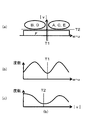
- FIG. 10 is a diagram showing the vector length and vector direction distribution of the gradient vector with respect to the voxel depth.
- FIG. 10 (a) is a three-dimensional feature space representing feature quantities (vector length
- the vector direction is represented by a vector direction with respect to the direction of the ultrasonic beam b, and specifically, is represented by an inner product w ⁇ u of the normalization vector of the ultrasonic beam b and the normalization vector of the gradient.
- w is a unit vector (normalized beam vector) of the ultrasonic beam b.
- u is a normalized gradient vector normalized by dividing the gradient vector v by the gradient vector length
- FIG. 10 (b) is a diagram showing the distribution of the vector direction w ⁇ u of the gradient vector with respect to the voxel depth r.
- FIG. 10 (c) is a diagram showing the distribution of the vector length
- the feature amount is represented by a three-dimensional feature space having a vector length
- the vector direction w ⁇ u and the vector length with respect to the voxel depth r are used. A description will be made separately with
- FIG. 10 (b) is a diagram showing the distribution of the vector direction w ⁇ u of the gradient vector with respect to the voxel depth r.
- FIG. 10 (c) is a diagram showing the distribution of the vector length
- the feature amount is represented
- the vector directions w ⁇ u with respect to the voxel depth r are distributed, and the vector directions w ⁇ u of the boundaries A to E and the region F shown in FIG. 9 are distributed in the distribution regions A to F, respectively.
- the region F shown in FIG. 9 has a large variation in the vector direction w ⁇ u as compared to the boundaries A to E. Therefore, as shown in FIG. 10B, the distribution region F is distributed as a whole.
- with respect to the voxel depth r is distributed, and the vector lengths
- the distribution region F is distributed with a small value as shown in FIG. 10 (c).
- the target voxel determination unit 803 identifies the fetal surface 64 (boundary C) based on the feature amount, and determines the voxels in the distribution region of the boundary C.
- clustering In order to specify the boundary distribution region.
- the volume data of the three-dimensional feature space is clustered using the conventional technique, the clustering process takes a long time.
- the target voxel determination unit 803 compares the preset threshold value and the feature amount, thereby A method of determining a voxel corresponding to an object and a method of determining a voxel corresponding to an object by comparing a preset threshold value with a distribution index (variation) are used.
- the target voxel determination unit 803 determines a voxel corresponding to the target object by using the filter unit 805 to compare a preset threshold value with the feature amount (step S203).
- a preset threshold value As shown in FIG. 10 (b), when the threshold value of the preset vector direction w ⁇ u is T1, the filter unit 805 filters and selects the distribution in the region of the vector direction w ⁇ u larger than the threshold value T1. To do.
- a part of the distribution region F and the distribution regions A, C, and E are selected. Also, as shown in FIG.
- the filter unit 805 if the threshold value of the preset vector length
- the cluster selection unit 806 included in the target voxel determination unit 803 calculates an index (variation) of the distribution of the vector length
- FIG. 11A is a diagram showing the distribution of the distribution areas A, C, and E selected by the filter unit 805.
- FIG. 11 (b) shows the frequency distribution of the distribution regions A, C, and E with the voxel depth as a class. For the frequency distribution, any one of the vector length
- the cluster selection unit 806 distinguishes the frequency distributions of the distribution regions A, C, and E.
- the slope of the curve of the frequency distribution may be calculated by first-order differentiation or the like, and a location where the slope changes from negative to positive may be used as a boundary.
- the slope of the frequency distribution may be obtained by connecting the frequencies for each class with a straight line, and using the slope of the straight line, or using the slope of a curve obtained by performing smoothing processing on the frequency distribution connected with the straight line.
- the cluster selection unit 806 distinguishes the frequency distributions of the distribution regions A, C, and E, thereby dividing the frequency distribution into a plurality of clusters (clusters of the distribution regions A, C, and E). Separately, the variance value is calculated based on the frequency distribution of each cluster. Since the boundary A between the fat layer 61 and the uterus 62 shown in FIG. 9 has a substantially constant depth r in the ultrasonic beam direction compared to the boundaries C and E, the dispersion value of the distribution region A corresponding to the boundary A is other than Compared to the distribution regions C and E of FIG. Therefore, as shown in FIG.
- the cluster selection unit 806 selects clusters (distribution regions C and E) having a variance value larger than the threshold value T3. Further, among the selected clusters, the cluster selection unit 806 determines a cluster (distribution region C) having the shallowest average value of the cluster depth r as a voxel corresponding to the fetal surface 64 (boundary C) (step S205). ). That is, the cluster selection unit 806 selects the distribution region C based on the threshold T3 and the depth r, and removes unnecessary boundaries A and E.
- FIG. 12 is a midline image of the fetus in a state where the boundary C is selected and the voxels at the boundary C (the voxels located on the probe side from the fetal surface) are removed.
- the voxel removal unit 804 removes voxels having coordinate values shallower than the voxel coordinate values of the boundary C corresponding to the selected distribution region C from the volume data (step S206).
- the method for removing the voxel from the volume data may be any method suitable for the operation of the ultrasonic image generation unit 9.
- the ultrasonic image generation unit 9 uses the maximum value projection method, the voxel value of the voxel can be set to 0 to remove the voxel.
- the ultrasonic image generation unit 9 uses an image forming method called ray tracing method or volume ray casting method, it can handle the transparency for each voxel, so by setting the voxel transparency, Voxels can be removed.
- the ultrasonic image generation unit 9 projects the volume data from which the voxels have been removed in two dimensions to form an image of the fetal surface 64, and the display unit 10 displays the formed image of the fetal surface 64.
- the ultrasonic beam is generated by generating the ultrasonic image from the determined voxel based on the direction of the ultrasonic beam and the gradient of the voxel value. Since the gradient of the voxel value is characterized according to the direction of and the feature amount representing the feature of the voxel is calculated, an image of the fetal surface 64 can be drawn with a small amount of calculation.
- the ultrasonic diagnostic apparatus can identify. That is, the ultrasonic diagnostic apparatus according to the present embodiment can appropriately remove the region where the fetal surface 64 (boundary C) and the endometrium (boundary B) are in contact with each other. it can.
- the ultrasonic reflection signal from the area where the fetal surface 64 (boundary C) and the endometrium (boundary B) are in contact is weak because it does not sandwich the amniotic fluid, it is calculated by the gradient calculation unit 801.
- becomes a small value and is included in the distribution region F shown in FIG.
- the ultrasound reflected signal reflected by the fetal skull corresponding to the fetal surface 64 is stronger than the ultrasound reflected signal reflected by the surrounding tissue.
- the voxel value is larger than the voxel value of the surrounding tissue, and the absolute value
- the operation unit 2 can be provided with a variable dial for adjusting the threshold values T1 to T3 or a GUI, so that the identification accuracy of the fetal surface 64 can be adjusted.
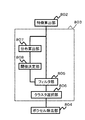
- FIG. 13 is a diagram showing a configuration of the target voxel determination unit 803 according to the present embodiment.
- the target voxel determining unit 803 includes a distribution calculating unit 807 and a threshold determining unit 808.
- the distribution calculation unit 807 calculates the vector length and vector direction distribution of the gradient vector in the feature space based on the feature amount calculated by the feature calculation unit 802.
- the frequency distribution calculation unit 807 calculates a frequency distribution with the vector length
- the threshold determination unit 808 determines thresholds T1 and T2 used in the filter unit 805 based on the vector length and vector direction distribution calculated by the distribution calculation unit 807.
- the threshold determination unit 808 transmits the determined thresholds T1 and T2 to the filter unit 805.
- FIG. 14 (a) is a diagram showing the distribution of the vector length
- FIG. 14B is a diagram showing a frequency distribution of the vector length
- FIG. 14 (c) is a diagram showing a frequency distribution in the vector direction w ⁇ u with the vector length
- the distribution calculation unit 807 calculates the distribution of the vector length
- the threshold value determination unit 808 determines a threshold value T1 for distinguishing between the distribution areas A, C, and E and the distribution areas B and D, and determines the distribution areas A to E and the distribution area F.
- a threshold value T2 to be distinguished is determined.
- the threshold values T1 and T2 for example, there is a binarization process.
- and the vector orientation w ⁇ u in the feature space indicates a bimodal distribution having two peaks, respectively. Values that maximize the ratio of inter-class variance and intra-class variance can be determined as thresholds T1 and T2, respectively.
- the slope of the frequency distribution curve as shown in FIGS. 14 (b) and (c) is calculated by first-order differentiation, etc. May be.
- the determined threshold values T1 and T2 are transmitted to the filter unit 805.
- the filter unit 805 includes the vector length
- the threshold values T1 and T2 can be determined.
- the ultrasonic diagnostic apparatus includes a unit (calculation target range setting unit) for setting a calculation target range of a three-dimensional gradient, and the gradient calculation unit 801 is based on the set calculation target range. Calculate the dimensional gradient.
- FIG. 15 is a diagram showing the volume data processing unit 8 of the present embodiment.
- the gradient calculation unit 801 of the volume data processing unit 8 is connected to the operation unit 2.
- the operation unit 2 changes the calculation target range of the operator used by the gradient calculation unit 801 to calculate the gradient.
- the noise means a structure that is displayed as a part of the fetal surface, such as acoustic noise fringe-like acoustic interference fringes, multiple echoes, and floating substances in amniotic fluid, which are called acoustic noise or speckle. Since the noise is near the fetal surface and the ultrasonic reflection signal is strong, the gradient of the location where the noise exists is mainly included in the distribution region C of the feature space shown in FIGS. 10 (b) and 10 (c). The noise is localized in a region smaller than the fetal surface. Using the property that this noise is localized, the gradient calculation unit 801 calculates the gradient so that the noise is not included in the distribution region C of the feature space shown in FIGS. 10B and 10C.
- the operation target range of the operator is changed by the operation unit 2.
- the gradient is calculated using an operator having a property that the gradient vector length
- FIG. 16 is a diagram showing a calculation target range of the operator adjusted by the operation unit 2.
- the calculation target range of the operator in FIG. 16 is wider than the calculation target range shown in FIG. 8 (b). That is, as compared with FIG. 8 (b), the calculation target range up to two voxels is set as the calculation target for each coordinate axis.
- decreases for localized noise
- on the fetal surface can be reduced, and a large structure such as the fetal surface can be selectively captured. That is, if the noise gradient is calculated with the operator of FIG.
- noise is included in the distribution region C of the feature space shown in FIGS. 10 (b) and 10 (c), but if calculated with the operator of FIG. Since noise is included in the distribution region F of the feature space shown in FIGS. 10B and 10C, the noise is removed by removing the distribution region F.
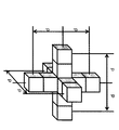
- FIG. 17 is a diagram showing that the calculation target range of the operator is variable.
- d indicates the calculation target range of the operator.
- the calculation target range d is transmitted from the operation unit 2 connected to the gradient calculation unit 801.
- the operator shown in FIG. 8 (b) has d set to 1
- the operator shown in FIG. 16 has d set to 2.
- d By changing d to a value larger than 1, the calculation target range on which the operator operates can be expanded to areas separated by d on the front, rear, left, right, top and bottom of the coordinate axis. In this way, by changing d, large structures such as the fetal surface can be selectively captured, and structures (noise, etc.) that are smaller than the fetal surface can be removed. Noise that impairs the accuracy can be removed.
- , the gradient vector direction w ⁇ u, and the voxel depth r are used as the feature amount.
- the feature amount is a vector length
- the filter unit 805 causes the distribution areas A, C, E, and the distribution area to be distributed. A part of F is selected.
- a threshold T1 determined from the distribution of the vector orientations w ⁇ u in the feature space may be used.
- the cluster selection unit 806 selects the cluster (distribution region C) as a fetus.
- the voxel corresponding to the surface 64 (boundary C) is determined.
- the cluster selected by the cluster selection unit 806 includes a part of the distribution area F in addition to the distribution area C, but calculates the gradient.
- the distribution region F is removed, and the voxel corresponding to the fetal surface 64 (boundary C) is determined based on the feature space of the vector orientation w ⁇ u and the voxel depth r can do. In this case, it is desirable to set the calculation target range d to 2 or more.
- the filter unit 805 causes the distribution regions A, B, C, D, E is selected.
- in the feature space may be used.
- the cluster selection unit 806 has a variance value smaller than the threshold value T3 based on the frequency distribution (frequency distribution of vector length
- Clusters (distribution areas A, B) are removed, and clusters (distribution areas C, D, E) having a variance value greater than threshold T3 are selected.
- the vectors of the boundary A and the boundary B are almost the same as the direction of the ultrasonic beam b, and the variation is relatively small. Therefore, the dispersion values of the clusters in the distribution regions A and B are also relatively small. Therefore, the variance value is smaller than the threshold value T3 and is removed by the cluster selection unit 806.
- the fetal surface 64 (boundary C) can be drawn by drawing the foremost surface in the line-of-sight direction among the distribution regions C, D, and E selected by the cluster selection unit 806.
- a known drawing method can be applied to draw the foremost surface in the line-of-sight direction. For example, a volume ray casting method, a ray tracing method, or the like is applied.
- threshold values T1 and T2 are determined, and the filter unit 805 selects distribution regions A, C, and E based on the threshold values T1 and T2. Then, a region of interest (ROI) is set in the region estimated to be a fetus, and the distribution region A, which is a relatively shallow region, is removed.
- ROI region of interest
- the ROI can be easily set in the region estimated to be a fetus.
- the surface closest to the line of sight can be drawn to draw the fetal surface 64 (boundary C).
- the vector orientation w -By using at least one of u and vector length
- the fetal surface 64 (boundary C) can be depicted.
- , the vector direction w ⁇ u, and the voxel depth r may be used as the feature amount.
- first-order differentiation or binarization processing is used to distinguish the frequency distribution of the distribution region.
- Other techniques for distinguishing the frequency distribution may be used.
- the distribution index is represented by a variance value, but may be represented by a standard deviation or an average deviation.
- the frequency distribution is used.
- other methods for distinguishing the distribution of the feature amount in the feature space may be used.
- the ultrasonic diagnostic apparatus generates the ultrasonic image from the determined voxel based on the direction of the ultrasonic beam and the gradient of the voxel value, thereby characterizing the gradient of the voxel value according to the direction of the ultrasonic beam.
- the feature amount representing the feature of the voxel is calculated and the voxel of the target object is determined based on the feature space of the feature amount, the surface image of the target object can be drawn with a small amount of calculation.
- it is useful as an ultrasonic diagnostic apparatus for drawing an image of the fetal surface.
- 1 ultrasonic diagnostic device 1 ultrasonic diagnostic device, 2 operation unit, 3 beam direction indicating unit, 4 transmission / reception unit, 5 probe, 7 volume data generation unit, 8 volume data processing unit, 9 ultrasonic image generation unit, 10 display unit, 801 gradient Calculation unit, 802 feature calculation unit, 803 target voxel determination unit, 804 voxel removal unit, 805 filter unit, 806 cluster selection unit, 807 distribution calculation unit, 808 threshold determination unit
Landscapes
- Engineering & Computer Science (AREA)
- Health & Medical Sciences (AREA)
- Life Sciences & Earth Sciences (AREA)
- Physics & Mathematics (AREA)
- Public Health (AREA)
- Medical Informatics (AREA)
- Biomedical Technology (AREA)
- General Health & Medical Sciences (AREA)
- Pathology (AREA)
- Surgery (AREA)
- Biophysics (AREA)
- Nuclear Medicine, Radiotherapy & Molecular Imaging (AREA)
- Veterinary Medicine (AREA)
- Radiology & Medical Imaging (AREA)
- Animal Behavior & Ethology (AREA)
- Heart & Thoracic Surgery (AREA)
- Molecular Biology (AREA)
- Remote Sensing (AREA)
- General Physics & Mathematics (AREA)
- Radar, Positioning & Navigation (AREA)
- Computer Vision & Pattern Recognition (AREA)
- Theoretical Computer Science (AREA)
- Acoustics & Sound (AREA)
- Computer Networks & Wireless Communication (AREA)
- Architecture (AREA)
- Computer Graphics (AREA)
- Computer Hardware Design (AREA)
- General Engineering & Computer Science (AREA)
- Software Systems (AREA)
- Gynecology & Obstetrics (AREA)
- Pregnancy & Childbirth (AREA)
- Data Mining & Analysis (AREA)
- Databases & Information Systems (AREA)
- Epidemiology (AREA)
- Primary Health Care (AREA)
- Ultra Sonic Daignosis Equipment (AREA)
Abstract
Description
以下、本発明の第1の実施の形態にかかる超音波診断装置について、図面を用いて説明する。図1は、本実施の形態にかかる超音波診断装置の構成を概念的に示した図である。
超音波診断装置1は、操作部2、ビーム方向指示部3、送受信部4、探触子5、ボリュームデータ生成部7、ボリュームデータ処理部8、超音波画像生成部9、及び表示部10を備える。
図9~図12を用いて、対象ボクセル決定部803の動作を説明する。図9は、胎児正中断面像に勾配ベクトルを矢印で示した図である。通常は、ボリューム内の全てのボクセルについて勾配を算出するが、説明の便宜のため、ベクトル長さが長い勾配ベクトルを主に図示している。矢印の長さは勾配ベクトル長さを表し、矢印の向きは勾配ベクトル向きを表している。
度数分布の傾きは、階級毎の度数を直線で結んで、直線の傾きを用いてもよいし、直線で結ばれた度数分布にスムージング処理を施した曲線の傾きを用いてもよい。
以下、本発明の第2の実施の形態にかかる超音波診断装置について、図面を用いて説明する。特に言及しない場合は、他の構成は、第1の実施の形態にかかる超音波診断装置と同様である。
対象ボクセル決定部803は、分布算出部807及び閾値決定部808を備える。分布算出部807は、特徴算出部802により算出された特徴量に基づいて、特徴空間における勾配ベクトルのベクトル長さ及びベクトル向きの分布を算出する。本実施の形態では、度数分布算出部807は、勾配ベクトルのベクトル長さ|v|を階級とした度数分布とベクトル向きw・uを階級とした度数分布を算出する。閾値決定部808は、分布算出部807により算出されたベクトル長さ及びベクトル向きの分布に基づいて、フィルタ部805で用いられる閾値T1及びT2を決定する。閾値決定部808は、決定された閾値T1及びT2をフィルタ部805へ送信する。
以下、本発明の第3の実施の形態にかかる超音波診断装置について、図面を用いて説明する。特に言及しない場合は、他の構成は、第1及び第2の実施の形態にかかる超音波診断装置と同様である。本実施の形態にかかる超音波診断装置は、3次元の勾配の演算対象範囲を設定する手段(演算対象範囲設定部)を備え、勾配算出部801は、設定された演算対象範囲に基づき、3次元の勾配を算出する。
Claims (15)
- 探触子から超音波ビームを送受信することにより、対象物のボリュームデータを生成するボリュームデータ生成部と、ボリュームデータ生成部に生成された対象物の超音波画像を生成するボリュームデータ処理部と、前記対象物に対応する前記超音波画像を生成する超音波画像生成部を備えた超音波診断装置であって、
前記ボリュームデータ処理部は、
前記ボリュームデータのボクセルの値の勾配を算出する勾配算出部と、
前記勾配及び前記超音波ビームの向きに基づいて前記ボクセルの特徴量を算出し、前記特徴量に基づいて特徴空間を算出する特徴算出部と、
前記特徴空間に基づいて、前記対象物に対応する前記ボクセルを決定する対象ボクセル決定部と、
前記対象物から前記探触子側に位置するボクセルを除去するボクセル除去部とを具備したことを特徴とする超音波診断装置。 - 前記対象ボクセル決定部は、前記特徴空間における前記勾配のベクトル長さ及びベクトル向きの少なくとも1つの分布に基づいて、前記対象物を含む前記ボクセルを決定するクラスタ選択部を備えたことを特徴とする請求項1に記載の超音波診断装置。
- 前記クラスタ選択部の前記ベクトル向きは、前記超音波ビームの正規化ベクトルと前記ボリュームデータのボクセルの値の勾配の正規化ベクトルとの内積で表されることを特徴とする請求項2に記載の超音波診断装置。
- 前記クラスタ選択部の前記分布は、深度を階級とする前記ベクトル長さ又は前記ベクトル向きの度数分布であって、前記分布の指標は、前記度数分布に基づく分散値、標準偏差、及び平均偏差の少なくとも1つで表されることを特徴とする請求項2に記載の超音波診断装置。
- 前記対象ボクセル決定部は、予め設定された閾値と前記特徴量とを比較することにより、前記対象物を含む前記ボクセルを決定することを特徴とする請求項1に記載の超音波診断装置。
- 前記対象ボクセル決定部は、
前記特徴空間における前記勾配のベクトルの長さ及び向きの少なくとも1つの分布を算出する分布算出部と、
前記分布に基づいて前記閾値を決定する閾値決定部と
を備えたことを特徴とする請求項5に記載の超音波診断装置。 - 前記特徴算出部は、前記ボリュームデータのボクセルの値の勾配のベクトルの長さ、向き、及び前記ボクセルの深度の少なくとも1つを前記特徴量とする特徴空間を算出することを特徴とする請求項1に記載の超音波診断装置。
- 前記ボクセル除去部は、前記探触子側に位置するボクセルのボクセル値を所定値とすることを特徴とする請求項1に記載の超音波診断装置。
- 前記ボクセル除去部は、前記探触子側に位置するボクセルの透明度を設定することを特徴とする請求項1に記載の超音波診断装置。
- 前記勾配算出部は、演算子に基づいて3次元の前記勾配を算出し、
前記演算子の演算対象範囲が可変であることを特徴とする請求項1に記載の超音波診断装置。 - 3次元の前記勾配の演算対象範囲を設定する手段を備え、
前記勾配算出部は、前記設定された演算対象範囲に基づき、前記3次元の前記勾配を算出することを特徴とする請求項1に記載の超音波診断装置。 - 探触子を有する超音波診断装置により取得されたボリュームデータから対象物の超音波画像を生成する超音波画像描出方法であって、
前記ボリュームデータのボクセル値の勾配を算出するステップと、
前記勾配のベクトル向き及び前記ボクセル値の前記勾配に基づいて、ボクセルの特徴量を算出し、前記特徴量に基づいて特徴空間を算出するステップと、
前記特徴空間に基づいて、前記対象物に対応する前記ボクセルを決定するステップと、
前記対象物よりも前記探触子側に位置するボクセルを除去するステップと、
前記探触子側に位置するボクセルが除去された前記ボリュームデータから、前記対象物に対応する超音波画像を生成するステップと、を含むことを特徴とする超音波画像描出方法。 - 前記ボクセルを決定するステップは、前記特徴空間における前記勾配のベクトル長さ及びベクトル向きの少なくとも1つの分布に基づいて、前記対象物を含む前記ボクセルを決定するクラスタ選択ステップを備えることを特徴とする請求項12に記載の超音波画像描出方法。
- 前記ボクセルを決定するステップは、予め設定された閾値と前記特徴量とを比較することにより、前記対象物を含む前記ボクセルを決定することを特徴とする請求項12に記載の超音波画像描出方法。
- 前記特徴空間を算出するステップは、前記ボリュームデータのボクセルの値の勾配のベクトルの長さ、向き、及び前記ボクセルの深度の少なくとも1つを前記特徴量とする特徴空間を算出することを特徴とする請求項12に記載の超音波画像描出方法。
Priority Applications (3)
| Application Number | Priority Date | Filing Date | Title |
|---|---|---|---|
| JP2013509833A JPWO2012140984A1 (ja) | 2011-04-14 | 2012-03-15 | 超音波診断装置と超音波画像描出方法 |
| CN2012800180094A CN103458798A (zh) | 2011-04-14 | 2012-03-15 | 超声波诊断装置和超声波图像描绘方法 |
| US14/007,841 US20140018682A1 (en) | 2011-04-14 | 2012-03-15 | Ultrasonic diagnostic apparatus and ultrasonic diagnostic image rendering method |
Applications Claiming Priority (2)
| Application Number | Priority Date | Filing Date | Title |
|---|---|---|---|
| JP2011-090131 | 2011-04-14 | ||
| JP2011090131 | 2011-04-14 |
Publications (1)
| Publication Number | Publication Date |
|---|---|
| WO2012140984A1 true WO2012140984A1 (ja) | 2012-10-18 |
Family
ID=47009166
Family Applications (1)
| Application Number | Title | Priority Date | Filing Date |
|---|---|---|---|
| PCT/JP2012/056618 Ceased WO2012140984A1 (ja) | 2011-04-14 | 2012-03-15 | 超音波診断装置と超音波画像描出方法 |
Country Status (4)
| Country | Link |
|---|---|
| US (1) | US20140018682A1 (ja) |
| JP (1) | JPWO2012140984A1 (ja) |
| CN (1) | CN103458798A (ja) |
| WO (1) | WO2012140984A1 (ja) |
Cited By (5)
| Publication number | Priority date | Publication date | Assignee | Title |
|---|---|---|---|---|
| JP2012239576A (ja) * | 2011-05-18 | 2012-12-10 | Hitachi Aloka Medical Ltd | 超音波診断装置 |
| WO2016056458A1 (ja) * | 2014-10-08 | 2016-04-14 | 日立アロカメディカル株式会社 | 超音波画像処理装置及び超音波画像処理方法 |
| WO2017006595A1 (ja) * | 2015-07-03 | 2017-01-12 | 株式会社日立製作所 | 超音波診断装置及び超音波画像処理方法 |
| WO2018110558A1 (ja) * | 2016-12-12 | 2018-06-21 | キヤノン株式会社 | 画像処理装置、画像処理方法及びプログラム |
| CN111369683A (zh) * | 2020-02-26 | 2020-07-03 | 西安理工大学 | 一种多域物质体数据内部分界面提取方法 |
Families Citing this family (8)
| Publication number | Priority date | Publication date | Assignee | Title |
|---|---|---|---|---|
| CN104260837A (zh) * | 2014-10-17 | 2015-01-07 | 浙江海洋学院 | 一种礁石探寻渔船 |
| US10373062B2 (en) * | 2014-12-12 | 2019-08-06 | Omni Ai, Inc. | Mapper component for a neuro-linguistic behavior recognition system |
| JP5957109B1 (ja) * | 2015-02-20 | 2016-07-27 | 株式会社日立製作所 | 超音波診断装置 |
| EP3106096B1 (en) | 2015-06-12 | 2020-02-19 | Samsung Medison Co., Ltd. | Method and apparatus for displaying ultrasound images |
| JP2020501648A (ja) * | 2016-12-02 | 2020-01-23 | デルフィヌス メディカル テクノロジーズ, インコーポレイテッド | 超音波トモグラフィのための波形強化反射およびマージン境界特徴付け |
| CN107518920B (zh) * | 2017-09-30 | 2020-02-18 | 深圳开立生物医疗科技股份有限公司 | 超声波图像处理方法及装置、超声诊断装置及存储介质 |
| EP3784139A4 (en) | 2018-04-27 | 2021-12-29 | Delphinus Medical Technologies, Inc. | System and method for feature extraction and classification on ultrasound tomography images |
| EP4202843A1 (en) * | 2021-12-22 | 2023-06-28 | MinMaxMedical | Method and device for enhancing the display of features of interest in a 3d image of an anatomical region of a patient |
Citations (3)
| Publication number | Priority date | Publication date | Assignee | Title |
|---|---|---|---|---|
| JP2001145631A (ja) * | 1999-11-22 | 2001-05-29 | Aloka Co Ltd | 超音波診断装置 |
| JP2006288471A (ja) * | 2005-04-06 | 2006-10-26 | Toshiba Corp | 3次元超音波診断装置及びボリュームデータ表示領域設定方法 |
| JP2010221018A (ja) * | 2009-03-24 | 2010-10-07 | Medison Co Ltd | ボリュームデータに表面レンダリングを行う超音波システムおよび方法 |
Family Cites Families (3)
| Publication number | Priority date | Publication date | Assignee | Title |
|---|---|---|---|---|
| US7022073B2 (en) * | 2003-04-02 | 2006-04-04 | Siemens Medical Solutions Usa, Inc. | Border detection for medical imaging |
| CN101292883B (zh) * | 2007-04-23 | 2012-07-04 | 深圳迈瑞生物医疗电子股份有限公司 | 超声三维快速成像方法及其装置 |
| US20090080738A1 (en) * | 2007-05-01 | 2009-03-26 | Dror Zur | Edge detection in ultrasound images |
-
2012
- 2012-03-15 US US14/007,841 patent/US20140018682A1/en not_active Abandoned
- 2012-03-15 WO PCT/JP2012/056618 patent/WO2012140984A1/ja not_active Ceased
- 2012-03-15 CN CN2012800180094A patent/CN103458798A/zh active Pending
- 2012-03-15 JP JP2013509833A patent/JPWO2012140984A1/ja active Pending
Patent Citations (3)
| Publication number | Priority date | Publication date | Assignee | Title |
|---|---|---|---|---|
| JP2001145631A (ja) * | 1999-11-22 | 2001-05-29 | Aloka Co Ltd | 超音波診断装置 |
| JP2006288471A (ja) * | 2005-04-06 | 2006-10-26 | Toshiba Corp | 3次元超音波診断装置及びボリュームデータ表示領域設定方法 |
| JP2010221018A (ja) * | 2009-03-24 | 2010-10-07 | Medison Co Ltd | ボリュームデータに表面レンダリングを行う超音波システムおよび方法 |
Cited By (10)
| Publication number | Priority date | Publication date | Assignee | Title |
|---|---|---|---|---|
| JP2012239576A (ja) * | 2011-05-18 | 2012-12-10 | Hitachi Aloka Medical Ltd | 超音波診断装置 |
| WO2016056458A1 (ja) * | 2014-10-08 | 2016-04-14 | 日立アロカメディカル株式会社 | 超音波画像処理装置及び超音波画像処理方法 |
| JP2016073541A (ja) * | 2014-10-08 | 2016-05-12 | 日立アロカメディカル株式会社 | 超音波画像処理装置、プログラム及び超音波画像処理方法 |
| WO2017006595A1 (ja) * | 2015-07-03 | 2017-01-12 | 株式会社日立製作所 | 超音波診断装置及び超音波画像処理方法 |
| JP2017012587A (ja) * | 2015-07-03 | 2017-01-19 | 株式会社日立製作所 | 超音波診断装置及びプログラム |
| WO2018110558A1 (ja) * | 2016-12-12 | 2018-06-21 | キヤノン株式会社 | 画像処理装置、画像処理方法及びプログラム |
| JPWO2018110558A1 (ja) * | 2016-12-12 | 2019-10-24 | キヤノン株式会社 | 画像処理装置、画像処理方法及びプログラム |
| US10997699B2 (en) | 2016-12-12 | 2021-05-04 | Canon Kabushiki Kaisha | Image processing apparatus and image processing method |
| CN111369683A (zh) * | 2020-02-26 | 2020-07-03 | 西安理工大学 | 一种多域物质体数据内部分界面提取方法 |
| CN111369683B (zh) * | 2020-02-26 | 2023-11-17 | 西安理工大学 | 一种多域物质体数据内部分界面提取方法 |
Also Published As
| Publication number | Publication date |
|---|---|
| JPWO2012140984A1 (ja) | 2014-07-28 |
| US20140018682A1 (en) | 2014-01-16 |
| CN103458798A (zh) | 2013-12-18 |
Similar Documents
| Publication | Publication Date | Title |
|---|---|---|
| WO2012140984A1 (ja) | 超音波診断装置と超音波画像描出方法 | |
| JP4550599B2 (ja) | 3次元超音波映像形成装置及び方法 | |
| CN102596050B (zh) | 超声波成像装置及超声波成像方法 | |
| US9782151B2 (en) | Sensor coordinate calibration in an ultrasound system | |
| CN113260314B (zh) | 用于对比增强成像的系统和方法 | |
| CN105073014B (zh) | 超声波摄像装置以及超声波图像显示方法 | |
| CN110072465B (zh) | 用于肺部超声的目标探头放置 | |
| CN1868407B (zh) | 用于处理超声频谱图像的设备及方法 | |
| KR20170053685A (ko) | 초음파 측정치 및 그래픽 모델을 산출하여 표시함에 의한 태아 영상화 방법 및 시스템 | |
| KR101175426B1 (ko) | 3차원 초음파 영상을 제공하는 초음파 시스템 및 방법 | |
| KR20170068944A (ko) | 초음파 영상을 디스플레이하는 방법 및 이를 위한 초음파 장치 | |
| KR101538658B1 (ko) | 의료 영상 표시 방법 및 장치 | |
| EP1684232A1 (en) | Method of improving the quality of a three-dimensional ultrasound doppler image | |
| US20110213250A1 (en) | 3-d ultrasound imaging with volume data processing | |
| JP5670253B2 (ja) | 超音波診断装置 | |
| JP5271615B2 (ja) | 超音波診断装置 | |
| JP4963278B2 (ja) | 分離測度を用いた重み付け最小二乗法による境界抽出 | |
| EP2157442B1 (en) | Formation of an elastic image in an ultrasound system | |
| CN111383323A (zh) | 一种超声成像方法和系统以及超声图像处理方法和系统 | |
| KR101117913B1 (ko) | 볼륨 데이터를 렌더링하는 초음파 시스템 및 방법 | |
| WO2013069486A1 (en) | Subject information acquisition apparatus, subject information acquisition method, and program | |
| JP4681358B2 (ja) | 超音波診断装置及びボリュームデータ処理方法 | |
| KR101024857B1 (ko) | 3차원 초음파 영상에 컬러 모델링 처리를 수행하는 초음파 시스템 및 방법 | |
| JP6560597B2 (ja) | 超音波画像の処理方法及び超音波画像の処理装置 | |
| KR101341576B1 (ko) | 등고선 기반 관심영역 결정방법 및 장치 |
Legal Events
| Date | Code | Title | Description |
|---|---|---|---|
| 121 | Ep: the epo has been informed by wipo that ep was designated in this application |
Ref document number: 12771939 Country of ref document: EP Kind code of ref document: A1 |
|
| ENP | Entry into the national phase |
Ref document number: 2013509833 Country of ref document: JP Kind code of ref document: A |
|
| WWE | Wipo information: entry into national phase |
Ref document number: 14007841 Country of ref document: US |
|
| NENP | Non-entry into the national phase |
Ref country code: DE |
|
| 122 | Ep: pct application non-entry in european phase |
Ref document number: 12771939 Country of ref document: EP Kind code of ref document: A1 |