WO2012141040A1 - 情報処理装置、記憶媒体、および、情報処理方法 - Google Patents
情報処理装置、記憶媒体、および、情報処理方法 Download PDFInfo
- Publication number
- WO2012141040A1 WO2012141040A1 PCT/JP2012/059046 JP2012059046W WO2012141040A1 WO 2012141040 A1 WO2012141040 A1 WO 2012141040A1 JP 2012059046 W JP2012059046 W JP 2012059046W WO 2012141040 A1 WO2012141040 A1 WO 2012141040A1
- Authority
- WO
- WIPO (PCT)
- Prior art keywords
- input
- acceleration
- information processing
- input unit
- detected
- Prior art date
- Legal status (The legal status is an assumption and is not a legal conclusion. Google has not performed a legal analysis and makes no representation as to the accuracy of the status listed.)
- Ceased
Links
Images



Classifications
-
- G—PHYSICS
- G06—COMPUTING OR CALCULATING; COUNTING
- G06F—ELECTRIC DIGITAL DATA PROCESSING
- G06F3/00—Input arrangements for transferring data to be processed into a form capable of being handled by the computer; Output arrangements for transferring data from processing unit to output unit, e.g. interface arrangements
- G06F3/01—Input arrangements or combined input and output arrangements for interaction between user and computer
- G06F3/048—Interaction techniques based on graphical user interfaces [GUI]
- G06F3/0487—Interaction techniques based on graphical user interfaces [GUI] using specific features provided by the input device, e.g. functions controlled by the rotation of a mouse with dual sensing arrangements, or of the nature of the input device, e.g. tap gestures based on pressure sensed by a digitiser
- G06F3/0488—Interaction techniques based on graphical user interfaces [GUI] using specific features provided by the input device, e.g. functions controlled by the rotation of a mouse with dual sensing arrangements, or of the nature of the input device, e.g. tap gestures based on pressure sensed by a digitiser using a touch-screen or digitiser, e.g. input of commands through traced gestures
- G06F3/04883—Interaction techniques based on graphical user interfaces [GUI] using specific features provided by the input device, e.g. functions controlled by the rotation of a mouse with dual sensing arrangements, or of the nature of the input device, e.g. tap gestures based on pressure sensed by a digitiser using a touch-screen or digitiser, e.g. input of commands through traced gestures for inputting data by handwriting, e.g. gesture or text
Definitions
- the present invention relates to an information processing apparatus, and more particularly to an information processing apparatus that accepts handwritten input.
- the present invention has been conceived in view of such a situation, and an object thereof is to improve convenience for a user in an information processing apparatus.
- An information processing apparatus includes an input unit for receiving handwritten input, a detection unit for detecting acceleration applied to the input unit, and an acceleration detected by the detection unit satisfying a predetermined condition. As a condition, a control unit that corrects an input to the input unit is provided.
- control unit corrects the input to the input unit so that the input to the input unit before and after the detection is connected when the detection unit detects an acceleration of a predetermined magnitude or larger.
- the detection unit detects acceleration in two directions included in a surface on which the input unit accepts handwritten input.
- the detection unit detects an acceleration in a direction where the input unit intersects a surface that accepts handwritten input.
- the storage medium according to the present invention is a computer-readable storage medium in which a computer-executable program provided in an information processing apparatus including an input unit that receives handwritten input is recorded non-temporarily.
- the program causes the computer to execute a step of detecting an acceleration applied to the input unit and a step of correcting an input to the input unit on condition that the detected acceleration satisfies a predetermined condition.
- the information processing method is an information processing method executed in an information processing apparatus including an input unit that accepts handwritten input.
- the information processing method includes a step of detecting an acceleration applied to the input unit, and a step of correcting an input to the input unit on condition that the detected acceleration satisfies a predetermined condition.
- the input to the input unit is corrected on condition that the acceleration detected by the detection unit satisfies a predetermined condition.
- FIG. 1 is an image diagram showing an appearance of a portable terminal 100 which is an embodiment of an information processing apparatus of the present invention.
- the portable terminal 100 includes a touch panel 103 that accepts handwritten input, notification units 112A to 112C that perform various notifications, and buttons 115A to 115E that input information by operation.
- the user inputs information such as graphic information to the touch panel 103 by using the stylus pen 120 or the like for the mobile terminal 100.
- FIG. 1 schematically shows an X axis, a Y axis, and a Z axis for the mobile terminal 100. These three axes are orthogonal to each other.
- the touch panel 103 is provided in a planar shape.
- the X axis and the Y axis are axes along the plane.
- the Z axis is an axis perpendicular to the plane.
- the mobile terminal 100 is provided with sensors (acceleration sensors 106X to 106Z described later) for detecting acceleration applied to each of the X-axis direction, the Y-axis direction, and the Z-axis direction.
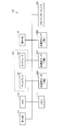
- FIG. 2 is a block diagram illustrating a hardware configuration of the mobile terminal 100 of FIG.
- the mobile terminal 100 includes a display 101, a touch sensor 102, an operation unit 115, a memory interface 109, a CPU (Central Processing Unit) 110, a memory 111, and a display unit 112.
- a display 101 includes a touch sensor 102, an operation unit 115, a memory interface 109, a CPU (Central Processing Unit) 110, a memory 111, and a display unit 112.
- CPU Central Processing Unit
- the display 101 is composed of a liquid crystal display device, for example.
- the touch sensor 102 is attached to the display 101.
- the touch sensor 102 includes, for example, a sheet-like capacitive touch sensor or a resistive film touch sensor.
- the touch panel 103 is configured by the display 101 and the touch sensor 102.
- Display unit 112 includes notification units 112A to 112C.
- the notification units 112A to 112C are each composed of, for example, an LED (Light Emitting Diode).
- CPU 110 can perform various notification operations by lighting / flashing any of notification units 112A to 112C.
- the mobile terminal 100 includes acceleration sensors 106X, 106Y, and 106Z.
- the acceleration sensor 106X is a sensor that detects acceleration in the X-axis direction in FIG.
- the acceleration sensors 106Y and 106Z are sensors that detect accelerations in the Y-axis direction and the Z-axis direction in FIG. 1, respectively.
- the acceleration sensors 106X, 106Y, and 106Z are realized by, for example, a MEMS (Micro Electro Mechanical System) type acceleration sensor including a detection element unit that detects acceleration and a signal processing circuit that amplifies and adjusts the signal from the detection element and outputs the signal.
- MEMS Micro Electro Mechanical System
- the present invention is not limited to this, and any method may be adopted as long as the sensor can detect acceleration.
- the display 101 displays various information by being controlled by the CPU 110.
- the touch sensor 102 detects a touch operation with a user's finger or stylus pen, and inputs the coordinates where the touch operation is performed to the CPU 110.
- the touch sensor 102 detects a contact area with the touch sensor 102 when a touch operation is performed, and inputs the contact area to the CPU 110. Further, the touch sensor 102 detects the pressure when the touch sensor 102 is pressed, and inputs the pressure to the CPU 110.
- the memory interface 109 reads data from a storage medium that can be attached to and detached from the main body of the mobile terminal 100 (for example, a housing that houses the touch panel 103), and inputs the data to the CPU 110 or receives data from the CPU 110. Or stored in the storage medium.
- a storage medium that can be attached to and detached from the main body of the mobile terminal 100 (for example, a housing that houses the touch panel 103), and inputs the data to the CPU 110 or receives data from the CPU 110. Or stored in the storage medium.
- Storage media include CD-ROM (Compact Disc-Read Only Memory), DVD-ROM (Digital Versatile Disk-Read Only Memory), USB (Universal Serial Bus) memory, memory card, FD (Flexible Disk), hard disk, magnetic Tape, cassette tape, MO (Magnetic Optical Disc), MD (Mini Disc), IC (Integrated Circuit) card (excluding memory card), optical card, mask ROM, EPROM, EEPROM (Electronically Erasable Programmable Read-Only Memory), etc. And a medium for storing the program in a nonvolatile manner.
- the memory 111 is realized by various RAMs, ROMs (Read-Only Memory), hard disks, and the like.
- the memory 111 is a USB memory, CD-ROM, DVD-ROM, memory card, FD, hard disk, magnetic tape, cassette tape, MO, MD, IC card (memory card) used via a reading interface.
- a non-volatile storage medium such as an optical card, mask ROM, EPROM, and EEPROM.
- the memory 111 stores a control program executed by the CPU 110, content data displayed on the touch panel 103, and the like.
- the CPU 110 executes various programs stored in memory 111.
- the processing in the mobile terminal 100 (for example, the processing shown in the flowchart of FIG. 5 or FIG. 6) is realized by each hardware and software executed by the CPU 110.
- Such software may be stored in advance in the memory 111, or may be stored in a storage medium and distributed as a program product.
- the mobile terminal 100 may have a communication function, and the software may be provided as a program product that can be downloaded by an information provider connected to a network.
- Such software is read from the storage medium by using a reading device (not shown), or downloaded by using the communication function and temporarily stored in the memory 111.
- the CPU 110 stores the software in the form of an executable program in the memory 111 and then executes the program.
- the program here includes not only a program that can be directly executed by a processor such as the CPU 110 but also a program in a source program format, a compressed program, and an encrypted program.
- the acceleration sensors 106X to 106Z may be housed inside the casing of the mobile terminal 100 or attached to the outside of the mobile terminal 100 in order to detect acceleration applied to the mobile terminal 100. .
- portable terminal 100 it is determined whether blurring has occurred based on the acceleration detected by acceleration sensors 106X to 106Z.
- Shake means that a force is applied to the main body (touch panel 103) of the mobile terminal 100 to cause the main body to shake.
- the input content to the touch panel 103 is corrected.
- the correction on the XY plane and the blur in the Z-axis direction are independently corrected. The contents of each correction will be described below.
- the XY plane and the Z-axis direction mean the X-axis, the Y-axis, and the Z-axis described with reference to FIG.
- the shake on the XY plane of the mobile terminal 100 is detected based on the acceleration detected by the acceleration sensor 106X and the acceleration detected by the acceleration sensor 106Y. Specifically, for example, when the sum of the square of the acceleration detected by the acceleration sensor 106X and the square of the acceleration detected by the acceleration sensor 106Y exceeds a predetermined value, it is determined that blurring has occurred on the XY plane. In addition, the mere sum which these sensors detect may be sufficient.
- the XY plane corresponds to a surface on touch panel 103 on which touch sensor 102 receives input.
- FIG. 3 is a diagram for explaining correction when the touch panel 103 is applied with a force in the Y-axis direction.
- FIG. 3B shows an example of acceleration detected by the acceleration sensor 106Y in this case.
- an upward acceleration first appears and decreases after showing a peak, and then a downward acceleration appears and decreases after showing a peak. is doing.
- the upward acceleration in FIG. 3B corresponds to the force in the direction of the arrow R1.
- the downward acceleration in FIG. 3B corresponds to the force in the direction opposite to the arrow R1.
- the stylus pen 120 that is in contact with the touch panel 103 moves relative to the touch panel 103. That is, stylus pen 120 moves in the opposite direction to arrow R1 with respect to touch panel 103 when touch panel 103 moves in the direction of arrow R1. Thereafter, when the touch panel 103 moves in the direction opposite to the arrow R ⁇ b> 1, the stylus pen 120 moves in the direction of the arrow R ⁇ b> 1 with respect to the touch panel 103.
- the locus is As shown in FIG. 3A, the locus of the stylus pen 120 during the period in which the stylus pen 120 moves relative to the touch panel 103 as described above due to the shake of the touch panel 103 is shown as “false input data”. In the portion indicated by the erroneous input data, the line extends in the direction opposite to the arrow R1, and then extends in the direction of the arrow R1.
- the CPU 110 detects the occurrence of blurring in the X direction or the Y direction by monitoring the detection outputs of the acceleration sensor 106X and the acceleration sensor 106Y as described above. And when blurring arises, the input with respect to the touch panel 103 in the period is canceled. Then, the input to the touch panel 103 during the canceled period is replaced with an input value that connects the points input to the touch panel 103 before and after the canceled period.
- FIG. 3C the line shown in the touch panel 103 in FIG. 3A is partially corrected and shown in the touch panel 103.
- a point immediately before the canceled period is indicated by a point P1
- a point immediately after is indicated by a point P2.
- the points P1 and P2 are connected by interpolating the data between them.
- any known method can be adopted as such an interpolation method. They may be connected with a straight line, or a technique such as Lagrange interpolation or spline interpolation may be used.
- the shaking of the mobile terminal 100 (touch panel 103) in the Z-axis direction is detected based on the acceleration detected by the acceleration sensor 106Z. Specifically, for example, when the acceleration detected by the acceleration sensor 106Z exceeds a predetermined value, it is determined that blurring has occurred in the Z-axis direction.
- the Z-axis direction corresponds to the direction that intersects the surface of the touch panel 103 that accepts handwritten input.
- FIG. 4 is a diagram for explaining correction when the touch panel 103 is applied with a force in the Z-axis direction.
- FIG. 4A is a diagram illustrating a state in which the stylus pen 120 is in contact with the surface of the mobile terminal 100 on which the touch panel 103 is provided, from the side.
- the Z-axis direction in FIG. 1 is shown in the vertical direction.
- FIG. 4 (C) An example of the detection output of the acceleration sensor 106Z at this time is schematically shown in FIG. In FIG. 4 (C), the downward acceleration is first detected, the magnitude takes a peak and then reduced, and then the upward acceleration is detected and the magnitude takes a peak and then decreases. Yes.
- the downward acceleration in FIG. 4C corresponds to the force in the direction of the arrow RZ
- the upward acceleration in FIG. 4C corresponds to the force in the direction opposite to the arrow RZ.
- the portable terminal 100 After the stylus pen 120 and the touch panel 103 are in contact with each other as shown in FIG. 4 (A) and temporarily separated as shown in FIG. 4 (B), again, When contact is made as shown in FIG. 4A, information input by touching the touch panel 103 is as shown in FIG. 4D. That is, even when the user is trying to input a single line extending from left to right, the stylus pen 120 is temporarily removed from the touch panel 103 and the input is performed as shown in FIG. The line is broken.
- the line input to the touch panel 103 is corrected based on the acceleration in the Z-axis direction as shown in FIG.
- An example of input information after correction for the line shown in FIG. 4D is shown in FIG.
- a single line is displayed in the touch panel 103.
- a point P3 and a point P4 on the line indicate discontinuous portions in FIG.
- the portable terminal 100 basically, when the stylus pen 120 that is in contact with the touch panel 103 is separated from the touch panel 103, it is determined that the pen is up. Therefore, the subsequent contact of the stylus pen 120 with the touch panel 103 is handled as the start of input of a new line.
- the acceleration detected by the acceleration sensor 106Z exceeds a predetermined value, even if the stylus pen 120 moves away from the touch panel 103 during the period.
- the input to the touch panel 103 is corrected so as to connect the interrupted portions of the input lines.
- the points P3 and P4 are connected by interpolating the data between them. Any known method can be employed as the interpolation method. They may be connected with a straight line, or a technique such as Lagrange interpolation or spline interpolation may be used.
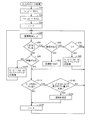
- FIG. 5 is a flowchart of a process (input stroke process) for correcting an input to the touch panel 103 based on the acceleration detected by the acceleration sensors 106X to 106Z in the present embodiment.
- the input stroke process is realized by the CPU 110 executing a program stored in the memory 111, for example.
- the process is started on the condition that, for example, an application that accepts handwritten input is started in the mobile terminal 100.
- CPU 110 first initializes the value (x, y), which is the coordinates of the latest input position, in step S10, and advances the process to step S20.
- x indicates a position in the X-axis direction on the touch panel 103 (touch sensor 102)
- y indicates a position in the Y-axis direction.
- step S20 the CPU 110 initializes the value of (px, py) which is the coordinate of the latest previous input position, and advances the process to step S30.
- px indicates the position in the X-axis direction on the touch panel 103 (touch sensor 102)
- py indicates the position in the Y-axis direction.
- step S30 the CPU 110 resets the value of the counter t to 0, and proceeds to step S40.
- the counter t is a timer that counts the time during which the touch sensor 102 does not detect a touch.
- the count of the counter t is mainly executed by another process executed in parallel with the input stroke process shown in FIG. In the other processing, the CPU 110 continues to count up the counter t during a period in which the touch sensor 102 does not detect a touch.
- the count value of the counter t is reset.
- the counter t starts counting up, and when the state in which no touch is detected is continued, the counter t is continuously counted up.
- step S40 CPU 110 obtains coordinates (x, y) at which a touch is detected by touch sensor 102, and advances the process to step S50.
- the coordinates previously stored as coordinates (x, y) are transferred to coordinates (px, py). If the coordinates can be acquired in step S40, the coordinates (x, y) are updated to the acquired ones. On the other hand, if the coordinate cannot be acquired in step S40 because the touch sensor 102 is not touched, the coordinate (x, y) is set to NULL.
- the content is transferred from the coordinate (x, y) to the coordinate (px, py), so the coordinate (px, py) Becomes NULL.
- the values of the coordinates (x, y) and the coordinates (px, py) are stored in, for example, the memory 111 and updated as appropriate.
- step S50 CPU 110 determines whether or not there is a blur in the Z-axis direction, and proceeds to step S60 where it is determined that there is a blur, and if not, proceeds to step S90.
- whether or not there is a blur in the Z-axis direction is determined based on the acceleration value detected by the acceleration sensor 106 ⁇ / b> Z. Specifically, for example, when the detected acceleration exceeds a predetermined value, it is determined that there is a shake in the Z-axis direction.
- the detection of “there was a shake in the Z-axis direction” in step S50 is, for example, a flag that is set on the condition that the acceleration value detected by the acceleration sensor 106Z exceeds the predetermined value, It may be determined based on whether or not it is set.
- coordinate connection is executed in step S62 as will be described later. The flag is reset on condition that the coordinate connection in step S62 has been executed.
- step S90 the CPU 110 determines whether or not the latest coordinate (x, y) exists. If it is determined that the coordinate is present, the process proceeds to step S110. If it is determined that the latest coordinate (x, y) is not present, the process proceeds to step S100. Specifically, CPU 110 determines that the latest coordinates (x, y) exist when the coordinates can be acquired in step S40 executed immediately before. On the other hand, the CPU 110 determines that the latest coordinates (x, y) do not exist when the coordinates cannot be acquired, such as when the touch sensor 102 is not touched.
- step S100 the CPU 110 puts the value of the same coordinate as the coordinate (px, py) into the coordinate (x, y), and then performs a process when there is a pen-up, and returns the process to step S40.
- the content of the processing when there is a pen-up can apply a known processing content. For example, when the processing is executed, touches detected thereafter on the touch sensor 102 are detected so far. It is treated as an input for a new line that is different from the previous line.
- step S60 the CPU 110 determines whether or not the latest coordinates (x, y) exist as in step S90. If it is determined that it exists, the process proceeds to step S62. If it is determined that it does not exist, the process proceeds to step S70.
- step S70 the CPU 110 determines whether or not the count value of the counter t exceeds a predetermined value T. If it is determined that it has exceeded, the process proceeds to step S80, and if it is determined that it does not exceed, the process returns to step S40.
- step S80 as in step S100, the CPU 110 puts the same coordinate value as the coordinate (px, py) into the coordinate (x, y), and then performs processing when there is a pen-up. Return processing to.
- step S62 as described with reference to FIGS. 4D and 4E, the CPU 110 interpolates the coordinates of the touch position so as to connect the interrupted coordinates, and the process proceeds to step S110. Proceed. Note that as described above, when the flag relating to the blur in the Z-axis direction is set, the CPU 110 resets the flag in step S62.
- step S50 the case where the coordinate of the touch position in the touch sensor 102 cannot be acquired differs depending on whether or not there is a shake in the Z-axis direction.
- step S50 when there is no blur (when NO is determined in step S50), the pen-up process is executed in step S100 only on the condition that the coordinates of the touch position cannot be acquired.
- the pen-up process is executed on the condition that the duration of the state where the coordinates cannot be acquired exceeds T (when YES is determined in step S70). (Step S80). That is, if coordinates are acquired again before the duration exceeds T (if NO is determined in step S70 and YES is determined in step S60), the coordinates may not be acquired temporarily.
- the pen-up process is not executed, and the coordinates of the touch position are interpolated in step S62.
- step S ⁇ b> 110 the CPU 110 determines whether or not blurring has occurred in the XY plane on the touch panel 103 (touch sensor 102). Then, if it is determined that it has occurred, the process proceeds to step S120, and if it is determined that it has not occurred, the process proceeds to step S130.
- the determination as to whether or not blurring has occurred on the XY plane is made, for example, based on whether or not the sum of the square of the acceleration detected by the acceleration sensor 106X and the square of the acceleration detected by the acceleration sensor 106Y exceeds a predetermined value. . If the sum exceeds a predetermined value, it is determined that blur has occurred on the XY plane, and if not, it is determined that blur has not occurred on the XY plane.
- step S120 the CPU 110 determines whether or not the difference between the coordinates (x, y) and the coordinates (px, py) is larger than the difference based on the movement based only on the acceleration detected in step S110. If determined, the process proceeds to step S122. On the other hand, if determined to be small, CPU 110 returns the process to step S40 as it is.
- step S120 for example, the length of the vector from the coordinate (px, py) to the coordinate (x, y) is the length of the acceleration vector in the X-axis direction and the vector in the Y-axis direction detected in step S110. This is realized by determining whether or not it is longer than the length of the sum vector. If the former is longer than the latter (or both are the same), the process proceeds to step S122. On the other hand, if the former is shorter than the latter, the process returns to step S40.
- step S122 as described with reference to FIGS. 3A and 3C, CPU 110 performs touch sensor during a period in which blur is detected based on acceleration detected by acceleration sensor 106X and acceleration sensor 106Y.
- the input coordinates for 102 are corrected, and the process proceeds to step S130.
- the period in which the blur is detected based on the acceleration detected by the acceleration sensor 106X and the acceleration sensor 106Y is, for example, a period in which the sum of the squares of the accelerations detected by these sensors exceeds a predetermined value.
- the input coordinates are corrected, for example, by replacing the coordinate data for the above period with newly created coordinate data.
- the newly created coordinate data includes, for example, data for interpolating coordinates between the coordinate data immediately before these periods and the coordinate data immediately after the periods. Any known method can be employed for the interpolation. They may be connected with a straight line, or a technique such as Lagrange interpolation or spline interpolation may be used.
- step S130 the CPU 110 resets the count value of the counter t to 0, and returns the process to step S40.
- the reset of the counter t in step S130 is executed as an interrupt process for another process for counting the counter t as described above, for example.
- the coordinate data of the touch position in the touch sensor 102 detected during the period in which the shake is detected is obtained.
- the coordinate data for the period is coordinate data (for example, the point P1 of FIG. 3C) connecting the coordinates before and after the period (for example, the point P1 and the point P2 of FIG. 3C).
- a series of coordinate data connecting the points P2 is generated.
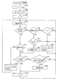
- FIG. 6 is a flowchart of a process of a modification of the input stroke process of FIG.
- step S61 is added to the flowchart of FIG.
- step S60 when it is determined in step S60 that the latest coordinates (x, y) exist, the CPU 110 advances the process to step S61.
- step S61 the CPU 110 determines whether or not the coordinates (px, py) are NULL. If NULL, the process returns to step S40, and if not NULL, the process proceeds to step S62.
- step S62 as described with reference to FIGS. 4D and 4E, the CPU 110 interpolates the coordinates of the touch position so as to connect the interrupted coordinates, and advances the process to step S110.
- step S50 when a blur occurs in the Z-axis direction (when YES is determined in step S50), a touch is detected by the touch sensor 102 at that time (when YES is determined in step S60), and coordinates ( If no coordinates can be acquired as (px, py) (when YES is determined in step S61), the process returns to step S40 without executing the pen-up process, and the next touch to the touch sensor 102 is performed. Wait for operation.
- the input information can be processed by ignoring the coordinates detected when the user accidentally touches the touch sensor 102.
- the touch sensor 102 constitutes an input unit for receiving handwritten input.
- the acceleration sensors 106X, 106Y, and 106Z constitute a detection unit that detects acceleration applied to the input unit.
- the CPU 110 detects that the acceleration detected by the acceleration sensors 106X, 106Y, and 106Z exceeds the predetermined value of the sum of the squares of the accelerations detected by the acceleration sensor 106X and the acceleration sensor 106Y.
- the threshold referred to as “predetermined value” may be set in advance or may be changed as appropriate by the user of the mobile terminal 100.
- the threshold value may be different depending on the mode executed in the mobile terminal 100. For example, when an application for handwriting input is executed on the mobile terminal 100 while using a transportation means such as a train or a bus, shaking is more likely to occur than when the application is executed in a home room. Therefore, the mode executed while using the transportation means is input to the touch sensor 102 on the condition that a larger blur (acceleration) has occurred in the touch sensor 102 than the mode executed in other states.
- the threshold is preferably changed so that the data is corrected.
- an aspect in which the input coordinates in the period when the blur occurs is changed to a series of coordinates that connect the coordinates before and after the blur is exemplified.
- an aspect in which broken lines are connected is exemplified.
- the handwriting input with respect to the portable terminal 100 is not limited to such an aspect.
- the mobile terminal 100 is fixed to a vehicle or the like instead of being held by a user's hand, and even in a situation where acceleration is applied to the touch sensor 102 of the mobile terminal 100 due to vibration in the vehicle, the present invention. Is considered applicable.
- 100 mobile terminal 101 display, 102 touch sensor, 103 touch panel, 106X, 106Y, 106Z acceleration sensor, 110 CPU, 120 stylus pen.
Landscapes
- Engineering & Computer Science (AREA)
- General Engineering & Computer Science (AREA)
- Theoretical Computer Science (AREA)
- Human Computer Interaction (AREA)
- Physics & Mathematics (AREA)
- General Physics & Mathematics (AREA)
- Position Input By Displaying (AREA)
- User Interface Of Digital Computer (AREA)
Abstract
情報処理装置(100)は、手書き入力を受付けるための入力部(102)と、入力部(102)に加えられた加速度を検出するための検出部(106X,106Y,106Z)と、検出部(106X,106Y,106Z)が検出した加速度が所定の条件を満たすことを条件として、入力部(102)に対する入力を補正する制御部(110)とを備える。
Description
本発明は、情報処理装置に関し、特に、手書き入力を受付ける情報処理装置に関する。
近年、情報処理装置において、タッチペンを備え、手書き入力を受け付けるものが多く流通している。このような装置における、入力精度を向上させるための技術が種々提案されている。なお、本願出願人は、本願出願時において、本願発明の先行技術として提出すべき従来技術文献の情報を有していない。
しかしながら、従来の技術では、手ブレが生じるたびに補正が行なわれ、処理が煩雑となったり、意図しない補正が入ったりするおそれがあった。このような煩雑な処理は、情報処理装置における処理全体に遅延を生じ、却って利便性を低下させるおそれがある。
本発明は、かかる実情に鑑み考え出されたものであり、その目的は、情報処理装置において利用者における利便性の向上を図ることである。
本発明に従った情報処理装置は、手書き入力を受付けるための入力部と、入力部に加えられた加速度を検出するための検出部と、検出部が検出した加速度が所定の条件を満たすことを条件として、入力部に対する入力を補正する制御部とを備える。
好ましくは、制御部は、検出部が所定以上の大きさの加速度を検出した場合に、当該検出の前後の入力部に対する入力を連結させるように、入力部に対する入力を補正する。
好ましくは、検出部は、入力部が手書き入力を受付ける面に含まれる2つの方向についての加速度を検出する。
好ましくは、検出部は、入力部が手書き入力を受付ける面に交わる方向についての加速度を検出する。
本発明に従った記憶媒体は、手書き入力を受付ける入力部を含む情報処理装置が備えるコンピュータが実行可能なプログラムを非一時的に記録したコンピュータ読取可能な記憶媒体である。プログラムは、コンピュータに、入力部に加えられた加速度を検出するステップと、検出した加速度が所定の条件を満たすことを条件として、入力部に対する入力を補正するステップとを実行させる。
本発明に従った情報処理方法は、手書き入力を受付ける入力部を含む情報処理装置において実行される情報処理方法である。情報処理方法は、入力部に加えられた加速度を検出するステップと、検出した加速度が所定の条件を満たすことを条件として、入力部に対する入力を補正するステップとを備える。
上記構成によれば、検出部が検出した加速度が所定の条件を満たすことを条件として、入力部に対する入力が補正される。
これにより、手ブレが生じた場合であっても、補正が必要な場合にのみ、補正を行なうことができ、情報処理装置において、処理全体に不要な遅延を生じることなく、利便性を向上できる。
以下、図面を参照しつつ、本発明の実施の形態について説明する。以下の説明では同一の部品は同一の符号が付してある。それらの名称および機能も同じである。したがって、それらについての詳細な説明は繰返さない。
[情報処理装置の概略構成]
図1は、本発明の情報処理装置の一実施の形態である携帯端末100の外観を示すイメージ図である。
図1は、本発明の情報処理装置の一実施の形態である携帯端末100の外観を示すイメージ図である。
携帯端末100は、手書き入力を受付けるタッチパネル103と、各種の通知を行なう通知部112A~112Cと、操作することにより情報を入力するボタン115A~115Eを含む。本実施の形態では、ユーザは、携帯端末100に対して、スタイラスペン120などを用いることによって、タッチパネル103に対して、図形情報等の情報を入力する。
図1では、携帯端末100についてのX軸、Y軸およびZ軸が模式的に示されている。これら3軸は、互いに直行している。本実施の形態では、タッチパネル103が平面状に設けられている。X軸とY軸は、当該平面に沿う軸である。Z軸は、当該平面に垂直な軸である。携帯端末100では、当該携帯端末100に、X軸方向、Y軸方向およびZ軸方向のそれぞれに加えられる加速度を検出するためのセンサ(後述する加速度センサ106X~106Z)が設けられている。
図2は、図1の携帯端末100のハードウェア構成を示すブロック図である。
携帯端末100は、ディスプレイ101と、タッチセンサ102と、操作部115と、メモリインターフェイス109と、CPU(Central Processing Unit)110と、メモリ111と、表示部112とを含む。
携帯端末100は、ディスプレイ101と、タッチセンサ102と、操作部115と、メモリインターフェイス109と、CPU(Central Processing Unit)110と、メモリ111と、表示部112とを含む。
ディスプレイ101は、たとえば液晶表示装置からなる。タッチセンサ102は、ディスプレイ101に貼付されて設けられている。タッチセンサ102は、たとえばシート状の静電容量式タッチセンサや抵抗膜式タッチセンサからなる。携帯端末100では、ディスプレイ101とタッチセンサ102により、タッチパネル103が構成されている。
表示部112は、通知部112A~112Cを含む。通知部112A~112Cは、たとえばそれぞれLED(Light Emitting Diode)からなる。CPU110は、通知部112A~112Cのいずれかを点灯/点滅させることにより、種々の報知動作を行なうことができる。
携帯端末100は、加速度センサ106X,106Y,106Zを含む。加速度センサ106Xは、携帯端末100に加えられた、図1のX軸方向の加速度を検出するセンサである。また、加速度センサ106Y,106Zは、それぞれ、図1のY軸方向,Z軸方向の加速度を検出するセンサである。
加速度センサ106X,106Y,106Zは、たとえば、加速度を検出する検出素子部と検出素子からの信号を増幅・調整して出力する信号処理回路とを含むMEMS(Micro Electro Mechanical System)型加速度センサによって実現されるが、これに限定されず、加速度を検出できるセンサであれば、いかなる方式が採用されても良い。
ディスプレイ101は、CPU110によって制御されることにより、種々の情報を表示する。タッチセンサ102は、ユーザの指やスタイラスペンによるタッチ操作を検出して、当該タッチ操作が行なわれた座標をCPU110に入力する。また、タッチセンサ102は、タッチ操作がなされたときのタッチセンサ102に対する接触面積を検出し、当該接触面積をCPU110に入力する。また、タッチセンサ102は、押下された際の圧力を検出し、当該圧力をCPU110に入力する。
メモリインターフェイス109は、携帯端末100の本体(たとえば、タッチパネル103を収容する筐体)に対して着脱可能な記憶媒体からデータを読出すことによってCPU110に当該データを入力したり、CPU110からのデータを当該記憶媒体に格納したりする。記憶媒体としては、CD-ROM(Compact Disc - Read Only Memory)、DVD-ROM(Digital Versatile Disk - Read Only Memory)、USB(Universal Serial Bus)メモリ、メモリカード、FD(Flexible Disk)、ハードディスク、磁気テープ、カセットテープ、MO(Magnetic Optical Disc)、MD(Mini Disc)、IC(Integrated Circuit)カード(メモリカードを除く)、光カード、マスクROM、EPROM、EEPROM(Electronically Erasable Programmable Read-Only Memory)などの、不揮発的にプログラムを格納する媒体が挙げられる。
また、メモリ111は、各種のRAMや、ROM(Read-Only Memory)や、ハードディスクなどによって実現される。たとえば、メモリ111は、読取用のインターフェイスを介して利用される、USBメモリ、CD-ROM、DVD-ROM、メモリカード、FD、ハードディスク、磁気テープ、カセットテープ、MO、MD、ICカード(メモリカードを除く)、光カード、マスクROM、EPROM、EEPROMなどの、不揮発的にデータを格納する媒体などによっても実現される。なお、メモリ111は、CPU110によって実行される制御プログラムや、タッチパネル103において表示されるコンテンツのデータなどを記憶する。
CPU110は、メモリ111に記憶されている各種のプログラムを実行する。携帯端末100における処理(たとえば、図5または図6のフローチャートで示される処理)は、各ハードウェアおよびCPU110により実行されるソフトウェアによって実現される。このようなソフトウェアは、メモリ111に予め記憶されている場合もあれば、記憶媒体に格納されてプログラム製品として流通している場合もある。あるいは、携帯端末100は通信機能を有し、当該ソフトウェアが、ネットワークに接続されている情報提供事業者によってダウンロード可能なプログラム製品として提供される場合もある。このようなソフトウェアは、図示しない読取装置を利用することによって当該記憶媒体から読取られて、あるいは、上記通信機能を利用することによってダウンロードされて、メモリ111に一旦格納される。CPU110は、ソフトウェアを実行可能なプログラムの形式でメモリ111に格納してから、当該プログラムを実行する。ここでいうプログラムとは、CPU110のようなプロセッサにより直接実行可能なプログラムだけでなく、ソースプログラム形式のプログラム、圧縮処理されたプログラム、暗号化されたプログラムを含む。
加速度センサ106X~106Zは、携帯端末100に加えられた加速度を検出するために、携帯端末100の筐体の内部に収容されていてもよいし、携帯端末100の外部に取付けられていてもよい。
[情報処理装置の機能]
携帯端末100では、加速度センサ106X~106Zによって検出される加速度に基づいて、ブレが生じているか否かが判断される。ブレとは、携帯端末100の本体(タッチパネル103)に対して力が加えられることにより当該本体に揺れが生じることを意味する。そして、ブレが生じていると判断されると、タッチパネル103に対する入力内容が補正される。携帯端末100では、XY平面でのブレとZ軸方向のブレについて、独立して、補正がなされる。以下、各補正の内容を説明する。なお、ここで、XY平面およびZ軸方向とは、図1を参照して説明したX軸,Y軸,Z軸を意味している。
携帯端末100では、加速度センサ106X~106Zによって検出される加速度に基づいて、ブレが生じているか否かが判断される。ブレとは、携帯端末100の本体(タッチパネル103)に対して力が加えられることにより当該本体に揺れが生じることを意味する。そして、ブレが生じていると判断されると、タッチパネル103に対する入力内容が補正される。携帯端末100では、XY平面でのブレとZ軸方向のブレについて、独立して、補正がなされる。以下、各補正の内容を説明する。なお、ここで、XY平面およびZ軸方向とは、図1を参照して説明したX軸,Y軸,Z軸を意味している。
1)XY平面でのブレ
本実施の形態では、加速度センサ106Xの検出する加速度と、加速度センサ106Yの検出する加速度に基づいて、携帯端末100のXY平面でのブレが検出される。具体的には、たとえば、加速度センサ106Xの検出する加速度の二乗と加速度センサ106Yの検出する加速度の二乗の和が所定の値を超えた場合には、XY平面においてブレが生じたと判断される。なお、これらのセンサの検出する単なる和であっても良い。また、本実施の形態では、XY平面は、タッチパネル103において、タッチセンサ102が入力を受付ける面に相当する。
本実施の形態では、加速度センサ106Xの検出する加速度と、加速度センサ106Yの検出する加速度に基づいて、携帯端末100のXY平面でのブレが検出される。具体的には、たとえば、加速度センサ106Xの検出する加速度の二乗と加速度センサ106Yの検出する加速度の二乗の和が所定の値を超えた場合には、XY平面においてブレが生じたと判断される。なお、これらのセンサの検出する単なる和であっても良い。また、本実施の形態では、XY平面は、タッチパネル103において、タッチセンサ102が入力を受付ける面に相当する。
図3は、タッチパネル103が、Y軸方向に力を加えられた場合の補正を説明するための図である。
図3(A)を参照して、タッチパネル103が、矢印R1で示される向きに移動した後、矢印R1と反対の向きに移動した場合を考える。図3(B)に、この場合の、加速度センサ106Yによって検出される加速度の一例を示す。図3(B)を参照して、加速度センサ106Yの検出出力では、まず上向きの加速度が現われ、ピークを示した後、減少し、次に、下向きの加速度が現われ、ピークを示した後、減少している。図3(B)中の上向きの加速度は、矢印R1の向きの力に対応する。図3(B)中の下向きの加速度は、矢印R1と反対の向きの力に対応する。
このような場合、タッチパネル103と当接しているスタイラスペン120は、タッチパネル103に対して相対的に移動する。つまり、スタイラスペン120は、タッチパネル103が矢印R1の向きに動くとタッチパネル103に対して矢印R1と反対の向きに移動する。その後、タッチパネル103が矢印R1と反対の向きに動くと、スタイラスペン120は、タッチパネル103に対して矢印R1の向きに移動する。
このようなスタイラスペン120のタッチパネル103に対する移動により、ユーザが、スタイラスペン120を用いてタッチパネル103上にほぼ水平方向に左から右へと線を引こうとしていた場合であっても、その軌跡は、図3(A)に示されているようになる。図3(A)では、タッチパネル103のブレにより、上記のようにスタイラスペン120がタッチパネル103に対して移動した期間のスタイラスペン120の軌跡が、「誤入力データ」として示されている。誤入力データで示された部分では、線は、矢印R1と反対の向きに伸びた後、矢印R1の向きに伸びている。
携帯端末100では、CPU110は、上記のように加速度センサ106Xおよび加速度センサ106Yの検出出力を監視することにより、X方向またはY方向にブレが生じたことを検知する。そして、ブレが生じた場合には、その期間の、タッチパネル103に対する入力をキャンセルする。そして、キャンセルした期間のタッチパネル103に対する入力を、当該キャンセルした期間の前後のタッチパネル103に対して入力があった点を繋ぐような入力値に入れ替えられる。
図3(C)には、図3(A)においてタッチパネル103内に示された線が、一部を補正されて、タッチパネル103内に示されている。
図3(C)では、キャンセルされた期間の直前の点が点P1で示され、直後の点が点P2で示されている。そして、図3(C)では、点P1と点P2は、その間のデータを補間されて、連結されている。ここで、このような補間方法は、公知のいかなる方法を採用することができる。直線で連結されても良いし、または、ラグランジュ補間やスプライン補間等の手法を用いられても良い。
2)Z軸方向でのブレ
本実施の形態では、加速度センサ106Zの検出する加速度に基づいて、Z軸方向での携帯端末100(タッチパネル103)のブレが検出される。具体的には、たとえば、加速度センサ106Zの検出する加速度が所定の値を超えた場合には、Z軸方向にブレが生じたと判断される。Z軸方向は、タッチパネル103において手書き入力を受付ける面に交わる方向に相当する。
本実施の形態では、加速度センサ106Zの検出する加速度に基づいて、Z軸方向での携帯端末100(タッチパネル103)のブレが検出される。具体的には、たとえば、加速度センサ106Zの検出する加速度が所定の値を超えた場合には、Z軸方向にブレが生じたと判断される。Z軸方向は、タッチパネル103において手書き入力を受付ける面に交わる方向に相当する。
図4は、タッチパネル103が、Z軸方向に力を加えられた場合の補正を説明するための図である。
図4(A)は、携帯端末100のタッチパネル103を設けられた面にスタイラスペン120が当接されている状態を側方から示す図である。当該図では、図1のZ軸方向は、上下方向で示されている。
この状態から、図4(B)に示されるように、携帯端末100に矢印RZの向きに力が加えられると、タッチパネル103はスタイラスペン120から離れる。その後、たとえばユーザが当該力による変位を戻す等のために、携帯端末100に矢印RZと反対の向きの力が加えられると、タッチパネル103は、再び、図4(A)に示されるように、スタイラスペン120と当接する。
このときの、加速度センサ106Zの検出出力の一例を、図4(C)に模式的に示す。図4(C)では、まず下向きの加速度が検出され、その大きさがピークを取った後、減少し、その後、上向きの加速度が検出され、その大きさがピークを取った後、減少している。図4(C)中の下向きの加速度が、矢印RZの向きの力に対応し、図4(C)中の上向きの加速度が、矢印RZと反対の向きの力に対応する。
携帯端末100において、スタイラスペン120とタッチパネル103が、図4(A)に示されるように当接した状態から、スタイラスペン図4(B)に示されるように一時的に離れた後、再度、図4(A)に示されるように当接すると、タッチパネル103に対するタッチにより入力される情報は、図4(D)に示されるようになる。つまり、ユーザが左から右に向けて伸びる一本の線を入力しようとしていた場合でも、スタイラスペン120がタッチパネル103から一時的に離れることにより、図4(D)に示されるように、入力される線は途切れてしまう。
本実施の形態では、図4(C)に示されたようなZ軸方向の加速度に基づいて、タッチパネル103に入力された線を補正する。図4(D)に示された線に対する補正後の入力情報の一例を、図4(E)に示す。
図4(E)に示された例では、タッチパネル103内には1本の線が表示されている。当該線上の点P3と点P4は、図4(D)における途切れた箇所を示している。
携帯端末100では、基本的には、タッチパネル103に当接しているスタイラスペン120がタッチパネル103から離れると、その時点でペンアップと判断される。したがって、それに続くスタイラスペン120のタッチパネル103との当接は、新たな線の入力の開始として取り扱われる。しかしながら、図4(C)を参照して説明したように、加速度センサ106Zが検知する加速度が、所定の値を超えた場合には、当該期間中にスタイラスペン120がタッチパネル103から離れても、ペンアップとしては取り扱わず、図4(E)に示されるように、入力された線の途切れた部分を繋ぐように、タッチパネル103に対する入力が補正される。点P3と点P4は、その間のデータを補間されて、連結されている。補間の方法としては、公知のいかなる方法を採用することができる。直線で連結されても良いし、または、ラグランジュ補間やスプライン補間等の手法を用いられても良い。
[入力ストローク処理]
図5は、本実施の形態における、タッチパネル103に対する入力を加速度センサ106X~106Zが検出する加速度に基づいて補正するための処理(入力ストローク処理)のフローチャートである。入力ストローク処理は、たとえばCPU110がメモリ111に記憶されたプログラムを実行することにより実現される。当該処理は、たとえば、携帯端末100において手書き入力を受付けるアプリケーションが起動されたことを条件として開始される。
図5は、本実施の形態における、タッチパネル103に対する入力を加速度センサ106X~106Zが検出する加速度に基づいて補正するための処理(入力ストローク処理)のフローチャートである。入力ストローク処理は、たとえばCPU110がメモリ111に記憶されたプログラムを実行することにより実現される。当該処理は、たとえば、携帯端末100において手書き入力を受付けるアプリケーションが起動されたことを条件として開始される。
図5を参照して、入力ストローク処理では、CPU110は、まずステップS10で、最新の入力位置の座標である(x,y)の値を初期化して、ステップS20へ処理を進める。なお、座標(x,y)において、xはタッチパネル103(タッチセンサ102)におけるX軸方向の位置を示し、yはY軸方向の位置を示す。
ステップS20では、CPU110は、最新の1つ前の入力位置の座標である(px,py)の値を初期化してステップS30へ処理を進める。座標(px,py)において、pxはタッチパネル103(タッチセンサ102)におけるX軸方向の位置を示し、pyはY軸方向の位置を示す。
ステップS30では、CPU110は、カウンタtの値を0にリセットして、ステップS40へ処理を進める。カウンタtは、タッチセンサ102においてタッチが検出されていない状態が継続している時間をカウントするタイマである。カウンタtのカウントは、主に、図5に示された入力ストローク処理と並行して実行される別の処理によって、実行されている。当該別の処理では、CPU110は、タッチセンサ102においてタッチが検出されていない状態が継続している期間中、カウンタtがカウントアップされ続ける。そして、タッチセンサ102においてタッチが検出されると、カウンタtのカウント値がリセットされる。そして、再度タッチセンサ102におけるタッチが検出されなくなると、カウンタtのカウントアップが開始され、タッチが検出されない状態が継続されると、カウンタtのカウントアップが継続される。
ステップS40では、CPU110は、タッチセンサ102においてタッチが検出された座標(x,y)を取得して、ステップS50へ処理を進める。なお、本実施の形態では、ステップS40の処理が実行されると、それまで座標(x,y)として記憶されていた座標が座標(px,py)へと移行される。そして、ステップS40において座標を取得できれば、座標(x,y)は、当該取得されたものに更新される。一方、タッチセンサ102に対してタッチがなされていない等により、ステップS40において座標を取得できなければ、座標(x,y)はNULLとされる。また、座標(x,y)がNULLであれば、次回ステップS40が実行されると、座標(x,y)から座標(px,py)に内容が移行されるため、座標(px,py)がNULLとなる。座標(x,y)と座標(px,py)のそれぞれの値は、たとえばメモリ111に記憶され、そして、適宜更新される。
ステップS50では、CPU110は、Z軸方向にブレがあったか否かを判断し、あったと判断するステップS60へ処理を進め、無いと判断するとステップS90へ処理を進める。ここで、Z軸方向にブレがあったか否かは、図4を参照して説明したように、加速度センサ106Zによって検出された加速度の値に基づいて判断される。具体的には、たとえば、検出された加速度が所定の値を超えた場合に、Z軸方向にブレがあったと判断される。なお、ステップS50における「Z軸方向のブレがあったこと」の検出は、たとえば、加速度センサ106Zによって検出された加速度の値が上記所定の値を超えたことを条件としてセットされるフラグが、セットされている状態にあるか否かによって判断されても良い。本実施の形態では、Z軸方向にブレがあったことに応じて、後述するようにステップS62において座標の連結が実行される。当該フラグは、ステップS62における座標の連結が実行されたことを条件としてリセットされる。
ステップS90では、CPU110は、最新の座標(x,y)が存在するか否かを判断し、存在すると判断するとステップS110へ処理を進め、存在しないと判断するとステップS100へ処理を進める。具体的には、CPU110は、直前に実行されたステップS40において、座標が取得できた場合には、最新の座標(x,y)が存在すると判断する。一方、CPU110は、タッチセンサ102においてタッチがなされていない場合等、座標が取得できなかった場合には、最新の座標(x,y)が存在しないと判断する。
ステップS100では、CPU110は、座標(px,py)と同じ座標の値を座標(x,y)に入れた後、ペンアップがあった場合の処理を行なって、ステップS40へ処理を戻す。ペンアップがあった場合の処理の内容は、公知の処理内容を適用でき、たとえば、当該処理が実行されることにより、それ以降タッチセンサ102に対して検出されたタッチは、それまでに検出されていた線とは異なる新たな線の入力として扱われる。
ステップS60では、CPU110は、ステップS90と同様に、最新の座標(x,y)が存在するか否かを判断する。そして、存在すると判断するとステップS62へ処理を進め、存在しないと判断するとステップS70へ処理を進める。
ステップS70では、CPU110は、カウンタtのカウント値が予め定められた値Tを超えているか否かを判断する。そして、超えていると判断するとステップS80へ処理を進め、超えていないと判断されるとステップS40へ処理を戻す。
ステップS80では、CPU110は、ステップS100と同様に、座標(px,py)と同じ座標の値を座標(x,y)に入れた後、ペンアップがあった場合の処理を行なって、ステップS40へ処理を戻す。
一方、ステップS62では、CPU110は、図4(D)と図4(E)を参照して説明したように、途切れた座標を繋ぐようにタッチ位置の座標を補間して、ステップS110へ処理を進める。なお、上記したように、Z軸方向のブレに関するフラグがセットされている場合には、CPU110は、ステップS62において当該フラグをリセットする。
以上説明したステップS50~ステップS100の処理において、Z軸方向にブレがあった場合となかった場合とでは、タッチセンサ102におけるタッチ位置の座標が取得できなかった場合の対処が異なる。
具体的には、ブレがなかった場合(ステップS50でNO判断時)には、タッチ位置の座標が取得できなかったことのみを条件として、ステップS100でペンアップの処理が実行される。一方、ブレがあった場合(ステップS50でYES判断時)には、座標が取得できない状態の継続時間がTを超えたことを条件として(ステップS70でYES判断時)、ペンアップの処理が実行される(ステップS80)。つまり、上記継続時間がTを超える前に再度座標が取得された場合(ステップS70でNO判断後にステップS60でYESと判断された場合)には、一時的に座標が取得できない状態となってもペンアップの処理は実行されず、ステップS62において、タッチ位置の座標が補間される。
図5に戻って、ステップS110では、CPU110は、タッチパネル103(タッチセンサ102)において、XY平面についてブレが生じたか否かを判断する。そして、生じたと判断するとステップS120へ処理を進め、生じていないと判断するとステップS130へ処理を進める。XY平面についてのブレが生じたか否かの判断は、たとえば、加速度センサ106Xの検出する加速度の二乗と加速度センサ106Yの検出する加速度の二乗の和が所定の値を超えたか否かによって判断される。当該和が所定の値を超えた場合には、XY平面においてブレが生じたと判断され、超えない場合にはXY平面においてブレが生じていないと判断される。
ステップS120では、CPU110は、座標(x,y)と座標(px,py)の差分が、ステップS110において検出された加速度のみによる移動に基づく差分より大きいか否かを判断し、同じまたは大きいと判断するとステップS122へ処理を進める。一方、小さいと判断すると、CPU110は、そのまま処理をステップS40へ戻す。ステップS120の判断は、たとえば、座標(px,py)から座標(x,y)に向かうベクトルを長さが、ステップS110において検出されたX軸方向の加速度のベクトルとY軸方向のベクトルについての和のベクトルの長さよりも長いか否かが判断されることによって実現される。前者の長さが後者よりも長い(または両者の長さが同じ)場合には、ステップS122へ処理が進められる。一方、前者の長さが後者よりも短い場合には、ステップS40へ処理が戻される。
ステップS122では、CPU110は、図3(A)および図3(C)を参照して説明したように、加速度センサ106Xおよび加速度センサ106Yが検出する加速度に基づいてブレが検出された期間のタッチセンサ102に対する入力座標を修正して、ステップS130へ処理を進める。加速度センサ106Xおよび加速度センサ106Yが検出する加速度に基づいてブレが検出された期間とは、たとえば、これらのセンサが検出する加速度の二乗の和が予め定められた所定の値を超えている期間を言う。また、入力座標の修正は、たとえば上記期間の座標データを、新たに作成する座標データに置換することにより行なわれる。新たに作成する座標データとは、たとえば、これらの期間直前の座標データと期間直後の座標データの間の座標を補間するデータを挙げられる。補間は、公知のいかなる方法を採用することができる。直線で連結されても良いし、または、ラグランジュ補間やスプライン補間等の手法を用いられても良い。
ステップS130では、CPU110は、カウンタtのカウント値を0にリセットして、ステップS40へ処理を戻す。なお、ステップS130におけるカウンタtのリセットは、たとえば、上記したようにカウンタtをカウントするための別の処理に対する割り込み処理として実行される。
以上、説明した本実施の形態では、XY平面において携帯端末100(タッチセンサ102)のブレが検出された場合、当該ブレが検出された期間に検出されたタッチセンサ102におけるタッチ位置の座標データが消去され、その代わりに、当該期間の座標データとしては、当該期間の前後の座標(たとえば、図3(C)の点P1と点P2)を繋ぐ座標データ(図3(C)の点P1と点P2を繋ぐ一連の座標データ)が生成される。
[変形例(1)]
図6は、図5の入力ストローク処理の変形例の処理のフローチャートである。
図6は、図5の入力ストローク処理の変形例の処理のフローチャートである。
図6のフローチャートでは、図5のフローチャートに対して、ステップS61が追加されている。
具体的には、図6のフローチャートでは、ステップS60において、最新の座標(x,y)が存在すると判断すると、CPU110は、ステップS61へ処理を進める。
ステップS61では、CPU110は、座標(px,py)がNULLであるか否かを判断する。そして、NULLであればステップS40へ処理を戻し、NULLでなければステップS62へ処理を進める。
ステップS62では、CPU110は、図4(D)と図4(E)を参照して説明したように、途切れた座標を繋ぐようにタッチ位置の座標を補間して、ステップS110へ処理を進める。
本変形例では、Z軸方向にブレが生じた場合(ステップS50でYES判断時)、その時点でタッチセンサ102においてタッチが検出された場合であって(ステップS60でYES判断時)、座標(px,py)として何ら座標が取得できていない場合には(ステップS61でYES判断時)、ペンアップのための処理を実行することなくステップS40へ処理を戻し、タッチセンサ102への次のタッチ操作を待つ。
これにより、携帯端末100(タッチセンサ102)に対する座標入力状態に無い場合に(ステップS60でNO判断時)に、Z軸方向のブレと同時に入力される座標があれば、当該座標を無視するための処理が実行される。
したがって、Z軸方向のブレが検出された場合に、ユーザが誤ってタッチセンサ102に触れてしまったことによって検出された座標を、無視して、入力情報を処理することができる。
[その他の変形例等]
以上説明した本実施の形態では、タッチセンサ102により、手書き入力を受付けるための入力部が構成される。また、加速度センサ106X,106Y,106Zによって、入力部に加えられた加速度を検出する検出部が構成される。そして、CPU110は、加速度センサ106X,106Y,106Zの検出する加速度が、加速度センサ106Xと加速度センサ106Yのそれぞれの検出する加速度の二乗の和が所定の値を超える、加速度センサ106Zの検出する加速度が所定の値を超える、等の、所定の条件を満たす場合に、図3または図4を参照して説明したような、タッチセンサ102に対する入力座標を補正する。ここで「所定の値」として言及される閾値は、予め設定されていても良いし、携帯端末100のユーザによって適宜変更されても良い。
以上説明した本実施の形態では、タッチセンサ102により、手書き入力を受付けるための入力部が構成される。また、加速度センサ106X,106Y,106Zによって、入力部に加えられた加速度を検出する検出部が構成される。そして、CPU110は、加速度センサ106X,106Y,106Zの検出する加速度が、加速度センサ106Xと加速度センサ106Yのそれぞれの検出する加速度の二乗の和が所定の値を超える、加速度センサ106Zの検出する加速度が所定の値を超える、等の、所定の条件を満たす場合に、図3または図4を参照して説明したような、タッチセンサ102に対する入力座標を補正する。ここで「所定の値」として言及される閾値は、予め設定されていても良いし、携帯端末100のユーザによって適宜変更されても良い。
また、閾値は、携帯端末100において実行されるモードによって異なる値とされても良い。たとえば、電車やバスなどの交通手段を利用しながら携帯端末100において手書き入力用のアプリケーションが実行される場合には、自宅の居室で上記アプリケーションが実行される場合よりも揺れが生じやすい。したがって、交通手段を利用しながら実行されるモードは、それ以外の状態で実行されるモードよりも、タッチセンサ102において大きいブレ(加速度)が生じたことを条件として、タッチセンサ102に入力されたデータの補正がなされるように、閾値が変更されることが好ましい。
なお、補正の態様としては、図3を参照して説明したように、ブレが生じた期間の入力座標を、ブレの前後の座標を連結させるような一連の座標に変更する態様が例示された。また、補正の態様として、図4を参照して説明したように、途切れた線を連結させるような態様も例示された。
本実施の形態では、ユーザが、一方の手に携帯端末100を持ち、他方の手にスタイラスペン120を持って、タッチセンサ102にスタイラスペン120を当接させて手書き入力する例が想定される。
ただし、携帯端末100に対する手書き入力は、このような態様に限定されない。
たとえば、携帯端末100は、ユーザの手に挟持される代わりに、乗り物などに固定され、当該乗り物における振動により携帯端末100のタッチセンサ102に加速度が加えられるような状況であっても、本発明は適用可能であると考えられる。
たとえば、携帯端末100は、ユーザの手に挟持される代わりに、乗り物などに固定され、当該乗り物における振動により携帯端末100のタッチセンサ102に加速度が加えられるような状況であっても、本発明は適用可能であると考えられる。
今回開示された実施の形態はすべての点で例示であって制限的なものではないと考えられるべきである。本発明の範囲は上記した説明ではなくて請求の範囲によって示され、請求の範囲と均等の意味および範囲内でのすべての変更が含まれることが意図される。
100 携帯端末、101 ディスプレイ、102 タッチセンサ、103 タッチパネル、106X,106Y,106Z 加速度センサ、110 CPU、120 スタイラスペン。
Claims (6)
- 手書き入力を受付けるための入力部(102)と、
前記入力部(102)に加えられた加速度を検出するための検出部(106X,106Y,106Z)と、
前記検出部(106X,106Y,106Z)が検出した加速度が所定の条件を満たすことを条件として、前記入力部(102)に対する入力を補正する制御部(110)とを備えた、情報処理装置(100)。 - 前記制御部(110)は、前記検出部(106X,106Y,106Z)が所定以上の大きさの加速度を検出した場合に、当該検出の前後の前記入力部(102)に対する入力を連結させるように、前記入力部(102)に対する入力を補正する、請求項1に記載の情報処理装置(100)。
- 前記検出部(106X,106Y,106Z)は、前記入力部(102)が手書き入力を受付ける面に含まれる2つの方向についての加速度を検出する、請求項1または請求項2に記載の情報処理装置(100)。
- 前記検出部(106X,106Y,106Z)は、前記入力部(102)が手書き入力を受付ける面に交わる方向についての加速度を検出する、請求項1~請求項3のいずれかに記載の情報処理装置(100)。
- 手書き入力を受付ける入力部を含む情報処理装置が備えるコンピュータが実行可能なプログラムを非一時的に記録したコンピュータ読取可能な記憶媒体であって、
前記プログラムは、前記コンピュータに、
前記入力部に加えられた加速度を検出するステップと、
検出した加速度が所定の条件を満たすことを条件として、前記入力部に対する入力を補正するステップとを実行させる、記憶媒体。 - 手書き入力を受付ける入力部を含む情報処理装置において実行される情報処理方法であって、
前記入力部に加えられた加速度を検出するステップと、
検出した加速度が所定の条件を満たすことを条件として、前記入力部に対する入力を補正するステップとを備える、情報処理方法。
Applications Claiming Priority (2)
| Application Number | Priority Date | Filing Date | Title |
|---|---|---|---|
| JP2011088256A JP2012221359A (ja) | 2011-04-12 | 2011-04-12 | 情報処理装置、その制御用プログラム、および、情報処理方法 |
| JP2011-088256 | 2011-04-12 |
Publications (1)
| Publication Number | Publication Date |
|---|---|
| WO2012141040A1 true WO2012141040A1 (ja) | 2012-10-18 |
Family
ID=47009219
Family Applications (1)
| Application Number | Title | Priority Date | Filing Date |
|---|---|---|---|
| PCT/JP2012/059046 Ceased WO2012141040A1 (ja) | 2011-04-12 | 2012-04-03 | 情報処理装置、記憶媒体、および、情報処理方法 |
Country Status (2)
| Country | Link |
|---|---|
| JP (1) | JP2012221359A (ja) |
| WO (1) | WO2012141040A1 (ja) |
Families Citing this family (4)
| Publication number | Priority date | Publication date | Assignee | Title |
|---|---|---|---|---|
| JP6019000B2 (ja) * | 2013-09-26 | 2016-11-02 | 京セラドキュメントソリューションズ株式会社 | 文字入力装置、文字入力プログラム及び画像形成装置 |
| JP2016103105A (ja) * | 2014-11-27 | 2016-06-02 | 京セラ株式会社 | 携帯端末及び制御方法 |
| KR101714315B1 (ko) * | 2016-05-04 | 2017-03-08 | 현대자동차주식회사 | 보간법을 이용한 터치 입력 인식 장치 및 방법 |
| WO2020202536A1 (ja) * | 2019-04-04 | 2020-10-08 | 三菱電機株式会社 | 指示判定装置、車載機器、及び指示判定方法 |
Citations (3)
| Publication number | Priority date | Publication date | Assignee | Title |
|---|---|---|---|---|
| JPH0764694A (ja) * | 1993-08-30 | 1995-03-10 | Sharp Corp | 手振れ防止ペン入力システム |
| JP2002082766A (ja) * | 2000-09-05 | 2002-03-22 | Canon Inc | 手書き入力機能を有する情報処理装置および手書き入力方法、並びに手書き入力用プログラムを記録した記録媒体 |
| WO2006090584A1 (ja) * | 2005-02-25 | 2006-08-31 | Nec Corporation | 携帯機器 |
-
2011
- 2011-04-12 JP JP2011088256A patent/JP2012221359A/ja not_active Withdrawn
-
2012
- 2012-04-03 WO PCT/JP2012/059046 patent/WO2012141040A1/ja not_active Ceased
Patent Citations (3)
| Publication number | Priority date | Publication date | Assignee | Title |
|---|---|---|---|---|
| JPH0764694A (ja) * | 1993-08-30 | 1995-03-10 | Sharp Corp | 手振れ防止ペン入力システム |
| JP2002082766A (ja) * | 2000-09-05 | 2002-03-22 | Canon Inc | 手書き入力機能を有する情報処理装置および手書き入力方法、並びに手書き入力用プログラムを記録した記録媒体 |
| WO2006090584A1 (ja) * | 2005-02-25 | 2006-08-31 | Nec Corporation | 携帯機器 |
Also Published As
| Publication number | Publication date |
|---|---|
| JP2012221359A (ja) | 2012-11-12 |
Similar Documents
| Publication | Publication Date | Title |
|---|---|---|
| JP5423686B2 (ja) | コンピュータプログラム、入力装置及び入力方法 | |
| US9128550B2 (en) | Information processing device | |
| JP6000797B2 (ja) | タッチパネル式入力装置、その制御方法、および、プログラム | |
| JP5999830B2 (ja) | 情報処理プログラム、情報処理装置、情報処理システム、および、情報処理方法 | |
| KR102448803B1 (ko) | 수중 상태에서 압력 센서를 이용하여 사용자 입력을 획득하는 전자 장치 및 상기 전자 장치를 제어하는 방법 | |
| US11243639B2 (en) | Touch detection method, touch detection apparatus, and touch sensor controller | |
| CN102841702A (zh) | 信息处理装置、显示控制方法以及程序 | |
| US20180373392A1 (en) | Information processing device and information processing method | |
| WO2012141040A1 (ja) | 情報処理装置、記憶媒体、および、情報処理方法 | |
| US9377849B2 (en) | Information processing apparatus and control method for recognizing a touch operation | |
| CN111352524B (zh) | 信息输入装置 | |
| JP5460758B2 (ja) | タッチパネルのタッチ位置補正処理方法及びプログラム | |
| JP5827695B2 (ja) | 情報処理装置、情報処理方法、プログラム及び情報記憶媒体 | |
| JP5861359B2 (ja) | 携帯機器、ページ切り換え方法及びページ切り換えプログラム | |
| CN110502166A (zh) | 一种交互控件部署方法及装置 | |
| CN108370392B (zh) | 通信终端装置和程序 | |
| JP2017228216A (ja) | 情報処理装置、その制御方法、プログラム、及び記憶媒体 | |
| CN102129315A (zh) | 操作输入装置 | |
| JP2014044592A (ja) | 情報処理装置、情報処理方法、プログラム及び情報記憶媒体 | |
| JP2013037481A (ja) | 入力装置、情報処理装置、入力制御方法およびプログラム | |
| JP5679606B2 (ja) | 携帯電子機器 | |
| JP2017157086A (ja) | 表示装置及びその制御方法 | |
| US9574878B2 (en) | Terminal device having hand shaking sensing units to determine the manner that a user holds the terminal device | |
| KR20140064372A (ko) | 포인터 제어 방법 및 그 전자 장치 | |
| KR20210131802A (ko) | 전자 장치 및 전자 장치의 동작 방법 |
Legal Events
| Date | Code | Title | Description |
|---|---|---|---|
| 121 | Ep: the epo has been informed by wipo that ep was designated in this application |
Ref document number: 12771010 Country of ref document: EP Kind code of ref document: A1 |
|
| NENP | Non-entry into the national phase |
Ref country code: DE |
|
| 122 | Ep: pct application non-entry in european phase |
Ref document number: 12771010 Country of ref document: EP Kind code of ref document: A1 |