WO2012141083A1 - Dispositif terminal portable et son procédé de commande - Google Patents
Dispositif terminal portable et son procédé de commande Download PDFInfo
- Publication number
- WO2012141083A1 WO2012141083A1 PCT/JP2012/059458 JP2012059458W WO2012141083A1 WO 2012141083 A1 WO2012141083 A1 WO 2012141083A1 JP 2012059458 W JP2012059458 W JP 2012059458W WO 2012141083 A1 WO2012141083 A1 WO 2012141083A1
- Authority
- WO
- WIPO (PCT)
- Prior art keywords
- touch
- touch signal
- signal
- mode
- terminal device
- Prior art date
- Legal status (The legal status is an assumption and is not a legal conclusion. Google has not performed a legal analysis and makes no representation as to the accuracy of the status listed.)
- Ceased
Links
Images


Classifications
-
- G—PHYSICS
- G06—COMPUTING OR CALCULATING; COUNTING
- G06F—ELECTRIC DIGITAL DATA PROCESSING
- G06F3/00—Input arrangements for transferring data to be processed into a form capable of being handled by the computer; Output arrangements for transferring data from processing unit to output unit, e.g. interface arrangements
- G06F3/01—Input arrangements or combined input and output arrangements for interaction between user and computer
- G06F3/03—Arrangements for converting the position or the displacement of a member into a coded form
- G06F3/041—Digitisers, e.g. for touch screens or touch pads, characterised by the transducing means
- G06F3/0416—Control or interface arrangements specially adapted for digitisers
- G06F3/0418—Control or interface arrangements specially adapted for digitisers for error correction or compensation, e.g. based on parallax, calibration or alignment
- G06F3/04186—Touch location disambiguation
-
- H—ELECTRICITY
- H04—ELECTRIC COMMUNICATION TECHNIQUE
- H04M—TELEPHONIC COMMUNICATION
- H04M2250/00—Details of telephonic subscriber devices
- H04M2250/22—Details of telephonic subscriber devices including a touch pad, a touch sensor or a touch detector
Definitions
- the present invention relates to a mobile terminal device and a control method for the mobile terminal device, and more particularly to a technique for suppressing malfunction in a mobile terminal device including a display panel and a touch panel arranged on a viewer-side surface of the display panel.
- a mobile terminal device such as a mobile phone or a smartphone is provided with a touch panel, and an input to the mobile terminal device is performed by a touch operation performed on the touch panel.
- a portable terminal device is usually not provided with a cover. Therefore, when the mobile terminal device is accommodated in a bag or the like, if there is an unintended contact with the touch panel, the mobile terminal device may malfunction.
- a malfunction of the mobile terminal device due to an unintentional touch on the touch panel using a two-point touch operation on the touch panel is disclosed. A method of suppressing this is conceivable.
- the present invention has been completed based on the above situation, and provides a technique for suppressing a malfunction of a mobile terminal device due to unnecessary contact with a touch panel by a simple method.
- a mobile terminal device of the present invention is a touch panel disposed on a display panel and an observer side surface of the display panel, and generates a touch signal indicating a touch point as coordinates.
- a touch panel a display data generation circuit for generating display data for displaying an image on the display panel, supplying the display data to the display panel, and monitoring the display data, the display data changing by a predetermined amount or more
- the first touch signal is received from the touch panel in a state where the state is not continued for the first predetermined period or more, and the second touch signal is received from the touch panel within the second predetermined period from the reception of the first touch signal.
- a touch panel control circuit that uses the second touch signal as an effective input signal to the portable terminal device. That.
- the first touch signal is received from the touch panel in a state in which the display data does not change by a predetermined amount or more for a first predetermined period or more, and from the touch panel within the second predetermined period from the reception of the first touch signal.
- the second touch signal is used as an effective input signal to the mobile terminal device. For this reason, for example, even when the mobile terminal device has an unnecessary contact with the touch panel in a standby state such as the power saving mode, the contact is not an effective contact with the mobile terminal device. As a result, malfunction of the mobile terminal device due to unnecessary contact with the mode touch panel can be suppressed by a simple method.
- the mobile terminal device further includes a backlight that illuminates the display panel, a mode switching circuit that switches between a display mode for turning on the backlight and a power saving mode for turning off the backlight,
- the touch panel control circuit switches from the display mode to the power saving mode when the state where the display data does not change by the predetermined amount or more continues for the first predetermined period or more, and receives the first touch signal in the power saving mode.
- the mode switching circuit is controlled to switch from the power saving mode to the display mode based on receiving the second touch signal within a second predetermined period from the reception of the first touch signal. May be. According to this configuration, malfunction from the power saving mode to the display mode can be suppressed.
- the touch panel control circuit uses the second touch signal as the valid input signal and invalidates the first touch signal. Good.
- the second touch signal is validated on the condition that the first touch signal and the second touch signal are received. Therefore, malfunction can be suppressed by a simple method.
- the touch panel control circuit when the touch panel control circuit receives the first touch signal within the first predetermined period from when the display data changes by the predetermined amount or more, the touch panel control circuit receives the first touch signal as the effective input signal. You may make it.
- effective input when the display data changes by a predetermined amount or more, effective input can be made to the mobile terminal device only with the first touch signal.
- the touch panel has a handwriting input mode in which handwriting input is possible as an input mode
- the touch panel control circuit is configured such that the state where the display data does not change more than the predetermined amount is continued for the first predetermined period or longer.
- the second touch signal is validated after the user is authenticated by the first touch signal corresponding to the handwritten input. Therefore, in a power saving mode or the like, malfunction of the mobile terminal device due to unnecessary contact with the touch panel can be suppressed by a simple method, and user authentication can be easily and suitably performed using the touch panel. .
- the touch panel may include a predetermined touch area for generating the first touch signal and the second touch signal.
- the predetermined touch area may include a first touch area for generating the first touch signal and a second touch area for generating the second touch signal.
- the touch area may be set to a different location, it is possible to suitably suppress malfunction caused by unnecessary contact that repeatedly occurs at the same location.
- the method of the present invention is a control method of a mobile terminal device including a display panel and a touch panel disposed on a viewer-side surface of the display panel, according to the coordinates of touch points on the touch panel.
- a touch signal generating step for generating a touch signal ; a display data generating step for generating display data for displaying an image on the display panel; a display data monitoring step for monitoring the display data; and a predetermined amount of the display data.
- the first touch signal is received from the touch panel in a state in which the state does not change more than the first predetermined period, and the second touch signal is received from the touch panel within the second predetermined period from the reception of the first touch signal. Based on the above, the second touch signal is used as an effective input signal to the portable terminal device. Including the door.
- the method further includes a mode switching step of switching between a display mode for turning on a backlight for illuminating the display panel provided in the mobile terminal device and a power saving mode for turning off the backlight, and the mode switching step. Is switched from the display mode to the power saving mode when the state in which the display data does not change more than the predetermined amount continues for the first predetermined period, receives a first touch signal in the power saving mode, and Switching from the power saving mode to the display mode may be included based on the reception of the second touch signal within the second predetermined period from the reception of the first touch signal.
- the touch signal processing step may use the second touch signal as the valid input signal and invalidate the first touch signal on condition that the first touch signal and the second touch signal are received. May be included.
- the touch panel has a handwriting input mode capable of handwriting input as an input mode
- the touch signal processing step includes a state in which the display data does not change more than the predetermined amount for the first predetermined period or longer.
- the block which shows schematically the electric constitution of the portable terminal device which concerns on this invention 6 is a flowchart showing input processing of a touch panel in the first embodiment.
- the top view which shows the touch aspect of another touch panel The top view which shows the touch aspect of another touch panel
- the top view which shows the touch aspect of another touch panel is a flowchart showing input processing of a touch panel in the first embodiment.
- the top view which shows the touch aspect of another touch panel The top view which shows the touch aspect of another touch panel
- Embodiment 1 of a portable terminal device according to the present invention will be described with reference to FIGS.
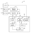
- FIG. 1 is a block diagram schematically showing an electrical configuration of the mobile terminal device 10.
- the mobile terminal device 10 is, for example, a mobile phone, a PDA, a smartphone, a tablet-type multifunctional mobile terminal device, or the like.
- the mobile terminal device 10 includes a backlight 11, a liquid crystal panel (an example of a display panel) 12, a touch panel 13, a liquid crystal panel drive circuit 14, a touch panel controller 15, a calculation unit 20, and the like.
- the backlight 11 is provided behind the liquid crystal panel 12, and illuminates the liquid crystal panel 12 from behind.
- the liquid crystal panel 12 is, for example, a TFT color liquid crystal panel, and displays a color image in accordance with a liquid crystal drive signal from the liquid crystal panel drive circuit 14.
- the liquid crystal panel drive circuit 14 receives display data Dd for displaying a color image from the arithmetic unit 20, generates a liquid crystal drive signal Sd including a data signal (gradation voltage) corresponding to the display data Dd, and outputs the liquid crystal drive signal. Sd is supplied to the liquid crystal panel 12.
- the touch panel 13 is disposed on the surface of the liquid crystal panel 12 on the user (observer) side, and generates a touch signal St including a touch point by the user as coordinate information. That is, the touch panel 13 is a coordinate detection type touch panel, and includes, for example, opposing transparent electrodes for the X coordinate and the Y coordinate. A transparent resistive film is formed on each transparent electrode. Touching each transparent resistive film with a finger or a pen or the like makes touch panel input, and a touch signal (voltage signal) corresponding to the X and Y coordinates. St is generated.
- the touch panel 13 has a handwriting input mode in which handwriting input is possible as an input mode.
- a touch panel controller 15 (an example of a touch panel control circuit) 15 supplies a reference voltage for detection to the touch panel 13.
- the touch panel controller 15 receives a touch signal St that is a divided voltage from the reference voltage from the touch panel 13.
- the touch signal St is converted into, for example, a digital coordinate signal Dz.
- the touch panel controller 15 receives the display data Dd from the arithmetic unit 20 and monitors the change of the display data Dd.
- the first touch signal (corresponding to the first touch signal) is received in a state in which the display data Dd does not change by a predetermined amount or more, and the first touch signal is received. 2
- the second touch signal is used as an effective input signal to the mobile terminal device.
- the touch panel controller 15 performs the second touch on the condition that the second touch signal is received within the second predetermined period from the reception of the first touch signal and the first touch signal.
- the signal is an effective input signal.
- the touch panel controller 15 may monitor the display data Dd by monitoring data in the image memory 15 as indicated by a broken line in FIG.
- the “predetermined amount” is a display data amount corresponding to a very small area on the liquid crystal panel 12 that is periodically updated, for example, a clock display.
- the state in which the display data Dd does not change by a predetermined amount or more can be said to be a display state of the liquid crystal panel 12 in which only such a clock display is periodically updated.
- the “first predetermined period” is, for example, 60 seconds.
- the “second predetermined period” is, for example, 3 seconds. Note that these “predetermined amount”, “first predetermined period”, and “second predetermined period” are examples, and may be appropriately changed according to user settings.
- the “effective input signal” means a signal that can cause the mobile terminal device to perform some operation. For example, it means a signal for starting a mobile terminal device in a power saving mode (sleep state).
- the calculation unit 20 performs overall control related to the image display of the mobile terminal device 10.
- the computing unit 20 includes a coordinate processing unit 21, an event determination processing unit 22, a display control processing unit 23, a backlight control processing unit 24, an image memory 25, a storage unit 26, and the like.
- the coordinate processing unit 21 receives the digital coordinate signal Dz from the touch panel controller 15 and performs coordinate processing using the digital coordinate signal Dz.
- the event determination processing unit 22 determines an event designated by the panel touch based on the coordinate-processed signal, and designates an application for executing the event.
- Various applications are stored in the storage unit 26 such as a hard disk.
- a display control processing unit (an example of a mode switching circuit) 23 generates display data Dd associated with execution of various applications and controls lighting of the backlight 11 via the backlight control processing unit 24. Specifically, the display control processing unit 23 switches between a display mode in which the backlight 11 is turned on and a power saving mode in which the backlight 11 is turned off.
- the “display mode” is a normal mode in which the user performs various applications.
- the “power saving mode” is a mode in which the mobile terminal device 10 is in a standby state. While the backlight 11 is turned off, the drive signal Sd from the liquid crystal panel drive circuit 14 to the liquid crystal panel 12 is stopped, and the liquid crystal panel 12 stops displaying images.
- the touch panel controller 15 switches from the display mode to the power saving mode when the state in which the display data Dd does not change by a predetermined amount or more continues for the first predetermined period or longer.
- the touch panel controller 15 receives the first touch signal St1 in the power saving mode and receives the second touch signal St2 within the second predetermined period from the reception of the first touch signal St1, the touch panel controller 15 switches from the power saving mode to the display mode.
- the display control processing unit 23 is controlled to switch to
- the image memory 25 is composed of, for example, a VRAM and is used when generating application display data Dd.
- the image memory 25 temporarily stores image data for at least one display screen of the liquid crystal panel 12.
- the storage unit 26 stores various programs executed by the arithmetic unit 20.
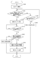
- FIG. 2 is a schematic flowchart relating to “touch panel input processing”.
- FIG. 3 is a schematic plan view showing touch points on the touch panel.
- the “touch panel input process” is executed at predetermined time intervals by the touch panel controller 15 according to a predetermined program.
- the touch panel controller 15 monitors whether the display data Dd has changed (step S100: YES).
- the touch panel controller 15 determines whether or not the state in which the display data Dd does not change by a predetermined amount or more continues for the first predetermined period (step S105).
- step S105 When it is determined that the state in which the display data Dd does not change by a predetermined amount or more continues for the first predetermined period (step S105: YES), the touch panel controller 15 controls the display control processing unit 23 to change the operation mode to the display mode. Is switched to the power saving mode (step S110). Next, in the power saving mode (after the first predetermined period), it is determined whether or not the touch signal (first touch signal) St1 of the first point P1 (see FIG. 3) has been received (step S115).
- step S115 When the first point touch signal St1 is received (step S115: YES), the second point P2 (see FIG. 3) touch signal (second touch signal) within the second predetermined period from the reception of the first point touch signal St1. ) It is determined whether or not St2 has been received (step S120).
- step S120 When it is determined that the second touch signal St2 is received within the second predetermined period (step S120: YES), the first touch signal St1 is invalidated and the second touch signal St2 is validated ( Step S130). In other words, the touch panel controller 15 regards the second touch signal St2 as a substantial first touch signal instead of the invalidated first touch signal St1.
- the touch panel controller 15 controls the display control processing unit 23 to switch from the power saving mode to the display mode, for example, as described above (step S135). ). Accordingly, the display control processing unit 23 turns on the backlight 11 and displays a predetermined image on the liquid crystal panel 12 via the liquid crystal panel drive circuit 14.
- the second touch signal St2 is invalidated (step S125).
- Step S105 when it is determined that the state in which the display data Dd does not change by a predetermined amount or more is not continued for the first predetermined period (Step S105: NO), the first touch signal St1 is received within the first predetermined period. It is determined whether or not (step S140). When the first touch signal St1 is received (step S140: YES), the first touch signal St1 is validated (step S145). Note that the process of step S140 is also performed when the first predetermined period has not elapsed since the display data Dd changed by a predetermined amount or more.
- the first touch point (coordinate) P ⁇ b> 1 and the second touch point (coordinate) P ⁇ b> 2 are arbitrary locations (coordinates) on the touch panel 13. Is done.
- the touch panel controller 15 detects the first touch signal (first touch) in a state in which the display data Dd does not change more than a predetermined amount for a first predetermined period or longer. Signal) St1, and when the second touch signal (second touch signal) St2 is received within the second predetermined period from the reception of the first touch signal St1, the first touch signal St1 is invalidated.
- the second touch signal St2 is used as an effective input signal to the mobile terminal device 10. Therefore, malfunction of the mobile terminal device 10 due to unnecessary contact with the touch panel 13 can be suppressed by a simple method.
- the touch panel controller 15 receives the first touch signal St1 in the power saving mode and receives the second touch signal St2 within the second predetermined period from the reception of the first touch signal St1.
- the display control processing unit 23 mode switching circuit
- the display control processing unit 23 is controlled to switch from the mode to the display mode. Therefore, it is suppressed that the backlight 11 is turned on by unnecessary contact with the touch panel 13. That is, it is possible to suppress unnecessary power consumption in the power saving mode. Further, when returning from the power saving mode to the display mode, it is not necessary to separately provide a switch for returning, and the user does not need to operate the switch.
- FIG. 4 is a schematic flowchart illustrating “touch panel input processing” according to the second embodiment.
- FIG. 5 is a schematic plan view showing touch points on the touch panel in the second embodiment. Since the second embodiment and the first embodiment are different only in the process related to the “touch panel input process”, only the difference from the first embodiment will be described below, and the same step number is assigned to the same process as the first embodiment. The description is omitted.
- the first touch signal St1 is generated according to the gesture pattern GP created by handwriting input, as shown in FIG. 5, instead of the input of the point P1. Further, user authentication processing is performed using the gesture pattern GP.
- the touch panel controller 15 changes the operation mode to the power saving mode when the state where the display data Dd does not change by a predetermined amount or more continues for the first predetermined period or longer (step S105: YES).
- the input mode of the touch panel 13 is set to the handwriting input mode (step S205).
- the 1st touch signal St1 according to handwriting input is received after progress of the 1st predetermined period, ie, when gesture pattern GP (refer FIG. 5) is input into the touch panel 13 (step S210: YES)
- handwriting An input authentication process is performed (step S215).
- the authentication process is performed, for example, by collating a handwritten input gesture pattern GP with a pre-registered gesture pattern.
- step S220 If the handwritten input gesture pattern GP is authenticated (step S220: YES), the processing from step S120 to step S135 is performed. On the other hand, when the gesture pattern GP is not authenticated (step S220: NO), the gesture pattern GP is invalidated (step S225). In step S130 in the second embodiment, the gesture pattern GP is invalidated only as a function of the first touch signal.
- step S105 when it is determined in step S105 that the state in which the display data Dd does not change by a predetermined amount or more is not continued for the first predetermined period (step S105: NO), one point within the first predetermined period is obtained as in the first embodiment. It is determined whether the eye touch signal St1 has been received (step S140). When the first touch signal St1 is received (step S140: YES), the first touch signal St1 is validated (step S145).
- a handwritten input gesture pattern GP is input.
- the gesture pattern GP is authenticated and the second touch signal St2 is input within the second predetermined period, the second touch signal St2 is validated and the operation mode is returned to the display mode.
- the second touch signal St2 is validated after the user is authenticated by the gesture pattern GP that is the first touch panel input. Therefore, malfunctions of the mobile terminal device 10 due to unnecessary contact with the touch panel 13 in the power saving mode or the like can be further suppressed. In addition, user authentication can be easily and suitably performed using the touch panel 13.
- the touch points P1 and P2 and the gesture pattern GP are formed on the touch panel 13 is arbitrary, but is not limited thereto.
- the touch points P ⁇ b> 1 and P ⁇ b> 2 and the gesture pattern GP may be formed in a predetermined area 13 ⁇ / b> A on the touch panel 13. That is, the touch panel 13 may include a predetermined touch area 13A for generating the first touch signal St1 and the second touch signal St2.
- the predetermined touch area 13 ⁇ / b> A is preferably set within a range in which the thumb can reach when the user holds the mobile terminal device 10 with one hand.
- the operation of returning from the power saving mode to the display mode can be performed with one thumb, and user operability is improved.
- the predetermined touch area 13B in FIG. 7 regardless of the holding direction of the mobile terminal device 10, that is, when the display screen is placed vertically (portrait mode), it is placed horizontally. In both cases (landscape mode), it is preferable that the range is within the reach of the thumb. In this case, user operability is further improved.
- the user may be allowed to set a predetermined area on the touch panel 13 at an arbitrary location.
- the predetermined touch area is not limited to one area on the touch panel 13.
- the touch point P1 or the gesture pattern GP may be formed in the first touch area 13C
- the touch point P2 may be formed in the second touch area 13D.
- the predetermined touch area may include a first touch area for generating the first touch signal St1 and a second touch area for generating the second touch signal St2.
- the user may be allowed to set the first and second touch areas at arbitrary locations on the touch panel 13.
- the second touch signal St2 is changed from the power saving mode in which the backlight 11 is turned off to the backlight.
- the second touch signal St2 may be an activation signal (trigger signal) for changing from a standby state during the display mode to an operation state.
- the touch panel controller 15 monitors the display data Dd, and receives the first touch signal St1 from the touch panel 13 in a state in which the display data Dd does not change more than a predetermined amount for a first predetermined period or longer.
- the second touch signal St2 is used as an effective input signal to the mobile terminal device 10 based on the reception of the second touch signal St2 from the touch panel 13 within the second predetermined period from the reception of the first touch signal St1. Any configuration may be used.
- FIG. 1 an example in which the touch panel controller 15 and the calculation unit 20 are configured differently has been shown, but the present invention is not limited thereto, and the touch panel controller (touch panel control circuit) It is good also as a structure contained in the calculating part 20.
- FIG. 1 the “touch panel input process” illustrated in FIGS. 2 and 4 is performed by the arithmetic unit (an example of a touch panel control circuit) 20.
- the input mode of the touch panel 13 may be set to the handwriting input mode.
- the touch point P1 and the touch point P2 can be an arbitrary registered pattern instead of a point, and malfunction due to unnecessary contact with the touch panel 13 can be further suppressed.
- the mobile terminal device provided with the liquid crystal panel as the display panel has been exemplified.
- the present invention can also be applied to other types of display panels, for example, mobile terminal devices provided with an EL panel. is there.
Landscapes
- Engineering & Computer Science (AREA)
- General Engineering & Computer Science (AREA)
- Theoretical Computer Science (AREA)
- Human Computer Interaction (AREA)
- Physics & Mathematics (AREA)
- General Physics & Mathematics (AREA)
- Position Input By Displaying (AREA)
Abstract
Le présent dispositif terminal portable comporte : un panneau d'affichage ; un panneau tactile servant à générer un signal de toucher représentant un point de toucher sous forme de coordonnées, le panneau tactile étant agencé sur une surface du côté de l'observateur du panneau d'affichage ; et un circuit de commande du panneau tactile. Le circuit de commande du panneau tactile surveille les données d'affichage fournies au panneau d'affichage ; reçoit un premier signal de toucher du panneau tactile (« OUI » en S115) quand un état dans lequel les données d'affichage ne changent pas d'une quantité supérieure ou égale à une quantité prédéterminée est maintenu pendant une première période prédéterminée ou plus (« OUI » dans S105) ; et utilise un second signal de toucher comme signal d'entrée effectif vers le dispositif terminal portable (S130) sur la base de la réception du second signal de toucher du panneau tactile dans une seconde période prédéterminée à partir de la réception du premier signal de toucher (« OUI » dans S120).
Applications Claiming Priority (2)
| Application Number | Priority Date | Filing Date | Title |
|---|---|---|---|
| JP2011-089294 | 2011-04-13 | ||
| JP2011089294 | 2011-04-13 |
Publications (1)
| Publication Number | Publication Date |
|---|---|
| WO2012141083A1 true WO2012141083A1 (fr) | 2012-10-18 |
Family
ID=47009258
Family Applications (1)
| Application Number | Title | Priority Date | Filing Date |
|---|---|---|---|
| PCT/JP2012/059458 Ceased WO2012141083A1 (fr) | 2011-04-13 | 2012-04-06 | Dispositif terminal portable et son procédé de commande |
Country Status (1)
| Country | Link |
|---|---|
| WO (1) | WO2012141083A1 (fr) |
Cited By (3)
| Publication number | Priority date | Publication date | Assignee | Title |
|---|---|---|---|---|
| JP2014194643A (ja) * | 2013-03-28 | 2014-10-09 | Fujitsu Ltd | 情報処理装置,情報処理方法及び情報処理プログラム |
| JP2016537757A (ja) * | 2013-11-05 | 2016-12-01 | グーグル インコーポレイテッド | 電子デバイスのための方向タッチアンロック |
| JP2017021536A (ja) * | 2015-07-09 | 2017-01-26 | 富士通株式会社 | 電子機器および点灯制御プログラム |
Citations (5)
| Publication number | Priority date | Publication date | Assignee | Title |
|---|---|---|---|---|
| JP2002082734A (ja) * | 2000-09-06 | 2002-03-22 | Sony Corp | 情報処理装置、情報処理方法、並びにプログラム格納媒体 |
| JP2004274570A (ja) * | 2003-03-11 | 2004-09-30 | Matsushita Electric Ind Co Ltd | 携帯機器におけるキーバックライトの制御方法 |
| JP2008257427A (ja) * | 2007-04-04 | 2008-10-23 | Nikon Corp | 電子機器およびカメラ |
| JP2009521753A (ja) * | 2005-12-23 | 2009-06-04 | アップル インコーポレイテッド | アンロック画像上でジェスチャを行うことによる機器のアンロッキング |
| JP2010098653A (ja) * | 2008-10-20 | 2010-04-30 | Ricoh Co Ltd | 画像処理装置、画像形成装置、省電力状態からの復帰方法、及びコンピュータプログラム |
-
2012
- 2012-04-06 WO PCT/JP2012/059458 patent/WO2012141083A1/fr not_active Ceased
Patent Citations (5)
| Publication number | Priority date | Publication date | Assignee | Title |
|---|---|---|---|---|
| JP2002082734A (ja) * | 2000-09-06 | 2002-03-22 | Sony Corp | 情報処理装置、情報処理方法、並びにプログラム格納媒体 |
| JP2004274570A (ja) * | 2003-03-11 | 2004-09-30 | Matsushita Electric Ind Co Ltd | 携帯機器におけるキーバックライトの制御方法 |
| JP2009521753A (ja) * | 2005-12-23 | 2009-06-04 | アップル インコーポレイテッド | アンロック画像上でジェスチャを行うことによる機器のアンロッキング |
| JP2008257427A (ja) * | 2007-04-04 | 2008-10-23 | Nikon Corp | 電子機器およびカメラ |
| JP2010098653A (ja) * | 2008-10-20 | 2010-04-30 | Ricoh Co Ltd | 画像処理装置、画像形成装置、省電力状態からの復帰方法、及びコンピュータプログラム |
Cited By (3)
| Publication number | Priority date | Publication date | Assignee | Title |
|---|---|---|---|---|
| JP2014194643A (ja) * | 2013-03-28 | 2014-10-09 | Fujitsu Ltd | 情報処理装置,情報処理方法及び情報処理プログラム |
| JP2016537757A (ja) * | 2013-11-05 | 2016-12-01 | グーグル インコーポレイテッド | 電子デバイスのための方向タッチアンロック |
| JP2017021536A (ja) * | 2015-07-09 | 2017-01-26 | 富士通株式会社 | 電子機器および点灯制御プログラム |
Similar Documents
| Publication | Publication Date | Title |
|---|---|---|
| US8269754B2 (en) | Portable terminal, display control program, and display control method | |
| JP5519871B1 (ja) | 携帯電子機器 | |
| US10884690B2 (en) | Dual screen device having power state indicators | |
| EP2474887B1 (fr) | Procédés et appareil de correction d'erreur de saisie pour appareil d'entrée | |
| CN103377004B (zh) | 操作显示装置以及操作显示方法 | |
| JP5813353B2 (ja) | 携帯端末、表示装置、輝度制御方法及び輝度制御プログラム | |
| US20150116232A1 (en) | Portable information terminal | |
| KR20100081152A (ko) | 전자 기기에서 디스플레이 방법 및 장치 | |
| JP5780438B2 (ja) | 電子機器、位置指定方法及びプログラム | |
| US20150153850A1 (en) | Electronic device, display control method and storage medium | |
| WO2011040165A1 (fr) | Dispositif de traitement d'informations, procédé de traitement d'informations et programme | |
| CN103558954A (zh) | 一种触摸系统及显示装置 | |
| JP2015125567A (ja) | 電子機器、方法及びプログラム | |
| US20110254784A1 (en) | Controlling method and information processing apparatus | |
| EP2889730B1 (fr) | Dispositif d'affichage, appareil électronique et procédé de commande de plage d'éclairage pour dispositif d'affichage | |
| JP2014215749A (ja) | 電子機器、制御方法およびプログラム | |
| CN111638810A (zh) | 触控方法、装置及电子设备 | |
| JP6177613B2 (ja) | 端末装置および端末装置の制御方法 | |
| WO2013046983A1 (fr) | Terminal de traitement d'informations et son procédé de commande d'affichage | |
| US20140282226A1 (en) | Electronic Apparatus, Display Control Method and Storage Medium | |
| JP7661819B2 (ja) | タッチパネル | |
| JP2012181412A (ja) | 表示装置及び電子機器、表示装置の点灯範囲制御方法 | |
| JP5001796B2 (ja) | タッチパネル装置 | |
| JP2012243232A (ja) | タッチパネル装置 | |
| WO2021193633A1 (fr) | Appareil d'entrée tactile et programme |
Legal Events
| Date | Code | Title | Description |
|---|---|---|---|
| 121 | Ep: the epo has been informed by wipo that ep was designated in this application |
Ref document number: 12771553 Country of ref document: EP Kind code of ref document: A1 |
|
| NENP | Non-entry into the national phase |
Ref country code: DE |
|
| 122 | Ep: pct application non-entry in european phase |
Ref document number: 12771553 Country of ref document: EP Kind code of ref document: A1 |
|
| NENP | Non-entry into the national phase |
Ref country code: JP |