WO2012141237A1 - Pale de rotor d'éolienne - Google Patents
Pale de rotor d'éolienne Download PDFInfo
- Publication number
- WO2012141237A1 WO2012141237A1 PCT/JP2012/059987 JP2012059987W WO2012141237A1 WO 2012141237 A1 WO2012141237 A1 WO 2012141237A1 JP 2012059987 W JP2012059987 W JP 2012059987W WO 2012141237 A1 WO2012141237 A1 WO 2012141237A1
- Authority
- WO
- WIPO (PCT)
- Prior art keywords
- outer skin
- divided
- skin
- wind turbine
- turbine blade
- Prior art date
- Legal status (The legal status is an assumption and is not a legal conclusion. Google has not performed a legal analysis and makes no representation as to the accuracy of the status listed.)
- Ceased
Links
Images








Classifications
-
- F—MECHANICAL ENGINEERING; LIGHTING; HEATING; WEAPONS; BLASTING
- F03—MACHINES OR ENGINES FOR LIQUIDS; WIND, SPRING, OR WEIGHT MOTORS; PRODUCING MECHANICAL POWER OR A REACTIVE PROPULSIVE THRUST, NOT OTHERWISE PROVIDED FOR
- F03D—WIND MOTORS
- F03D1/00—Wind motors with rotation axis substantially parallel to the air flow entering the rotor
- F03D1/06—Rotors
- F03D1/065—Rotors characterised by their construction elements
- F03D1/0675—Rotors characterised by their construction elements of the blades
-
- F—MECHANICAL ENGINEERING; LIGHTING; HEATING; WEAPONS; BLASTING
- F03—MACHINES OR ENGINES FOR LIQUIDS; WIND, SPRING, OR WEIGHT MOTORS; PRODUCING MECHANICAL POWER OR A REACTIVE PROPULSIVE THRUST, NOT OTHERWISE PROVIDED FOR
- F03D—WIND MOTORS
- F03D13/00—Assembly, mounting or commissioning of wind motors; Arrangements specially adapted for transporting wind motor components
- F03D13/10—Assembly of wind motors; Arrangements for erecting wind motors
-
- F—MECHANICAL ENGINEERING; LIGHTING; HEATING; WEAPONS; BLASTING
- F03—MACHINES OR ENGINES FOR LIQUIDS; WIND, SPRING, OR WEIGHT MOTORS; PRODUCING MECHANICAL POWER OR A REACTIVE PROPULSIVE THRUST, NOT OTHERWISE PROVIDED FOR
- F03D—WIND MOTORS
- F03D13/00—Assembly, mounting or commissioning of wind motors; Arrangements specially adapted for transporting wind motor components
- F03D13/40—Arrangements or methods specially adapted for transporting wind motor components
-
- F—MECHANICAL ENGINEERING; LIGHTING; HEATING; WEAPONS; BLASTING
- F05—INDEXING SCHEMES RELATING TO ENGINES OR PUMPS IN VARIOUS SUBCLASSES OF CLASSES F01-F04
- F05B—INDEXING SCHEME RELATING TO WIND, SPRING, WEIGHT, INERTIA OR LIKE MOTORS, TO MACHINES OR ENGINES FOR LIQUIDS COVERED BY SUBCLASSES F03B, F03D AND F03G
- F05B2240/00—Components
- F05B2240/20—Rotors
- F05B2240/30—Characteristics of rotor blades, i.e. of any element transforming dynamic fluid energy to or from rotational energy and being attached to a rotor
- F05B2240/302—Segmented or sectional blades
-
- F—MECHANICAL ENGINEERING; LIGHTING; HEATING; WEAPONS; BLASTING
- F05—INDEXING SCHEMES RELATING TO ENGINES OR PUMPS IN VARIOUS SUBCLASSES OF CLASSES F01-F04
- F05B—INDEXING SCHEME RELATING TO WIND, SPRING, WEIGHT, INERTIA OR LIKE MOTORS, TO MACHINES OR ENGINES FOR LIQUIDS COVERED BY SUBCLASSES F03B, F03D AND F03G
- F05B2260/00—Function
- F05B2260/30—Retaining components in desired mutual position
- F05B2260/301—Retaining bolts or nuts
-
- Y—GENERAL TAGGING OF NEW TECHNOLOGICAL DEVELOPMENTS; GENERAL TAGGING OF CROSS-SECTIONAL TECHNOLOGIES SPANNING OVER SEVERAL SECTIONS OF THE IPC; TECHNICAL SUBJECTS COVERED BY FORMER USPC CROSS-REFERENCE ART COLLECTIONS [XRACs] AND DIGESTS
- Y02—TECHNOLOGIES OR APPLICATIONS FOR MITIGATION OR ADAPTATION AGAINST CLIMATE CHANGE
- Y02E—REDUCTION OF GREENHOUSE GAS [GHG] EMISSIONS, RELATED TO ENERGY GENERATION, TRANSMISSION OR DISTRIBUTION
- Y02E10/00—Energy generation through renewable energy sources
- Y02E10/70—Wind energy
- Y02E10/72—Wind turbines with rotation axis in wind direction
-
- Y—GENERAL TAGGING OF NEW TECHNOLOGICAL DEVELOPMENTS; GENERAL TAGGING OF CROSS-SECTIONAL TECHNOLOGIES SPANNING OVER SEVERAL SECTIONS OF THE IPC; TECHNICAL SUBJECTS COVERED BY FORMER USPC CROSS-REFERENCE ART COLLECTIONS [XRACs] AND DIGESTS
- Y02—TECHNOLOGIES OR APPLICATIONS FOR MITIGATION OR ADAPTATION AGAINST CLIMATE CHANGE
- Y02P—CLIMATE CHANGE MITIGATION TECHNOLOGIES IN THE PRODUCTION OR PROCESSING OF GOODS
- Y02P70/00—Climate change mitigation technologies in the production process for final industrial or consumer products
- Y02P70/50—Manufacturing or production processes characterised by the final manufactured product
Definitions
- the present invention relates to a wind turbine blade.
- wind power generators have become larger in order to improve power generation efficiency and increase power generation.
- the wind turbine blades also become larger.
- the blade length is 40 meters or more and the maximum blade width is more than 4 meters.
- the blade length and blade width tend to be larger.
- various problems in production and transportation arise. That is, in order to reduce the weight of the wind turbine blade, for example, it is manufactured from plastic reinforced with fibers, but when the sheet to be manufactured is enlarged, fiber wrinkles, resin non-impregnated defects, poor adhesion, etc. during manufacture There is a risk that the production defects will be increased and the product quality will be reduced. In addition, the manufacturing time becomes longer.
- the present invention provides a wind turbine blade capable of suppressing manufacturing and transportation restrictions, reducing weight, and suppressing deterioration of performance and noise.
- One aspect of the present invention is a wind turbine blade comprising an outer skin that forms a long hollow space having an airfoil in cross section, and a girder that is longitudinally reinforced to reinforce the outer skin from the inside.
- the blade root side portion of the outer skin is divided into an outer skin body including a front edge in the width direction and a divided outer skin including a rear edge, and the divided outer skin is movable in the longitudinal direction with respect to the outer skin body.
- it is a windmill blade attached to the said girder.
- the wind turbine blade since it is manufactured by the unit of the outer skin main body and the divided outer skin divided in the width direction, it can be manufactured easily, inexpensively and with high quality as compared with those manufactured integrally. Can do. Since it is conveyed by the manufactured unit, the constraint condition in the width direction is relaxed. As a result, securing a transport vehicle, selecting a road, and the like are facilitated and efficient transport can be performed, so that the transport work time and cost can be reduced.
- the split outer skin is attached to the outer skin body or the girder so as to be movable in the longitudinal direction with respect to the outer skin body. For example, it is attached so as not to move relatively in the width direction. Therefore, even if the outer shell body and the girder are deformed so as to expand and contract in the longitudinal direction during operation, the split outer shell moves relative to the longitudinal direction, so that it is possible to prevent the longitudinal load from acting on the split outer shell. Can do. Thereby, since the structure of a division
- the divided skin does not move relative to the skin body in the width direction, it is possible to suppress performance and noise degradation.
- a part of the outer surface of the wind turbine blade is damaged, it is only necessary to replace the outer skin main body or the divided outer skin where the damaged portion exists, so that the restoration is easier and cheaper than when the whole is replaced. it can.
- the head of the joint member should not protrude from the outer surface of the outer skin body or the split skin, in other words, the outer surface with the split skin being joined by the joint member. Is preferably smooth. If it does in this way, degradation of performance and noise can be controlled further.
- the divided outer skin may be adapted to overlap each other and the outer skin body facing the width direction. If it does in this way, a division
- the split skin may be provided with split skin girders that are vertically run in the longitudinal direction and reinforce the split skin from the inside. In this way, the strength can be maintained even if the divided skin is thinned. Thereby, since the deformation
- At least the main body skin and the beam may be divided in the longitudinal direction.
- the manufacturing unit can be made smaller, it is possible to manufacture easily, inexpensively and with high quality as compared with a unit manufactured integrally. Since it is conveyed by the manufactured unit, the constraint condition in the longitudinal direction is relaxed. As a result, securing a transport vehicle, selecting a road, and the like are facilitated and efficient transport can be performed, so that the transport work time and cost can be reduced. If the manufactured unit is small, the weight of each unit becomes lighter, so that handling at the time of repair including replacement becomes easier.
- the divided skin may be constituted by a partially divided skin divided in the longitudinal direction, and the partially divided skins may be movably attached to each other. In this way, since the joining portions split skin is not fixed, it is possible to prevent such an excessive load to a particular junction.
- the divided skin may be constituted by partially divided skins divided in the longitudinal direction, and the partially divided skins may be attached so as to be fixed by a coupling means. If it does in this way, since there is no sliding part between partial division
- a drain hole that connects the space and the external space may be formed at a rear edge side end portion of the divided skin. If there is ingress of water due to rain within the structure of the wind turbine blade, it can be discharged to the outside of the water from the drain vent hole. Thus, since the drain hole is provided in the division
- the divided skin portion may be attached by a conductive coupling member, and at least a part of the coupling member may be connected to a main body ground installed in the space by a ground wire.
- a lightning strike occurs in the coupling member and the vicinity thereof, a lightning current can be passed to the main body ground via the coupling member and the ground wire, so that it is possible to prevent damage to the divided outer skin and the like due to the lightning stroke.
- the present invention since it is manufactured in units of the outer skin main body and the divided outer skin divided in the width direction, it can be manufactured easily, inexpensively and with high quality as compared with those manufactured integrally. Since it is transported in the manufactured unit, it is possible to shorten the transportation work time and the cost.
- the split outer skin is attached to the outer skin main body or girders so that it can move in the longitudinal direction with respect to the outer skin main body, so that the structure of the split outer skin can be simplified and the weight can be reduced, and the wind turbine blades can be reduced in weight.
- the divided outer skin does not move relative to the outer skin main body in the width direction, it is possible to suppress deterioration of performance and noise. When a part of the outer surface of the wind turbine blade is damaged, it is only necessary to replace the outer skin main body or the divided outer skin where the damaged portion exists, so that the restoration is easier and cheaper than when the whole is replaced. it can.
- FIG. 3 is a sectional view taken along line XX in FIG. 2. It is a fragmentary sectional view which expands and shows the Y section of FIG.
- FIG. 5 is a partial plan view of FIG. 4. It is explanatory drawing which shows the fastening state of FIG. It is a fragmentary top view which shows the fastening part of FIG. It is a fragmentary sectional view which shows another aspect of the coupling
- FIG. 13 is a ZZ sectional view of FIG. 12. It is sectional drawing which shows the windmill blade concerning 4th embodiment of this invention. It is sectional drawing which shows the principal part of the windmill blade concerning other embodiment of this invention. It is an AA arrow line view which shows the principal part of the windmill blade concerning other embodiment of this invention.
- FIG. 1 is a side view showing an overall schematic configuration of the wind turbine generator 1.
- the wind power generator 1 includes a support column 5 standing on the foundation 3, a nacelle 7 installed at the upper end of the support column 5, and a nacelle 7 that can rotate around a substantially horizontal axis. And a plurality of, for example, three wind turbine blades 11 attached radially around the rotation axis of the rotor head 9.
- the wind force that hits the wind turbine blades 11 from the direction of the rotation axis of the rotor head 9 is converted into power that rotates the rotor head 9 about the rotation axis.
- a generator connected to the rotor head 9 via a coaxial gearbox is installed inside the nacelle 7, although not shown in the drawings. That is, by rotating the rotor head 9 with a speed increaser and driving the power generator, an electrical output can be obtained from the power generator.
- FIG. 2 is a perspective view showing the wind turbine blade 11.
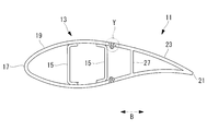
- 3 is a cross-sectional view taken along the line XX of FIG.
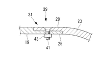
- FIG. 4 is an enlarged partial cross-sectional view showing a Y portion in FIG.
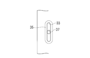
- FIG. 5 is a partial plan view of FIG.
- the wind turbine blade 11 includes a skin 13 that defines a long hollow blade shape, and a plurality of, for example, two main girders (girder) that are longitudinally passed in the longitudinal direction L inside the skin and reinforce the strength of the skin 13. 15).
- the main girder 15, 15 are respectively cross-sectional shape is a U-shaped, mounted in the form of its open portion facing.
- the main girders 15 and 15 are made of, for example, glass fiber reinforced plastic. As these materials, for example, carbon fiber reinforced plastics or other materials may be used.
- the outer skin 13 includes an outer skin body 19 including a front edge 17 and a divided outer skin 23 including a rear edge 21.
- the divided skin 23 is installed on the blade root side portion of the skin 13. Therefore, the blade root side portion of the outer skin 13 is divided into two in the width direction B into an outer skin body 19 including the front edge 17 and a divided outer skin 23 including the rear edge 21.
- the outer skin body 19 and the divided outer skin 23 are made of, for example, fiber reinforced plastic (FRP) reinforced with fibers such as glass fiber reinforced plastic or carbon fiber reinforced plastic.
- FRP fiber reinforced plastic
- Skin body 19 two halves of the back skin and the front skin is formed by bonding.
- the position corresponding to the divided outer skin 23 of the outer skin main body 19 forms an open portion with the rear edge 21 side end projecting toward the rear edge 21 rather than the main girder 15 on the rear edge 21 side. That is, the outer skin body 19 is reinforced by the main girders 15 and 15.
- a main body coupling portion 25 in which a part on the inner surface side protrudes in a rectangular cross section is provided at a rear edge 21 side end portion of the outer skin body 19 at a position corresponding to the divided skin 23.
- the divided skin 23 has a structure in which two halves of a back skin and a ventral skin are joined by a rear edge 21 and the front edge 17 side is open.
- the split skin 23 is provided with a split skin girder 27 extending in the longitudinal direction L at an intermediate position in the width direction B in order to reinforce the structure from the inside.
- the shape of the split outer shell 23 can be maintained even if the dorsal and ventral outer shells forming the outer shape of the split outer shell 23 are thinned, and they are deformed even when a load is applied. Can be suppressed.
- Split skin girder 27, when the split outer skin 23 is configured to have a necessary strength may be omitted.
- a split coupling portion 29 in which a part on the outer surface side protrudes in a rectangular cross section is provided at the end portion on the front edge 17 side of the split skin 23.
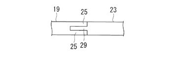
- the main body coupling portion 25 and the split coupling portion 29 are overlapped as shown in FIG.
- segmentation outer skin 23 is made to overlap with the outer skin main body 19 which opposes the width direction B mutually.
- the height from the outer surface of the outer skin main body 19 to the main body coupling portion 25 and the thickness of the split coupling portion 29 are the coupling portion 31, and the outer surface of the split coupling portion 29 is flush with the outer surface of the outer skin body 19. It is made the size. In this way, by adjusting the depth of the main body coupling portion 25 and the thickness of the division coupling portion 29, the outer surface of the divided outer skin 23 and the outer surface of the outer skin main body 19 are coupled so as not to have a step. be able to.
- a plurality of long holes 33 that are long in the longitudinal direction L are provided in the split coupling portion 29 at intervals in the longitudinal direction L.
- the distance between the adjacent long holes 33 is set to be twice or more the distance K1 from the front edge 17 side end of the split coupling portion 29 to the long hole 33.
- a peripheral portion of the long hole 33 is an inclined surface 35.
- the body coupling portion 25, at a position corresponding to the long hole 33, the hole 37 of the cylindrical shape is formed so as to penetrate in the thickness direction.
- the main body coupling portion 25 and the split coupling portion 29 are configured to be coupled by a coupling member 39.
- the coupling member 39 includes a bolt 41 and a nut 43 that is screwed into the bolt 41.
- the bolt 41 is provided with a shaft portion 45 and a head portion 47 which are male threaded.
- the diameter of the shaft portion 45 is substantially equal to the length B in the width direction of the long hole 33 and the diameter of the hole 37.
- the upper surface of the head 47 is flat, and the lower surface is inclined so as to engage with the inclined surface 35.
- the outer skin main body 19 and the divided outer skin 23 are arranged such that the main body coupling portion 25 and the divided coupling portion 29 are in a relationship such that the long hole 33 and the hole 37 coincide with each other. 4 and is connected as shown in FIG. 4 by screwing a nut 43 into the bolt 41.
- the divided skin 29 can move in the longitudinal direction L with respect to the skin body 19. it can.
- the main body coupling portion 25 and the split coupling portion 29 project in a rectangular cross section and are stacked one above the other.
- the present invention is not limited to this.
- the main body coupling portion 25 may be provided on the outer side and the inner side of the outer skin main body 19 so as to sandwich the split coupling portion 29 provided at an intermediate position in the thickness direction.
- the opposing surfaces of the main body coupling portion 25 and the split coupling portion 29 may be inclined surfaces and may be engaged in a wedge shape.
- the wind turbine blade 11 configured as described above is manufactured easily, inexpensively, and with high quality as compared with the one manufactured integrally because the outer shell body 19 and the divided outer shell 23 are independently manufactured. Can do. That is, the mold for manufacturing the outer skin main body 19 and the divided outer skin 23 can be made compact. For this reason, since quality control can fully be performed, the quality of a product improves. Since the amount of waste due to manufacturing errors is reduced, the product yield is improved. Moreover, the place which manufacture requires can be made small.
- the manufactured outer skin body 19 and the divided outer skin 23 are transported to the installation location of the wind turbine generator 1. At this time, the outer skin main body 19 or the divided outer skin 23 is smaller in length in the width direction B and smaller in weight than the integrated wind turbine blade 11, so that it is easy to secure a transport vehicle, select a road, and the like. . Thereby, since efficient conveyance can be performed, the conveyance work time can be shortened and the cost can be reduced.
- the outer skin main body 19 and the divided outer skin 23 transported to the installation place are connected by a coupling member 39 to form a wind turbine blade 11 and attached to the rotor head 9.
- the main body outer skin 19 and the main girders 15 and 15 are long in the longitudinal direction L, the main body outer skin 19 and the main girders 15 and 15 may be divided in the longitudinal direction L.
- the manufacturing unit can be made smaller, it is possible to manufacture easily, inexpensively and with high quality as compared with a unit manufactured integrally. Since it is conveyed by the manufactured unit, the constraint condition in the longitudinal direction is relaxed. As a result, securing a transport vehicle, selecting a road, and the like are facilitated and efficient transport can be performed, so that the transport work time and cost can be further reduced.
- the wind turbine blade 11 When the wind turbine generator 1 manufactured in this way is operated, the wind turbine blade 11 receives wind pressure and bends greatly so that the tip is directed to the downstream side of the wind direction as shown by a two-dot chain line in FIG. Moreover, when receiving wind and rotating, it receives a tensile load due to centrifugal force. As a result, the wind turbine blade 11 is greatly expanded or contracted in the longitudinal direction L, that is, bent and deformed. Therefore, the outer skin body 19 and the main girders 15 and 15 are deformed so as to expand and contract in the longitudinal direction L.
- the coupling member 39 moves in the longitudinal direction L along the long hole 33 of the divided skin 23, in other words, Since the outer skin body 19 and the divided skin 23 are relatively moved in the longitudinal direction L, it is possible to prevent the load in the longitudinal direction L from acting on the divided skin 23. Thereby, since the structure of the division
- the length K in the axial direction L of the plurality of long holes 33 is calculated by analyzing the maximum strain in the longitudinal direction L of the outer skin main body 19 at the position of each long hole 33. It may be a size that can cover. In this way, the length K of each elongated hole 33 is not unnecessarily increased, so that the strength of the divided outer shell 23 can be increased or the weight can be further reduced. Further, by analysis, the maximum strain in the longitudinal direction L of the outer skin main body 19 at the position of each long hole 33 is calculated, and the largest of the calculated maximum strains is set as the length K of the long hole 33. May be. If it does in this way, since all the length of the long hole 33 can be made into the same thing, it can construct easily.
- the shaft portion 45 of the bolt 41 has a diameter substantially equal to the length B in the width direction of the long hole 33, the bolt 41 does not move in the width direction B of the long hole 33. That is, since the split outer skin 23 does not move relative to the outer skin body 19 in the width direction B, it is possible to suppress degradation of the aerodynamic performance and noise of the wind turbine blade 11.
- the shaft portion 45 of the bolt 41 has a diameter substantially equal to the length B in the width direction of the long hole 33, the bolt 41 does not move in the width direction B of the long hole 33. That is, since the split outer skin 23 does not move relative to the outer skin body 19 in the width direction B, it is possible to suppress degradation of the aerodynamic performance and noise of the wind turbine blade 11.
- the outer shell body 19 or the divided outer shell 23 in which the damaged portion is present so that the recovery is easier than when the entire wind turbine blade 11 is replaced. Can be done inexpensively.
- the head 47 of the bolt 41 does not protrude from the outer surface of the outer skin main body 19 or the divided outer skin 23, in other words, the outer surface is made smooth in a state where the divided outer skin 23 is coupled by the coupling member 39, And since the division
- the split outer skin 23 is attached to the outer skin main body 19, but it may be attached to the main beam 15 as shown in FIG. 10.
- the outer skin body 19 has a size up to the main girder 15 on the rear edge 21 side in the width direction B, and the end portion on the rear edge 21 side is a substantially vertical surface.
- segmentation outer skin 23 is made into the magnitude
- the front edge 17 side edge part is made into the substantially perpendicular
- a long hole 33 shown in FIG. 5 is formed in the split outer shell 23, and a hole 37 shown in FIG. 7 is formed in the main girder 15.
- the split outer shell 23 is joined to the main girder 15 by a connecting member 39. Has been. In this way, the divided outer skin 23 is attached to the main girder 15 which is stronger than the outer skin main body 19, so that the reliability of the coupling structure can be improved.
- FIG. 11 is a perspective view showing the wind turbine blade 11 according to the present embodiment.
- the divided skin 23 is composed of a plurality of, for example, three partially divided skins 49 divided in the longitudinal direction L.
- the partially divided outer skins 49 are coupled to each other by a coupling member 51.
- the coupling member 51 is coupled so as to suppress the partial division outer skins 49 from moving with respect to each other. Thereby, the division
- the divided skins 23 are formed by manufacturing the three partially divided skins 49 and connecting them by the joining member 51 at the manufacturing factory or the installation location of the wind power generator 1.
- the unit for manufacturing the split outer shell 23 is smaller than the partial split outer shell 49, so that it can be manufactured more easily, inexpensively and with high quality.
- the partial replaceability is further improved and the transportation becomes easier.
- FIG. 12 is a side view showing the divided skin 23 according to the present embodiment.
- FIG. 13 is a ZZ cross-sectional view of FIG.
- a drain hole 55 that connects the internal space (space) 53 and the external space is formed at the end portion of the divided skin 23 on the rear edge 21 side.
- the drain hole 55 is for discharging water to the outside when water enters the structure inside the wind turbine blade 11 due to rain or the like.
- the drain hole 55 is provided in the divided outer shell 23, the drain hole 55 can be easily processed. Even if a defect occurs in the drain hole 55, it is only necessary to replace the split outer shell 23, so that the replacement is easy.
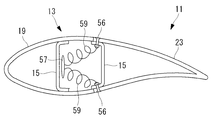
- FIG. 14 is a cross-sectional view showing the wind turbine blade 11 according to the present embodiment.
- segmentation outer skin 23 is attached to the main beam 15 with the coupling member 56, as FIG. 10 shows.
- the coupling member 39 is made of a conductive material, for example, a metal.
- the coupling member 39 may be a conductive material and may be made of resin.
- the front edge 17 side of the main beam 15, the main body ground wire (body earth) 57 over substantially the entire length is attached.
- the plurality of coupling members 39, and at least a portion of the bonding member 39 body ground wire 57 are connected by the ground wire 59.
- the present invention is not limited to the above embodiments may be appropriately modified within a scope not departing from the gist thereof.
- the partially divided outer skins 49 are attached to each other so as to be movable. If it does in this way, since joining of partial division skin 49 is not fixed, it can prevent that an excessive load is applied to a specific joined part.
- reference numeral 71 is a bolt
- reference numeral 72 is a nut
- reference numeral 73 is a through hole provided in one partial division outer skin 49
- reference numeral 74 is a through hole provided in the other partial division outer skin 49. It is.
- Each of the through holes 73 and 74 is a round hole having a circular shape in plan view, and the through hole 73 is formed so that the inner diameter thereof is larger than the inner diameter of the through hole 74.
- Windmill blade 13 Outer skin 15 Main girder 17 Front edge 19 Outer skin main body 21 Rear edge 23 Divided outer skin 27 Divided outer girder 49 Partially divided outer skin 53 Internal space 55 Drain hole 57 Main body ground wire 59 Ground wire
Landscapes
- Engineering & Computer Science (AREA)
- Life Sciences & Earth Sciences (AREA)
- Sustainable Development (AREA)
- Sustainable Energy (AREA)
- Chemical & Material Sciences (AREA)
- Combustion & Propulsion (AREA)
- Mechanical Engineering (AREA)
- General Engineering & Computer Science (AREA)
- Wind Motors (AREA)
Abstract
L'invention porte sur une pale de rotor d'éolienne configurée de telle sorte que les limitations affectant la fabrication et le transport de la pale sont réduites, que la pale est légère et que la réduction de la performance et l'accroissement du bruit peuvent être réduits. Une pale de rotor d'éolienne (11) comprend : une peau extérieure (13) qui forme un espace creux allongé ayant une coupe transversale en forme d'aile ; et une poutre principale (15) insérée dans la direction longitudinale et qui renforce la peau extérieure (13) par l'intérieur. La partie côté pied de la pale de la peau extérieure (13) est divisée par un plan transversal en un corps de peau extérieure (19) qui comprend un bord d'attaque (17) et une peau extérieure divisée (23) qui comprend un bord de fuite (31). La peau extérieure divisée (23) est attachée soit au corps de peau extérieure (19), soit à la poutre principale (15) de manière à pouvoir se déplacer dans la direction longitudinale par rapport au corps de peau extérieure (19).
Applications Claiming Priority (2)
| Application Number | Priority Date | Filing Date | Title |
|---|---|---|---|
| JP2011-090955 | 2011-04-15 | ||
| JP2011090955A JP5709628B2 (ja) | 2011-04-15 | 2011-04-15 | 風車翼 |
Publications (1)
| Publication Number | Publication Date |
|---|---|
| WO2012141237A1 true WO2012141237A1 (fr) | 2012-10-18 |
Family
ID=47009404
Family Applications (1)
| Application Number | Title | Priority Date | Filing Date |
|---|---|---|---|
| PCT/JP2012/059987 Ceased WO2012141237A1 (fr) | 2011-04-15 | 2012-04-12 | Pale de rotor d'éolienne |
Country Status (2)
| Country | Link |
|---|---|
| JP (1) | JP5709628B2 (fr) |
| WO (1) | WO2012141237A1 (fr) |
Cited By (1)
| Publication number | Priority date | Publication date | Assignee | Title |
|---|---|---|---|---|
| US20240401559A1 (en) * | 2023-06-05 | 2024-12-05 | Wind Harvest International Inc | Fairing System for a Vertical Axis Wind Turbine |
Families Citing this family (1)
| Publication number | Priority date | Publication date | Assignee | Title |
|---|---|---|---|---|
| DE102014214220A1 (de) * | 2014-07-22 | 2016-01-28 | Wobben Properties Gmbh | Hinterkantensegment eines Rotorblatts |
Citations (5)
| Publication number | Priority date | Publication date | Assignee | Title |
|---|---|---|---|---|
| JP2005113735A (ja) * | 2003-10-06 | 2005-04-28 | Jfe Engineering Kk | 風力発電設備 |
| JP2008180102A (ja) * | 2007-01-23 | 2008-08-07 | Fuji Heavy Ind Ltd | 風車用分割翼 |
| US20100028161A1 (en) * | 2008-08-01 | 2010-02-04 | Vestas Wind Systems A/S | Segmented Rotor Blade Extension Portion |
| US20100028162A1 (en) * | 2008-08-01 | 2010-02-04 | Vestas Wind Systems A/S | Rotor blade extension portion having a skin located over a framework |
| JP2010059884A (ja) * | 2008-09-04 | 2010-03-18 | Mitsubishi Heavy Ind Ltd | 風車翼 |
-
2011
- 2011-04-15 JP JP2011090955A patent/JP5709628B2/ja not_active Expired - Fee Related
-
2012
- 2012-04-12 WO PCT/JP2012/059987 patent/WO2012141237A1/fr not_active Ceased
Patent Citations (5)
| Publication number | Priority date | Publication date | Assignee | Title |
|---|---|---|---|---|
| JP2005113735A (ja) * | 2003-10-06 | 2005-04-28 | Jfe Engineering Kk | 風力発電設備 |
| JP2008180102A (ja) * | 2007-01-23 | 2008-08-07 | Fuji Heavy Ind Ltd | 風車用分割翼 |
| US20100028161A1 (en) * | 2008-08-01 | 2010-02-04 | Vestas Wind Systems A/S | Segmented Rotor Blade Extension Portion |
| US20100028162A1 (en) * | 2008-08-01 | 2010-02-04 | Vestas Wind Systems A/S | Rotor blade extension portion having a skin located over a framework |
| JP2010059884A (ja) * | 2008-09-04 | 2010-03-18 | Mitsubishi Heavy Ind Ltd | 風車翼 |
Cited By (1)
| Publication number | Priority date | Publication date | Assignee | Title |
|---|---|---|---|---|
| US20240401559A1 (en) * | 2023-06-05 | 2024-12-05 | Wind Harvest International Inc | Fairing System for a Vertical Axis Wind Turbine |
Also Published As
| Publication number | Publication date |
|---|---|
| JP5709628B2 (ja) | 2015-04-30 |
| JP2012225180A (ja) | 2012-11-15 |
Similar Documents
| Publication | Publication Date | Title |
|---|---|---|
| US7997874B2 (en) | Wind turbine rotor blade joint | |
| JP5249684B2 (ja) | 風車翼 | |
| US20120141287A1 (en) | Wind turbine rotor blade joint | |
| US20180051672A1 (en) | Jointed rotor blade for wind turbine | |
| CN106286115B (zh) | 模块化风力涡轮转子叶片和其组装方法 | |
| CN113056602B (zh) | 用于接合式风力涡轮转子叶片的翼梁构造 | |
| CN106286117B (zh) | 用于模块化转子叶片的结构构件 | |
| US8967976B2 (en) | Wind turbine with multi-panel blade | |
| EP1965074A2 (fr) | Pale d'éolienne à plusieurs panneaux | |
| US20150369211A1 (en) | Wind blade tip joint | |
| US10605227B2 (en) | Segmented wind turbine rotor blade with welded joint | |
| US8337161B2 (en) | Blade root extender for a wind turbine | |
| CN102031997A (zh) | 风轮机叶片 | |
| US10273936B2 (en) | Wind turbine blade modules and wind turbine blades | |
| US20110140447A1 (en) | Reinforcement assembly for use with a support tower of a wind turbine | |
| US11572863B2 (en) | Spar cap configuration for a jointed wind turbine blade | |
| US9951751B2 (en) | Segmented wind turbine rotor blade with rod and tube joint connection | |
| US20220145849A1 (en) | Wind turbine component for a wind turbine tower, wind turbine tower, rotor blade, wind turbine and method for producing a wind turbine component | |
| US20200132053A1 (en) | Method to Retrofit a Wind Turbine Rotor Blade with a Replacement Blade Tip Segment | |
| CN113874623A (zh) | 分段的风力涡轮机叶片 | |
| CN111051693A (zh) | 用于风力涡轮转子叶片的接头组件 | |
| US11668277B2 (en) | Wind turbine jointed rotor blade having a hollow chord-wise extending pin | |
| JP5709628B2 (ja) | 風車翼 | |
| US20200132054A1 (en) | Wind Turbine Rotor Blade Pre-Staged for Retrofitting with a Replacement Blade Tip Segment |
Legal Events
| Date | Code | Title | Description |
|---|---|---|---|
| 121 | Ep: the epo has been informed by wipo that ep was designated in this application |
Ref document number: 12771500 Country of ref document: EP Kind code of ref document: A1 |
|
| NENP | Non-entry into the national phase |
Ref country code: DE |
|
| 122 | Ep: pct application non-entry in european phase |
Ref document number: 12771500 Country of ref document: EP Kind code of ref document: A1 |