WO2012141253A1 - 電動モータ - Google Patents
電動モータ Download PDFInfo
- Publication number
- WO2012141253A1 WO2012141253A1 PCT/JP2012/060038 JP2012060038W WO2012141253A1 WO 2012141253 A1 WO2012141253 A1 WO 2012141253A1 JP 2012060038 W JP2012060038 W JP 2012060038W WO 2012141253 A1 WO2012141253 A1 WO 2012141253A1
- Authority
- WO
- WIPO (PCT)
- Prior art keywords
- terminal
- cover member
- motor casing
- electric motor
- motor
- Prior art date
- Legal status (The legal status is an assumption and is not a legal conclusion. Google has not performed a legal analysis and makes no representation as to the accuracy of the status listed.)
- Ceased
Links
Images






Classifications
-
- H—ELECTRICITY
- H02—GENERATION; CONVERSION OR DISTRIBUTION OF ELECTRIC POWER
- H02K—DYNAMO-ELECTRIC MACHINES
- H02K5/00—Casings; Enclosures; Supports
- H02K5/04—Casings or enclosures characterised by the shape, form or construction thereof
- H02K5/22—Auxiliary parts of casings not covered by groups H02K5/06-H02K5/20, e.g. shaped to form connection boxes or terminal boxes
- H02K5/225—Terminal boxes or connection arrangements
-
- H—ELECTRICITY
- H02—GENERATION; CONVERSION OR DISTRIBUTION OF ELECTRIC POWER
- H02K—DYNAMO-ELECTRIC MACHINES
- H02K5/00—Casings; Enclosures; Supports
- H02K5/04—Casings or enclosures characterised by the shape, form or construction thereof
- H02K5/22—Auxiliary parts of casings not covered by groups H02K5/06-H02K5/20, e.g. shaped to form connection boxes or terminal boxes
Definitions
- the present invention relates to an electric motor having a flange.
- an electric motor is provided with a motor casing in which an armature is stored, and a terminal box provided so as to protrude from the outer surface of the motor casing.
- the terminal box includes a terminal block and a lid.
- the terminal block includes a plurality of conductive portions that electrically connect the electric wires by screwing, and is attached to the outer surface of the motor casing by screwing.
- the plurality of conductive portions are connected to three motor side conductive portions to which electric wires extending from the motor casing (hereinafter referred to as “motor side electric wires”) are connected and electric wires extending from the power source (hereinafter referred to as “power side electric wires”). And three power supply side conductive parts.
- the lid is attached to the terminal block so as to cover the motor side conductive portion and the wire side conductive portion.
- the conventional electric motor described above does not include a flange, but there is also a conventional electric motor including a flange.
- the flange is provided so as to protrude like a bowl from the outer surface of the motor casing.
- An electric motor having a flange is screwed to the installation location at the flange position.
- An electric motor including a flange also includes a terminal box that protrudes from the outer surface of the motor casing. The terminal box protrudes from the outer surface of the motor casing. Become. In this case, the flange is screwed to the installation location with the terminal box removed.
- the electric motor installation work involves connecting the wires, and this connection work is performed before the terminal block is attached to the motor casing or after the terminal block is attached to the motor casing.
- the connection work of these six electric wires may be complicated.
- the present invention has been made in consideration of the above-described circumstances, and an object of the present invention is to provide an electric motor that can reduce the labor of installing the electric motor.
- the electric motor according to the present invention is configured as follows.
- An electric motor includes a motor casing in which an armature is stored, a flange formed in a hook-like shape on the outer surface of the motor casing, and a plurality of screwed portions, and the armature
- a conductive portion that is electrically connected and is exposed on the outer surface of the motor casing, is located closer to the centerline of the motor casing than the screwed portion of the flange, and has a terminal at one end, and the position of this terminal
- the electric cable is electrically connected to the conductive part and the other end is connected to the power source, the terminal in the electrically connected state, and the conductive part is attached to the outer surface of the motor casing so as to be detachable.
- a cover member provided.
- the conductive portion is located closer to the center line side of the motor casing than the screwed portion of the flange. That is, in a state where the cover member is removed from the motor casing, the conductive portion does not interfere with the screwing of the flange to the installation location.
- the connection work of the wires when installing the electric motor is as follows:
- the terminal of the electric wire connected to the power supply outside the electric motor is only connected to the conductive portion. That is, there is no need to connect the motor-side electric wire connected to the armature in the motor casing to the motor-side connecting portion of the terminal block as in the case of the conventional electric motor described above. Therefore, the labor for installing the electric motor can be reduced.
- the electric motor according to the present invention is the electric motor according to “[1]”, in which the cover member is airtight when the cover member is attached to an outer surface of the motor casing. Securing the wire and positioning the terminal of the wire so as to contact the conductive portion, and the conductive member in the state where the cover member is attached to the outer surface of the motor casing. Pressing means for constantly pressing the terminal of the electric wire, and the pressing means is located between the conductive portion and the terminal in a state where the cover member is attached to the outer surface of the motor casing. The contact portion and the contact portion are fixed to one end and the other end is fixed to the cover member, and the contact portion is always pressed against the terminal by an elastic force. Characterized in that it comprises an elastic portion to attach.
- the cover member In the installation operation of the electric motor described in “[2]”, the cover member is removed from the motor casing, and the flange is screwed to the installation location in this state. Next, the electric wire is attached to the cover member by the electric wire attaching means, and then the cover member is attached to the outer surface of the motor casing.
- the electric wire attaching means positions the electric wire terminal so as to contact the conductive portion, and the abutting portion of the pressing means Is positioned with the terminal sandwiched between the conductive portion and the elastic portion always presses the contact portion against the terminal by elastic force. Therefore, at the same time that the cover member is attached to the outer surface of the motor casing, the terminal of the electric wire can be positioned with respect to the electric part, and the electric wire can be connected to the conductive part. Thereby, the labor of installation work of the electric motor can be reduced.
- the cover member In order to cover the terminal of the electric wire with the cover member attached to the motor casing, for example, a structure is provided in which a hole is provided in the cover member and the terminal is arranged in the cover member by inserting the electric wire into the hole. Adopt it. However, simply inserting the electric wire through the hole of the cover member does not ensure the airtightness of the cover member because there is a gap between the electric wire and the inner wall surface of the hole.
- the terminal is positioned with respect to the conductive portion by utilizing the fact that the electric wire is fixed to the cover member by such electric wire attaching means.
- the electric motor according to the present invention it is possible to reduce the labor of installing the electric motor as described above.
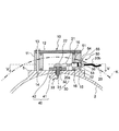
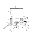
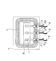
- FIG. 3 is a III-III cross-sectional view of the cover member and the like shown in FIG. It is a figure which shows the state which removed the cover body of the cover member shown in FIG. FIG.
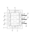
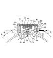
- FIG. 5 is a diagram showing a state where a cover member is cut at a position of a VV line in FIG. 3. It is a figure corresponding to FIG. 2 of the cover member with which the electric motor which concerns on 2nd Embodiment of this invention is equipped. It is a figure corresponding to FIG. 3 of the electric motor which concerns on 2nd Embodiment.
- FIG. 8 is a view corresponding to FIG. 4, showing a state where a cover of the cover member shown in FIG. 7 is removed.
- FIG. 6 is a view corresponding to FIG. 5, showing a state where the cover member is cut at the position of the line IX-IX in FIG. 7.
- FIG. 9 is a view corresponding to FIG. 8, showing a state where the cover member of the modified example shown in FIG. 11 is removed from the motor casing.
- an electric motor 1 As shown in FIG. 1 (a), an electric motor 1 according to the first embodiment is formed of a motor casing 2 made of aluminum alloy and an outer surface of the motor casing 2 so as to project like a bowl, and is attached to a screw mounting hole. And a flange 3 provided with 3a.
- an armature (not shown) that is supplied with electric power and rotates is stored.
- the flange 3 is screwed to the installation location with a bolt 4.
- a cover member 10 made of aluminum alloy protrudes and is attached to the outer surface of the motor casing 2.
- the cover member 10 is attached to the motor casing 2
- the bolt 4 in the screwing location from above, as shown by the two-dot chain line arrow in FIG.
- a state where the cover member 10 is removed from the motor casing 2 as shown by a two-dot chain line arrow in FIG.
- a mounting base 5 is provided on the outer surface of the motor casing 2 so as to protrude.
- the cover member 10 is detachably attached to the mounting base 5 by screwing using bolts 13.
- the mounting base 5 is provided with three exposed conductive portions 30 that are electrically connected to the armature.
- a terminal 21 is provided at one end of the electric wire 20.
- the terminal 21 is electrically connected to the conductive portion 30 by being screwed with a connection screw 22 while being in contact with the conductive portion 30.
- the other end of the electric wire 20 is connected to a power source (not shown).
- the distance D1 is the distance from the center line O of the motor casing 2 to the surface of the conductive portion 30 disposed in contact with the terminal 21, and the distance D2 is the center line of the motor casing 2. This is the distance from O to the screwed portion of the flange 3 (the head of the bolt 4). As can be seen by comparing these distances, the conductive portion 30 is located closer to the center line O side of the motor casing 2 than the screwed portion of the flange 3 (the head of the bolt 4). 3 is a virtual line drawn connecting the centers of the plurality of mounting holes 3a.
- the conductive portion 30 is provided at one end of an electric wire 33 connected to an armature (not shown) in the motor casing 2 and is a cylindrical shape electrically connected to the electric wire 33.
- a conductive cylinder part 31 and a contact plate part 32 formed in a disk shape at one end of the conductive cylinder part 31 are provided.
- the terminal 21 is disposed in contact with the contact plate portion 32.
- a wiring hole 6 is provided in the mounting base 5 of the motor casing 2.
- a conductive cylinder portion 31 of the conductive portion 30 is inserted into the wiring hole 6.
- a seal member 40 made of an insulating member is also inserted into the wiring hole 6.
- a cylindrical insulating cylinder portion 41 that is located on the outer peripheral side of the conductive cylinder portion 31 in the wiring hole 6 and fills a gap between the conductive cylinder portion 31 and the inner wall surface of the wiring hole 6,
- An insulating cylinder portion 41 is provided at one end of the insulating cylinder portion 41 and is formed in a disk shape and is located between the mount 5 and the conductive portion 30. That is, the seal member 40 is electrically insulated from the motor casing 2 made of aluminum alloy and the conductive portion 30 while ensuring the airtightness of the motor casing 2 at the position of the wiring hole 6.
- the cover member 10 includes a cylindrical body 11 and a lid body 12.
- the cylindrical body 11 is screwed with a bolt 13 in a state where one end side in the penetrating direction is in contact with the mounting base 5.
- 14 is a female screw portion into which the bolt 13 is screwed
- 15 is a positioning pin for positioning the cylinder 11 with respect to the mounting base 5.
- the lid body 12 is fastened together with the cylinder body 11 by bolts 13 and fixed to the mounting base 5.
- the cover member 10 is attached to the outer surface of the motor casing 2 while covering the terminal 21 and the conductive portion 30 of the connected electric wire 20. ing.
- a seal member 16 is provided in an annular shape at each of the end of the cylinder 11 on the mounting base 5 side and the end of the cylinder 11 on the lid 12 side.
- the cover member 10 includes electric wire attachment means 50 that secures the airtightness of the cover member 10 and holds the electric wire 20 and positions the terminal 21 of the electric wire 20 so as to contact the conductive portion 30.
- the electric wire attaching means 50 includes an insulating tube 51 that covers an attachment portion of the electric wire 20 with respect to the cylindrical body 11, a wiring hole 52 provided in the cylindrical body 11 and through which the tube 51 is inserted, and an outer peripheral surface of the tube 51. O-ring 53 that is attached to the tube 51 and fills the gap between the inner wall surface of the wiring hole 52 and the outer peripheral surface of the cylindrical body 11 that is provided at the end of the tube 51 opposite to the terminal 21 side.
- the electric wire 20 includes a conductor (not shown) to which the terminal 21 is electrically connected, an inner sheath 20a that covers the outer peripheral surface of the conductor, and an outer sheath 20b that covers the outer peripheral surface of the inner sheath 20a. Are provided.
- the electric motor 1 according to the first embodiment configured as described above is installed as follows.
- the motor casing 2 is in a state in which the cover member 10 (the cylindrical body 11 and the lid body 12) is removed, and the flange 3 is screwed to the installation location in this state. (See FIG. 1 (b)).
- the electric wire 20 is attached to the cylinder 11 of the cover member 10 by the electric wire attachment means 50.
- the seal member 16 is attached to each of the end of the cylindrical body 11 on the mounting base 5 side and the opposite end thereof, and the cylindrical body 11 is positioned on the mounting base 5 by the positioning pins 15. At this time, the terminal 21 of the electric wire 20 is disposed in contact with the contact plate portion 32 of the conductive portion 30.
- the terminal 21 of the electric wire 20 is screwed to the contact plate portion 32 of the conductive portion 30 with the connection screw 22 while holding the cylindrical body 11 in a positioned state (see FIG. 4).
- the lid body 12 is disposed at the end of the cylindrical body 11 opposite to the mounting base 5 side, and the cylindrical body 11 and the lid body 12 are fastened together with the bolts 13 and attached to the mounting base 5. This completes the installation of the electric motor 1 according to the first embodiment.
- the conductive portion 30 is located closer to the center line O side of the motor casing 2 than the screwed portion of the flange 3 (the head of the bolt 4). Thereby, when screwing the flange 3 to an installation location, the conductive portion 30 does not get in the way for the operator.
- the conductive portion 30 that is electrically connected to the armature in the motor casing 2 is provided on the outer surface of the motor casing 2.
- the connection work of the electric wire only connects the terminal 21 of the electric wire 20 connected to the power source outside the electric motor to the conductive portion 30. That is, there is no need to connect the motor-side electric wire connected to the armature in the motor casing to the motor-side connecting portion of the terminal block as in the case of the conventional electric motor described above. Therefore, the labor for installing the electric motor can be reduced.
- the wire attachment means 50 contacts the terminal 21 of the wire 20 with the conductive portion 30. Position so that. Therefore, the cylindrical body 11 of the cover member 10 is attached to the outer surface of the motor casing 2 and the positioning of the terminal 21 of the electric wire 20 with respect to the conductive portion 30 is completed. Also by this, the labor of installation work of the electric motor 1 can be reduced.
- the electric motor according to the second embodiment includes a terminal 60, a conductive portion 70, and a pressing means 80 in place of the terminal 21, the conductive portion 30, and the connection screw 22 in the electric motor according to the first embodiment, and other configurations. Is the same as the electric motor according to the first embodiment.
- the terminal 60 and the contact plate portion 71 of the conductive portion 70 do not have a structure for screwing.
- the electrical connection of the terminal 60 to the conductive portion 70 is realized by the pressing means 80 constantly pressing the terminal 60 against the contact plate portion 71 of the conductive portion 70 in a state where the cover member 10 is attached to the outer surface of the motor casing 2. Has been.
- the pressing means 80 will be specifically described below.
- the pressing means 80 includes an abutting portion 81 positioned with the terminal 60 interposed between the conductive portion 70 in a state where the cover member 10 (the cylindrical body 11 and the lid body 12) is attached to the outer surface of the motor casing 2.
- a coil spring 82 is provided as an elastic portion that constantly presses the contact portion 81 against the terminal 60 by elastic force.
- One end of the coil spring 82 is located on the mounting base 5 side, and the other end opposite to the one end is located on the lid 12 side.
- a contact portion 81 is fixed to one end of the coil spring 82.
- the coil spring 82 is inserted into the spring guide member 83 so that the elastic deformation direction is linear in the axial direction.
- the spring guide member 83 is a metal member and has a bottomed guide hole 84 that is recessed in a direction away from the mount 5.
- a coil spring 82 is inserted into the guide hole 84 from the other end.
- the coil spring 82 is restricted from moving in the radial direction by the inner peripheral surface of the guide hole 84, whereby the abutting portion 81 moves away from or approaches the lid 12 in the direction of elastic deformation of the coil spring 82.
- the axial direction of the coil spring 82 is limited.
- An insulating member 85 is interposed between the spring guide member 83 and the lid body 12.
- the insulating member 85 is formed with a fitting hole 86 that is recessed in a direction away from the mounting base 5, and the spring guide member 83 is fitted into the fitting hole 86 so that it is difficult to remove.
- a fitting frame 87 projects from the surface of the lid 12 on the mounting base 5 side, and an insulating member 85 is fitted into the fitting frame 87 so that it is difficult to remove. That is, the other end of the coil spring 82 is fixed to the lid 12 via the spring guide member 83 and the insulating member 85.
- the electric motor according to the second embodiment configured as described above is installed as follows.
- the motor casing 2 is in a state in which the cover member 10 (the cylindrical body 11 and the lid body 12) is removed, and the flange 3 is screwed to the installation location in this state ( (Refer FIG.1 (b)).
- the electric wire 20 is attached to the cylinder 11 of the cover member 10 by the electric wire attachment means 50.
- the seal member 16 is attached to the end of the cylindrical body 11 on the mounting base 5 side and the end of the lid 12 side, and the cylindrical body 11 is positioned on the mounting base 5 by the positioning pins 15. At this time, the terminal 60 of the electric wire 20 is disposed in contact with the contact plate portion 32 of the conductive portion 70.
- the lid 12 is disposed at the end of the cylinder 11 opposite to the mounting base 5 while holding the cylinder 11 in a positioned state.
- the abutting portion 81 of the pressing means 80 is pressed against the terminal 60 against the elastic force in the extending direction of the coil spring 82, whereby the terminal 60 is pressed against the contact plate portion 32 of the conductive portion 70.
- the conductive portion 70 is closer to the center line O side of the motor casing 2 than the screwed portion of the flange 3 (the head of the bolt 4), as in the electric motor according to the first embodiment. Located in. Thereby, when screwing the flange 3 to an installation location, the conductive portion 70 does not get in the way for the operator.
- the conductive portion 70 electrically connected to the armature in the motor casing 2 is provided on the outer surface of the motor casing 2 as in the electric motor 1 according to the first embodiment. Therefore, the connection work of the electric wire at the time of installing the electric motor 1 only connects the terminal 60 of the electric wire 20 connected to the power source to the conductive portion 70. That is, there is no need to connect the motor-side electric wire connected to the armature in the motor casing to the motor-side connecting portion of the terminal block as in the case of the conventional electric motor described above. Therefore, the labor for installing the electric motor can be reduced.
- the electric wire attachment means 50 positions the terminal 60 of the electric wire 20 so as to contact the conductive portion 70, and presses it.
- the contact portion 81 of the means 80 is located with the terminal sandwiched between the conductive portion 70 and the coil spring 82 (elastic portion) constantly presses the contact portion 81 against the terminal 60 by elastic force. Therefore, the cylindrical body 11 of the cover member 10 can be attached to the outer surface of the motor casing 2 and at the same time the terminal 60 of the electric wire 20 can be positioned with respect to the conductive portion 70, or the lid body 12 of the cover member 10 can be placed on the cylindrical body 11. Simultaneously with the attachment, the electric wire 20 can be connected to the conductive portion 70. Also by this, the labor of installation work of the electric motor 1 can be reduced.
- the terminal 60 is positioned with respect to the conductive portion 70 by utilizing the fact that the electric wire 20 is fixed to the cover member 10 by the electric wire attachment means 50.
- the conductive portion 70 and the contact portion 81 simply press the terminal 60 against the contact plate portion 32 of the conductive portion 70 as shown in FIG.
- the modification shown in FIG. 10 may be used. According to these modified examples, it is possible to realize an electric motor with higher stability of the contact state of the terminal 60 with respect to the conductive portion 70 than the electric motor according to the second embodiment.
- a modification shown in FIG. 10 will be described.
- 91 is a contact plate portion of the conductive portion 70
- 93 is a contact portion.
- the contact plate portion 91 has a concave portion 92 that is recessed in a direction away from the contact portion 93
- the contact portion 93 has a convex portion 94 that protrudes in a direction approaching the contact plate portion 91. That is, in a state where the terminal 60 is in contact with the contact plate portion 91 of the conductive portion 70 in the concave portion 92, that is, in a state where the sliding operation of the terminal 60 with respect to the contact plate portion 91 is restricted in the concave portion 92.
- the convex portion 94 is pressed against the bottom surface of the concave portion 92 of the contact plate portion 91. Thereby, the stability of the contact state of the terminal 60 with respect to the conductive portion 70 is improved.
- reference numeral 100 denotes a contact portion.
- the contact portion 100 has a restriction groove 101 having a triangular cross section on the surface on the conductive portion 70 side. That is, the terminal 60 is located on the contact plate 71 of the conductive portion 70 so as to be fitted in the restriction groove 101 of the contact portion 100, so that the sliding operation with respect to the contact portion plate 71 is suppressed. It is pressed against the contact plate portion 32 by an elastic force. Thereby, the stability of the contact state of the terminal 60 with respect to the conductive portion 70 is improved.
- the cover member 10 includes the cylinder body 11 and the lid body 12, but the cylinder body 11 and the lid as indicated by 110 in FIGS. 11 and 12.
- the cover member integrally formed with the body 12 may be used. Thereby, an electric motor with fewer parts than the electric motor according to the second embodiment can be realized.
- the coil spring 82 is fixed to the lid 12 via the spring guide member 83, the insulating member 85, and the fitting frame 87.
- the lid 12 and the spring guide member 83 are made of metal for ease of securing the strength, and therefore an insulating member 85 is required between the spring guide member 83 and the lid 12.
- the spring guide member 83 is an insulating member having sufficient strength to guide the coil spring 82
- the guide member may be directly fitted into the fitting frame 87 of the lid 12 so that it is difficult to remove. Good.
- a frame that functions as the spring guide member 83 instead of the fitting frame 87 is provided at the position of the fitting frame 87 of the lid 12. May be.
Landscapes
- Engineering & Computer Science (AREA)
- Power Engineering (AREA)
- Motor Or Generator Frames (AREA)
Abstract
Description
第1実施形態に係る電動モータについて図1~図5を用いて説明する。
接触板部32に対して端子21が接触して配置される。
第2実施形態に係る電動モータについて図6~図12を用いて説明する。これら図6~図12に示すもののうち、図1~図5に示したものと同等のものには、図1~図5と同じ符号を使用してある。
2 モータケーシング
3 フランジ
3a 取付孔
4 ボルト
5 取付台
6 配線孔
10 カバー部材
11 筒体
12 蓋体
13 ボルト
14 雌ネジ部
15 位置決めピン
16 シール部材
20 電線
20a 内被
20b 外被
21 端子
22 接続ネジ
30 導電部
31 導電筒部
32 接触板部
33 電線
40 シール部材
41 絶縁筒部
42 絶縁鍔部
50 電線取付手段
51 チューブ
52 配線孔
53 Oリング
54 固定板
55 ネジ
56 雌ネジ部
O 中心線
60 端子
70 導電部
80 押付手段
81 当接部
82 コイルスプリング(弾性部)
83 スプリングガイド部材
84 ガイド穴
85 絶縁部材
86 嵌合穴
87 嵌合枠
91 接触板部
92 凹部
93 当接部
94 凸部
100 当接部
101 規制溝
110 カバー部材
Claims (2)
- 電機子を格納したモータケーシングと、
このモータケーシングの外側面に鍔状に突出して形成され、ネジ留め箇所が複数設けられたフランジと、
前記電機子に電気的に接続され前記モータケーシングの外側面に露出して設けられ、前記フランジのネジ留め箇所よりも前記モータケーシングの中心線側に位置する導電部と、
一端に端子を有しこの端子の位置で前記導電部に電気的に接続され、他端が電源に接続される電線と、
電気的に接続された状態の前記端子と前記導電部を覆って前記モータケーシングの外側面に着脱可能に取り付けられたカバー部材とを備える
ことを特徴とする電動モータ。 - 請求項1に記載の電動モータにおいて、
前記カバー部材は、このカバー部材が前記モータケーシングの外側面に取り付けられた状態において前記カバー部材の気密性を確保して前記電線を保持するとともに前記電線の前記端子を前記導電部に接触するよう位置決めする電線取付手段と、前記カバー部材が前記モータケーシングの外側面に取り付けられた状態において前記導電部に前記電線の前記端子を常時押し付ける押付手段とを備え、
前記押付手段は、前記カバー部材が前記モータケーシングの外側面に取り付けられた状態において前記導電部との間で前記端子を挟んで位置する当接部と、この当接部が一端に固定され他端が前記カバー部材に固定され、前記当接部を弾性力により常時前記端子に押し付ける弾性部とを備える
ことを特徴とする電動モータ。
Priority Applications (4)
| Application Number | Priority Date | Filing Date | Title |
|---|---|---|---|
| EP12771671.0A EP2698904A4 (en) | 2011-04-14 | 2012-04-12 | ELECTRIC MOTOR |
| US14/007,378 US20140300225A1 (en) | 2011-04-14 | 2012-04-12 | Electric Motor |
| CN201280017928.XA CN103460565B (zh) | 2011-04-14 | 2012-04-12 | 电动马达 |
| KR1020137029836A KR20140023972A (ko) | 2011-04-14 | 2012-04-12 | 전동 모터 |
Applications Claiming Priority (2)
| Application Number | Priority Date | Filing Date | Title |
|---|---|---|---|
| JP2011090214A JP5539256B2 (ja) | 2011-04-14 | 2011-04-14 | 電動モータ |
| JP2011-090214 | 2011-04-14 |
Publications (1)
| Publication Number | Publication Date |
|---|---|
| WO2012141253A1 true WO2012141253A1 (ja) | 2012-10-18 |
Family
ID=47009420
Family Applications (1)
| Application Number | Title | Priority Date | Filing Date |
|---|---|---|---|
| PCT/JP2012/060038 Ceased WO2012141253A1 (ja) | 2011-04-14 | 2012-04-12 | 電動モータ |
Country Status (6)
| Country | Link |
|---|---|
| US (1) | US20140300225A1 (ja) |
| EP (1) | EP2698904A4 (ja) |
| JP (1) | JP5539256B2 (ja) |
| KR (1) | KR20140023972A (ja) |
| CN (1) | CN103460565B (ja) |
| WO (1) | WO2012141253A1 (ja) |
Cited By (2)
| Publication number | Priority date | Publication date | Assignee | Title |
|---|---|---|---|---|
| CN104104172A (zh) * | 2013-04-08 | 2014-10-15 | 日本电产三协株式会社 | 马达 |
| JP2015109742A (ja) * | 2013-12-04 | 2015-06-11 | 日産自動車株式会社 | 回転電機の端子接続構造 |
Families Citing this family (4)
| Publication number | Priority date | Publication date | Assignee | Title |
|---|---|---|---|---|
| USD776680S1 (en) | 2015-02-27 | 2017-01-17 | Samsung Electronics Co., Ltd. | Display screen or portion thereof with animated graphical user interface |
| JP6732133B2 (ja) * | 2017-07-27 | 2020-07-29 | 三菱電機株式会社 | 圧縮機及び空気調和機の室外機 |
| CN107438346B (zh) * | 2017-08-02 | 2023-06-30 | 珠海格力电器股份有限公司 | 电气装配结构和逆相保护器 |
| JP7155785B2 (ja) * | 2018-09-14 | 2022-10-19 | 株式会社アイシン | 端子台ユニット |
Citations (4)
| Publication number | Priority date | Publication date | Assignee | Title |
|---|---|---|---|---|
| JPS5897966U (ja) * | 1981-12-23 | 1983-07-04 | 株式会社日立製作所 | 電動ポンプ |
| JPS5997567U (ja) * | 1982-12-22 | 1984-07-02 | 株式会社日立製作所 | 単相電動機用端子箱 |
| JPH0742554A (ja) | 1993-07-30 | 1995-02-10 | Isuzu Ceramics Kenkyusho:Kk | エンジンの燃焼室 |
| JP2002125348A (ja) * | 2000-10-12 | 2002-04-26 | Suzuki Motor Corp | 配線接続装置 |
Family Cites Families (7)
| Publication number | Priority date | Publication date | Assignee | Title |
|---|---|---|---|---|
| JPS59110896A (ja) * | 1982-12-15 | 1984-06-26 | Ebara Corp | 水中モ−タポンプ |
| JPH0742554U (ja) * | 1993-12-27 | 1995-08-04 | 株式会社川本製作所 | ポンプ駆動電動機の端子箱 |
| JP4138696B2 (ja) * | 2004-04-20 | 2008-08-27 | 三菱電機株式会社 | ノックセンサ |
| CN101490929B (zh) * | 2006-07-12 | 2011-08-31 | 丰田自动车株式会社 | 马达组件 |
| US8004125B2 (en) * | 2007-04-19 | 2011-08-23 | Mitsubishi Electric Corporation | Motor, pump, and method of manufacturing the motor |
| DE102008028622B4 (de) * | 2008-06-18 | 2025-05-15 | Sew-Eurodrive Gmbh & Co Kg | Elektromotor |
| DE102008058511A1 (de) * | 2008-11-21 | 2010-05-27 | Kostal Industrie Elektrik Gmbh | Frequenzumrichter zum Steuern eines Elektromotors |
-
2011
- 2011-04-14 JP JP2011090214A patent/JP5539256B2/ja not_active Expired - Fee Related
-
2012
- 2012-04-12 EP EP12771671.0A patent/EP2698904A4/en not_active Withdrawn
- 2012-04-12 CN CN201280017928.XA patent/CN103460565B/zh not_active Expired - Fee Related
- 2012-04-12 KR KR1020137029836A patent/KR20140023972A/ko not_active Withdrawn
- 2012-04-12 WO PCT/JP2012/060038 patent/WO2012141253A1/ja not_active Ceased
- 2012-04-12 US US14/007,378 patent/US20140300225A1/en not_active Abandoned
Patent Citations (4)
| Publication number | Priority date | Publication date | Assignee | Title |
|---|---|---|---|---|
| JPS5897966U (ja) * | 1981-12-23 | 1983-07-04 | 株式会社日立製作所 | 電動ポンプ |
| JPS5997567U (ja) * | 1982-12-22 | 1984-07-02 | 株式会社日立製作所 | 単相電動機用端子箱 |
| JPH0742554A (ja) | 1993-07-30 | 1995-02-10 | Isuzu Ceramics Kenkyusho:Kk | エンジンの燃焼室 |
| JP2002125348A (ja) * | 2000-10-12 | 2002-04-26 | Suzuki Motor Corp | 配線接続装置 |
Non-Patent Citations (1)
| Title |
|---|
| See also references of EP2698904A4 * |
Cited By (2)
| Publication number | Priority date | Publication date | Assignee | Title |
|---|---|---|---|---|
| CN104104172A (zh) * | 2013-04-08 | 2014-10-15 | 日本电产三协株式会社 | 马达 |
| JP2015109742A (ja) * | 2013-12-04 | 2015-06-11 | 日産自動車株式会社 | 回転電機の端子接続構造 |
Also Published As
| Publication number | Publication date |
|---|---|
| JP2012223079A (ja) | 2012-11-12 |
| KR20140023972A (ko) | 2014-02-27 |
| JP5539256B2 (ja) | 2014-07-02 |
| EP2698904A4 (en) | 2016-04-20 |
| EP2698904A1 (en) | 2014-02-19 |
| CN103460565A (zh) | 2013-12-18 |
| CN103460565B (zh) | 2016-01-27 |
| US20140300225A1 (en) | 2014-10-09 |
Similar Documents
| Publication | Publication Date | Title |
|---|---|---|
| JP5539256B2 (ja) | 電動モータ | |
| JP5206480B2 (ja) | コネクタ装置 | |
| JP5194609B2 (ja) | 機器用コネクタ | |
| CN102420368B (zh) | 连接器 | |
| JP5077670B2 (ja) | 機器用コネクタ | |
| JP5399800B2 (ja) | 防水構造 | |
| JP5434612B2 (ja) | 端末接続装置 | |
| JP3909680B2 (ja) | コネクタ構造 | |
| US9570838B2 (en) | Structure of highly waterproof connector for easy conduction between ground pin and body | |
| JP6114135B2 (ja) | 保護カバー構造 | |
| CN104218336A (zh) | 端子板 | |
| JP2013097946A (ja) | インバータとモータ内蔵ドライブトレインとの電気的接続構造 | |
| JP5999448B2 (ja) | シールドコネクタ | |
| JPWO2015060113A1 (ja) | シールドコネクタ | |
| CN104218335B (zh) | 端子板 | |
| JP6854866B1 (ja) | 電力変換装置 | |
| JPH03107356A (ja) | 車両の三相交流発電機の整流装置 | |
| JP2010140873A (ja) | 機器用コネクタの防水構造 | |
| JP7174862B2 (ja) | ステータアセンブリ及びモータ | |
| JP4784360B2 (ja) | 電気接続構造 | |
| JP4313290B2 (ja) | 接続端子 | |
| JP4317483B2 (ja) | 機器用コネクタ | |
| CN211456889U (zh) | 一种电动车轮毂电机用接线盒 | |
| JP5682696B1 (ja) | 電気コネクタの取付構造 | |
| CN118659571A (zh) | 电机端盖、汽车空气悬架电机及电机端盖生产工艺 |
Legal Events
| Date | Code | Title | Description |
|---|---|---|---|
| 121 | Ep: the epo has been informed by wipo that ep was designated in this application |
Ref document number: 12771671 Country of ref document: EP Kind code of ref document: A1 |
|
| WWE | Wipo information: entry into national phase |
Ref document number: 2012771671 Country of ref document: EP |
|
| NENP | Non-entry into the national phase |
Ref country code: DE |
|
| ENP | Entry into the national phase |
Ref document number: 20137029836 Country of ref document: KR Kind code of ref document: A |
|
| WWE | Wipo information: entry into national phase |
Ref document number: 14007378 Country of ref document: US |