WO2012141420A2 - 감마선 검출 장치 및 이를 이용한 감마선 검출 방법 - Google Patents
감마선 검출 장치 및 이를 이용한 감마선 검출 방법 Download PDFInfo
- Publication number
- WO2012141420A2 WO2012141420A2 PCT/KR2012/000809 KR2012000809W WO2012141420A2 WO 2012141420 A2 WO2012141420 A2 WO 2012141420A2 KR 2012000809 W KR2012000809 W KR 2012000809W WO 2012141420 A2 WO2012141420 A2 WO 2012141420A2
- Authority
- WO
- WIPO (PCT)
- Prior art keywords
- radiation detector
- secondary electrons
- gamma ray
- energy
- radiation
- Prior art date
- Legal status (The legal status is an assumption and is not a legal conclusion. Google has not performed a legal analysis and makes no representation as to the accuracy of the status listed.)
- Ceased
Links
Images


Classifications
-
- G—PHYSICS
- G01—MEASURING; TESTING
- G01T—MEASUREMENT OF NUCLEAR OR X-RADIATION
- G01T1/00—Measuring X-radiation, gamma radiation, corpuscular radiation, or cosmic radiation
- G01T1/16—Measuring radiation intensity
- G01T1/20—Measuring radiation intensity with scintillation detectors
- G01T1/2006—Measuring radiation intensity with scintillation detectors using a combination of a scintillator and photodetector which measures the means radiation intensity
-
- A—HUMAN NECESSITIES
- A61—MEDICAL OR VETERINARY SCIENCE; HYGIENE
- A61B—DIAGNOSIS; SURGERY; IDENTIFICATION
- A61B6/00—Apparatus or devices for radiation diagnosis; Apparatus or devices for radiation diagnosis combined with radiation therapy equipment
-
- A—HUMAN NECESSITIES
- A61—MEDICAL OR VETERINARY SCIENCE; HYGIENE
- A61B—DIAGNOSIS; SURGERY; IDENTIFICATION
- A61B6/00—Apparatus or devices for radiation diagnosis; Apparatus or devices for radiation diagnosis combined with radiation therapy equipment
- A61B6/02—Arrangements for diagnosis sequentially in different planes; Stereoscopic radiation diagnosis
- A61B6/03—Computed tomography [CT]
- A61B6/037—Emission tomography
-
- G—PHYSICS
- G01—MEASURING; TESTING
- G01T—MEASUREMENT OF NUCLEAR OR X-RADIATION
- G01T1/00—Measuring X-radiation, gamma radiation, corpuscular radiation, or cosmic radiation
- G01T1/16—Measuring radiation intensity
- G01T1/28—Measuring radiation intensity with secondary-emission detectors
-
- G—PHYSICS
- G01—MEASURING; TESTING
- G01T—MEASUREMENT OF NUCLEAR OR X-RADIATION
- G01T1/00—Measuring X-radiation, gamma radiation, corpuscular radiation, or cosmic radiation
- G01T1/29—Measurement performed on radiation beams, e.g. position or section of the beam; Measurement of spatial distribution of radiation
-
- A—HUMAN NECESSITIES
- A61—MEDICAL OR VETERINARY SCIENCE; HYGIENE
- A61B—DIAGNOSIS; SURGERY; IDENTIFICATION
- A61B6/00—Apparatus or devices for radiation diagnosis; Apparatus or devices for radiation diagnosis combined with radiation therapy equipment
- A61B6/50—Apparatus or devices for radiation diagnosis; Apparatus or devices for radiation diagnosis combined with radiation therapy equipment specially adapted for specific body parts; specially adapted for specific clinical applications
- A61B6/508—Apparatus or devices for radiation diagnosis; Apparatus or devices for radiation diagnosis combined with radiation therapy equipment specially adapted for specific body parts; specially adapted for specific clinical applications for non-human patients
Definitions
- the present invention relates to a gamma ray detection device and a gamma ray detection method using the same, and more particularly, gamma rays emitted from a gamma source or a nuclear reaction traces the locus of secondary electrons generated by a Compton scattering reaction, and thus source position and distribution of gamma rays.
- the present invention relates to a gamma ray detection apparatus for imaging a gamma ray detection method using the same.
- Bragg Peak a unique energy transfer characteristic called Bragg Peak allows the dose to be concentrated at a desired site and the damage to the surrounding normal tissues can be minimized.
- a gamma-ray emission imaging device composed of a focusing device and a position-sensitive radiation detector is used.
- the gamma-ray emitted from the radiation source passes through the focusing device and then reacts with the position-sensitive radiation detector. If so, the data generated at this time are acquired to image the distribution of the radiation source.
- the conventional imaging apparatus of the above method has a limitation in that it can be generally applied only to gamma rays of 1 MeV or less.
- a gamma ray detection device capable of indirectly detecting the position and distribution of a gamma ray source using secondary electrons generated as described above after converting gamma rays into electrons, and a gamma ray detection method using the same To provide.
- the present invention provides a gamma ray detection apparatus and a gamma ray detection method using the same, which can increase the image resolution of a gamma ray source emitting high energy gamma rays and improve measurement efficiency.
- the present invention provides a gamma ray detecting apparatus and a gamma ray detecting method using the same which can obtain the position and distribution of the gamma ray source in a three-dimensional at a fixed position.
- the present invention provides a gamma ray detection apparatus capable of miniaturizing and reducing the weight of an apparatus for acquiring an image of a gamma ray source, and a gamma ray detection method using the same.
- a secondary electron emitter for causing a secondary gamma ray to emit secondary electrons in the direction of the gamma ray by causing a Compton scattering reaction;
- a first radiation detector provided to face the secondary electron emitter with respect to an emission progressing direction of the secondary electrons, and detecting a position and a transfer energy of the secondary electrons;
- a second radiation detector provided to face the first radiation detector with respect to an emission progressing direction of the secondary electrons, and detecting a position and a transfer energy of the secondary electrons passing through the first radiation detector;
- a third radiation detector provided to face the second radiation detector with respect to an emission progressing direction of the secondary electrons, and absorbing the secondary electrons passing through the second radiation detector to detect residual energy of the secondary electrons;
- a co-factor circuit for determining whether the secondary electrons are simultaneously reacted by the first to third radiation detectors.
- the data processor may detect a position of a source of the gamma ray
- the first radiation detector or the second radiation detector detects positions of the plurality of secondary electrons
- the data processor may detect a source of gamma rays from an intersection point of a line connecting the positions of the secondary electrons.
- the secondary electron emitter may be formed of a material of any one of liquefied helium, beryllium or distilled water so that the secondary electrons are emitted from the secondary electron emitter while maintaining a linear trajectory.
- the first radiation detector or the second radiation detector has a low atomic number or high density so as to maintain a linear trajectory while the secondary electrons emitted from the secondary electron emitter pass through the first radiation detector or the second radiation detector. It can be formed of a low material.
- the first radiation detector or the second radiation detector may be formed of a double-sided silicon strip type.
- the interval between the first and second radiation detectors may be greater than the interval between the second and third radiation detectors. That is, the spacing between the first and second radiation detectors should be sufficiently large, and the spacing between the second and third radiation detectors should be minimized so as to efficiently measure secondary electrons passing through the second radiation detector.
- the thickness of the third radiation detector may be greater than the thickness of the first radiation detector or the second radiation detector.
- the third radiation detector is preferably formed thick enough, that is, all the secondary electrons generated in the process of absorbing the secondary electrons inside the third radiation detector to accurately determine the energy of the secondary electrons passing through the second radiation detector; This is because X-rays must absorb themselves.
- the gamma ray detection device may include an energy selector that adds energy of secondary electrons detected by the first to third radiation detectors and determines whether the sum of energy is included in a set reference energy range. It may be determined whether the data detected by the selector is valid data capable of obtaining the position of the gamma ray source as a 3D image.
- the gamma ray detecting method using the gamma ray detecting device (a) causing a compton scattering reaction with the gamma ray incident on the secondary electron emitter, and emitting the secondary electrons in the same direction as the traveling direction of the gamma ray ; (b) detecting the position and the transfer energy of the secondary electron at the time when the secondary electron passes through the first radiation detector; (c) detecting the position and the transfer energy of the secondary electron at the time when the secondary electron passes through the second radiation detector; (d) detecting residual energy of the secondary electrons at the time when the secondary electrons are absorbed by the third radiation detector; (e) detecting data of the secondary electrons simultaneously detected by the first to third radiation detectors using the data processor; (f) detecting a source position of the gamma ray by tracing the trace of the secondary electrons detected by the first and second radiation detectors in reverse; And (g) acquiring, as an image, data included in the reference energy range in which the sum of energie
- the method may include measuring energy Ea2 and energy Eb2 delivered by the secondary electrons.
- the point where the two trajectories intersect each other is called the three-dimensional source position of the gamma ray. You can judge.
- step (e) data of secondary electrons simultaneously detected by the first to third radiation detectors may be selected using a simultaneous counting circuit. This is because, since the first and second radiation detectors use very thin detectors, it is very rare for uncharged particles to react directly with two detectors at the same time. This is because it can be judged.
- the sum of the energy of the secondary electrons detected by the first to third radiation detectors may select data included in the set reference energy range.
- the energy included in each reference energy range in which the energy of the secondary electron 70 delivered to the first radiation detector 130 and the second radiation detector 140 is set may be selected. Since the data included in the reference energy range is selected as described above, the data included in the reference energy can be regarded as a valid response and the rest can be effectively removed.
- the gamma ray detecting apparatus and the gamma ray detecting method according to the present invention since the emission trajectory of the secondary electrons generated in response to the gamma ray is traced back, the position of the gamma ray source is indirectly detected, thereby increasing the detection efficiency. In addition, image resolution for high energy gamma sources can be improved.
- the gamma ray detecting apparatus and the gamma ray detecting method according to the present invention can image the position and distribution of the gamma ray source in a three-dimensional position at a fixed position, and the user's convenience of using the device by miniaturizing and reducing the device for detecting the gamma ray source. It can increase.
- the gamma ray detecting apparatus and the gamma ray detecting method according to the present invention can minimize noise because an energy selector is applied.
- the gamma ray detection device and gamma ray detection method according to the present invention can also be applied to imaging radioisotopes emitting gamma rays having high energy.
- FIG. 1 is a block diagram schematically illustrating an apparatus for detecting gamma rays according to an exemplary embodiment of the present invention.
- FIG. 2 is a diagram schematically illustrating a gamma ray detecting apparatus according to an embodiment of the present invention.
- FIG. 3 is a flowchart illustrating a gamma ray detection method according to an embodiment of the present invention.
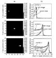
- FIG. 4 is a view showing the results of experiments on the proton beam irregularity using the gamma ray detection apparatus according to an embodiment of the present invention.
- FIG. 1 is a block diagram schematically showing a gamma ray detecting apparatus according to an embodiment of the present invention
- FIG. 2 is a diagram schematically showing a gamma ray detecting apparatus according to an embodiment of the present invention
- FIG. 3 is an embodiment of the present invention.
- 4 is a flowchart illustrating a gamma ray detection method according to an embodiment of the present invention.
- FIG. 4 is a diagram illustrating a result of experiments using a gamma ray detection apparatus according to an embodiment of the present invention.
- the gamma ray detecting apparatus 100 may include various devices capable of detecting the position of the source 50 of the gamma ray 55 and gamma rays detected by each device ( 55 may include a display unit 180 for displaying the position and distribution of the source 50 in the image.
- the gamma ray 55 emitted from the gamma ray source 50 passes through the secondary electron emitter 120.
- the secondary electron emitter 120 is formed of a material that generates secondary electrons 70 by reacting with the incident gamma ray 55, and the gamma ray 55 generated from the source 50 of the gamma ray 55 is Compton scattered. Reaction causes secondary electrons 70 to be generated.
- the secondary electron emitter 120 may be formed of a material having a low atomic number in which a Compton scattering reaction occurs relatively well so that the secondary electron 70 is more efficiently generated by the high energy gamma ray 55.
- the secondary electron emitter 120 may be formed of a material having a low atomic number and a low density so that the generated secondary electrons 70 may be linearly emitted in the secondary electron emitter 120 with little change in the trajectory.
- it may be formed of liquefied helium, beryllium or distilled water, and the like.
- the secondary electron emitter 120 may be replaced with another material that may generate secondary electrons 70 in reaction with the gamma ray 55 in addition to the above-described materials.
- the secondary electron emitter 120 may be replaced with another material that may generate secondary electrons 70 in reaction with the gamma ray 55 in addition to the above-described materials.
- the secondary electron emitter 120 may be replaced with another material that may generate secondary electrons 70 in reaction with the gamma ray 55
- the secondary electrons 70 emitted from the secondary electron emitter 120 are provided to face the secondary electric vehicle emitter 120 with respect to the emission progress direction of the secondary electrons 70, and the position and the transfer energy of the secondary electrons 70. Pass through the first radiation detector 130 to detect.
- the transfer energy is the energy of the secondary electron 70 delivered to the first radiation detector 130.
- the first radiation detector 130 primarily determines the trajectory of the secondary electrons 70 emitted from the secondary electron emitter 120, and has a very thin thickness to minimize the change of the trajectory of the secondary electrons 70. It may be formed of a material having a small atomic number and low density. That is, by forming the first radiation detector 130 with a material having a small atomic number and a low density, the trajectory of the secondary electrons 70 can be maintained as straight as possible during or after passing through the first radiation detector 130. And the change of the linear trajectory can be minimized.
- the second radiation detector 140 may be provided to face the first radiation detector 130 with respect to the emission progress direction of the secondary electrons 70, and the second radiation detector 140 may pass through the first electrons 70 passing through the first radiation detector 130. Detect location and transfer energy.
- the second radiation detector 140 also has a small thickness and small atoms so as to minimize the linear trajectory change while the secondary electrons 70 emitted from the first radiation detector 130 pass through the second radiation detector 140. It can be formed of a material with a low density and number.
- the first and second radiation detectors 130 and 140 may be formed of the same material, but may be formed of different materials according to the conditions of the invention.
- the first radiation detector 130 and the second radiation detector 140 may be formed of a double-sided silicon strip type.
- the secondary electrons 70 emitted from the second radiation detector 140 are absorbed by the third radiation detector 150. That is, the secondary electron 70 passes through both the first radiation detector 130 and the second radiation detector 140 and finally is completely absorbed by the third radiation detector 150 to stop.
- the third radiation detector 150 absorbs all remaining energy of the secondary electrons 70 emitted from the second radiation detector 140, thereby not only stopping the secondary electrons 70 in the third radiation detector 150.
- the residual energy absorbed may be measured and subsequently applied to the sum energy sorter.
- the first radiation detector 130 and the second radiation detector 140 detects the position and the transfer energy of the secondary electron 70, while the third radiation detector 150 is only the residual energy of the secondary electron 70 There is a difference in detection.
- the interval D1 between the first and second radiation detectors 130 and 140 may be larger than the interval D2 between the second and third radiation detectors 140 and 150.
- the position of the secondary electrons 70 detected by the first and second radiation detectors 130 and 140 may be traced back so that the linear trajectory of the secondary electrons 70 may be more accurately determined.
- the distance D1 between the first and second radiation detectors 130 and 140 may be spaced apart by a sufficient distance.
- the second radiation detector 140 and the third radiation detector ( The spacing D2 between 150 is preferably minimized or smaller than the spacing D1 between the first radiation detector 130 and the second radiation detector 140.
- the distance D1 between the first and second radiation detectors 130 and 140 must be sufficiently large, and the secondary electrons passing through the second radiation detector 140 are provided. It is desirable to minimize the distance D2 between the second and third radiation detectors 140 and 150 in order to efficiently measure or detect.
- the thickness T3 of the third radiation detector 150 may be greater than the thicknesses T1 and T2 of the first and second radiation detectors 130 and 140.
- the third radiation detector 150 determines the energy of the secondary electrons 70 emitted from the second radiation detector 140.
- the secondary electron 70 generates another secondary electron and X-rays while being finally completely absorbed in the third radiation detector 150. Therefore, in order to more accurately determine the energy of the secondary electrons 70 emitted from the second radiation detector 140, the thickness T3 of the third radiation detector 150 is sufficiently large so that the inside of the third radiation detector 150 is increased. It is desirable to be able to absorb by itself all the secondary radiations generated while the secondary electrons 70 are being absorbed.
- the thicknesses T1 and T2 of the first and second radiation detectors 130 and 140 are preferably as thin as possible in order to minimize the influence on the trajectory of the secondary electrons 70.
- the thicknesses T1 and T2 of the first and second radiation detectors 130 and 140 may be formed to have the same thickness as each other, but may also be formed to have different thicknesses. .
- the gamma ray detection apparatus 100 is a simultaneous coefficient for determining whether or not the secondary electrons 70 in all of the first to third radiation detectors 130, 140, 150 to track the position of the gamma ray source 50 It may include a data processor 160 having a circuit.
- the data processor 160 acquires data of the secondary electrons 70 that reacted simultaneously by applying a co-coefficient circuit to the first to third radiation detectors 130, 140, and 150 to lower the background or to signal to noise ratio. ) Can be increased.
- the data processor 160 may track the traces of the secondary electrons 70 detected by the first and second radiation detectors 130 and 140 to detect the position of the source 50 of the gamma ray 55. have. That is, the data processor 160 may connect the positions of the plurality of secondary electrons 70 detected by the first and second radiation detectors 130 and 140 with lines, and detect the positions where the lines cross each other. It can be assumed that the intersection of the detected lines is a three-dimensional position of the gamma ray source 50, and a plurality of such lines can be obtained to image the distribution of the gamma ray source 50 in three dimensions.
- the position of the gamma ray source 50 can be shaped in three dimensions. Therefore, the position of the gamma ray source 50 may be detected in three dimensions in a fixed position without moving the gamma ray detecting apparatus 100 according to an exemplary embodiment of the present invention. As a result, the device can be made smaller and lighter, thereby improving user convenience.
- the gamma ray detection apparatus 100 sums the energy of the secondary electrons 70 detected by the first to third radiation detectors (130, 140, 150), the sum of the energy is set reference energy It may further include an energy selector 170 to determine whether it is included in the range.
- the energy selector 170 obtains a sum energy by adding all the energies of the secondary electrons 70 detected by the first to third radiation detectors 130, 140, and 150 in the data processor 160, and the sum energy is previously obtained. It may be determined whether it is included in the set energy region.
- the predetermined energy region or range may be changed according to a condition required by the present invention, which is set as an energy region or range of the gamma ray 55 emitted from the gamma ray source 50 to be imaged by the user.
- the data is determined to be usable data and then used. It can be used to track the location of the source 50 of the gamma ray 55.
- the energy delivered to the three detectors 130 to 150 by the energy selector 170 it is possible to improve the signal-to-noise ratio and lower the background. This is because, in relation to data processing, even if the data satisfying the simultaneous coefficient by the simultaneous coefficient circuit cannot be regarded as a valid response unless the energy delivered to the detector falls within a predetermined energy range.
- the energy selector 170 If the sum energy of the secondary electrons 70 detected by the energy selector 170 is not in the predetermined energy region, all such data may be removed to lower the background and increase the signal-to-noise ratio. By providing such an energy sorter 170, data when the charged particles with different masses, such as protons, can be removed from the effective data.
- a separate and independent energy selector is used for the first and second radiation detectors 130 and 140, and additionally, all the energy delivered to the three radiation detectors 130, 140 and 150 are added together.
- An energy selector 170 may be separately applied to determine whether the sum energy is included in a predetermined energy range or range.
- the above configuration makes it easier to image the distribution of the gamma ray source 50 or the nuclear reaction that emits the high energy gamma ray 55, and detects and detects the position and energy of the secondary electron 70 generated in the secondary electron emitter 120. Since the trace of the secondary electron 70 is traced back to track the gamma source 50, it is possible to indirectly track the location of the gamma source 50 and more accurately track the location of the gamma source 50 with high efficiency. It becomes possible.
- the gamma ray 55 emitted from the gamma ray source 50 is incident on the secondary electron emitter 120, and the secondary electron emitter 120.
- the incident gamma ray may cause a Compton scattering reaction and secondary electrons 70 may be emitted in the same direction as the incident direction of the gamma ray 55 (S310).
- the gamma ray 55 emitted from the gamma ray source 50 preferably uses a high energy gamma ray 55.
- the reason why the high energy gamma ray 55 is preferred is that as the energy of the gamma ray 55 is higher, most of the initial energy of the gamma ray 55 is transferred to the secondary electrons 70, and the secondary energy received by the gamma ray is transferred. This is because the electrons 70 are mostly emitted in the same direction as the traveling direction of the gamma ray 55.
- the maximum transfer energy transmitted to the secondary electrons 70 is 66.2% for 1MeV gamma rays and 97.5% for 10MeV gamma rays.
- the secondary electrons 70 emitted as described above pass through the first radiation detector 130 and the position and the transfer energy of the secondary electrons 70 at the time when the secondary electrons 70 pass through the first radiation detector 130. (S320) and trace the traces of the secondary electrons 70 detected by the first and second radiation detectors (130, 140) in reverse to detect the position of the source 50 of the gamma ray 55 (S360). .
- the position where the plurality of secondary electrons 70 pass through the first radiation detector 130 and the energy transmitted at the time are set to two points, and each of the two points is a position Pa1, Pb1, and the transfer energy at each position is Ea1. , Eb1, it is possible to detect the positions of the plurality of secondary electrons and the transfer energy at each position (S362).
- the gamma ray detection method according to an embodiment of the present invention a case where the position and energy of the secondary electron 70 is obtained for two points is described as an example, but three or more points are set and the position at each point. And it is natural that the transmission energy can be detected.
- the secondary electrons 70 passing through the first radiation detector 130 pass through the second radiation detector 140, and the position and the transfer energy of the secondary electrons 70 at the time of passing through the second radiation detector 140. It may be detected (S330).
- the plurality of positions where the secondary electron 70 passes through the second radiation detector 140 are Pa2 and Pb2. If the transfer energy at each position is Ea2 or Eb2, the positions of the plurality of secondary electrons and the transfer energy at each position can be detected, respectively (S363).
- the secondary electrons 70 that detect the positions Pa2, Pb2 and the energy Ea2, Eb2 and pass through the second radiation detector 140 are completely absorbed by the third radiation detector 150, thereby remaining of the secondary electrons 70. Energy may be detected (S340).
- the position Pa1 and the position Pa2 of the secondary electrons 70 measured by the first and second radiation detectors 130 and 140, respectively, are connected by a trajectory or line, and the position Pb1 and the position Pb2 are connected by a trajectory or line. . It traces the points intersected with each other by retro-projecting the connected traces (S366), and traces the traces of the secondary electrons 70 in reverse to determine that the gamma ray source 50 is located at the points where the lines intersect (S368). ).
- the energy of the secondary electrons 70 delivered to the first radiation detector 130 and the second radiation detector 140 is included in each of the preset reference energy ranges, and the secondary energy included in the reference energy ranges. Only the data of the former 70 may be selected.
- a simultaneous counting circuit is applied to the three radiation detectors to record only the data in which all three detectors react at almost the same time.
- the first and second radiation detectors 130 and 140 use very thin detectors, it is very rare for uncharged particles to directly react with two detectors at the same time. It is because it can be judged that it is based on a transfer.
- the sum energy obtained by adding up the energy detected by the first to third radiation detectors 130, 140, and 150 is applied to the energy selector 170.
- the energy selector 170 is regarded as a valid response only if the data is satisfied and recorded in the data processor 160 within the energy range set by the user, and removes all others. This can effectively eliminate the case where other charged particles react.
- FIG. 4 shows a gamma ray detecting apparatus and a detection method according to an exemplary embodiment of the present invention, wherein the proton beam is positioned within the water phantom while irradiating a proton beam having therapeutic energy to the water phantom.
- Experimental pictures and graphs are shown. That is, the protons react with the water phantom to generate immediate gamma rays, and the distribution of the instantaneous gamma rays is imaged using the tracking of the secondary electrons, the co-factor, the energy selector, and the linear reverse projection technique.
- the energy of the proton beam used at this time is 80, 150, 200 MeV.
- the experiment was performed by varying the size of the water phantom for each energy.
- the water phantom may serve as the secondary electron emitter 120.
- the size of the water phantom is 2 ⁇ 2 ⁇ 30 cm 3 (80 MeV proton beam), 3 ⁇ 3 ⁇ 30 cm 3 (150 MeV proton beam), 4 ⁇ 4 ⁇ 30 cm 3 (200 MeV proton) for each proton beam. Beam).
- the first photo and graph above are 80 MeV proton beams
- the third photo and graph are 200 MeV proton beams.
- the photograph on the left side (a) is an image of an instantaneous gamma ray distribution obtained by using a gamma ray detecting apparatus and a detection method according to an embodiment of the present invention
- the photograph on the right side (b) shows a central axis of the image.
- the resulting pixel values see GEV image
- the instantaneous gamma-ray distribution in the water phantom see prompt ⁇
- the dose distribution of the protons see proton dose
- the graph labeled "prompt ⁇ " in FIG. 4 (b) shows the distribution of instantaneous gamma rays 55 generated by the proton beam
- the graph labeled "GEV image” shows the gamma ray detection apparatus 100 of the present invention.
- the pixel values of the image obtained by the method are the same.
- the distribution of the immediate gamma rays 55 and the data obtained by the gamma ray detecting apparatus 100 and the method of the present invention coincide with each other very accurately with an error within 1 mm. This will allow accurate inference of the proton beam in real time during treatment or experiments using the proton beam.
- the gamma ray detection apparatus 100 and the gamma ray detection method using the same according to an embodiment of the present invention described above are for nuclear medicine and molecular imaging for medical purposes, imaging apparatus for small animals, brain science, hydraulics using space tracers, and space physics. It can be applied to a variety of fields, such as when using a high energy gamma source can obtain a better image. In particular, it can be used in the proton treatment facility to determine the location and location of the proton beam in real time during treatment, or can be applied to the space gamma ray measurement and imaging device for astrophysics, such as pulsar or supernova debris research.
- the present invention can be applied to the medical field or the space gamma ray imaging field.
Landscapes
- Health & Medical Sciences (AREA)
- Life Sciences & Earth Sciences (AREA)
- High Energy & Nuclear Physics (AREA)
- Molecular Biology (AREA)
- Physics & Mathematics (AREA)
- Medical Informatics (AREA)
- Engineering & Computer Science (AREA)
- General Physics & Mathematics (AREA)
- Spectroscopy & Molecular Physics (AREA)
- Nuclear Medicine, Radiotherapy & Molecular Imaging (AREA)
- Surgery (AREA)
- Optics & Photonics (AREA)
- Pathology (AREA)
- Radiology & Medical Imaging (AREA)
- Biomedical Technology (AREA)
- Heart & Thoracic Surgery (AREA)
- Biophysics (AREA)
- Animal Behavior & Ethology (AREA)
- General Health & Medical Sciences (AREA)
- Public Health (AREA)
- Veterinary Medicine (AREA)
- Measurement Of Radiation (AREA)
- Nuclear Medicine (AREA)
Abstract
입사된 감마선과 컴프턴 산란 반응을 일으켜 상기 감마선의 진행 방향으로 이차 전자를 발생시키는 이차 전자 방출기, 상기 이차 전자의 방출 진행 방향에 대향되고, 상기 이차 전자의 위치 및 전달에너지를 검출하는 제1 방사선 검출기, 상기 이차 전자의 방출 진행 방향 및 상기 제1 방사선 검출기에 대향되며, 상기 제1 방사선 검출기를 통과한 상기 이차 전자의 위치 및 전달에너지를 검출하는 제2 방사선 검출기, 상기 이차 전자의 방출 진행 방향 및 상기 제2 방사선 검출기에 대향되고, 상기 제2 방사선 검출기를 통과한 상기 이차 전자를 흡수하여 상기 이차 전자의 잔여에너지를 검출하는 제3 방사선 검출기, 및 상기 제1 내지 제3 방사선 검출기에서 상기 이차 전자의 동시 반응여부를 판단하는 동시계수회로를 구비한 데이터 처리기를 통해 상기 제1 및 제2 방사선 검출기에서 검출된 상기 이차 전자의 궤적을 역으로 추적하여 상기 감마선의 선원의 위치를 검출하는 감마선 검출 장치 및 감마선 검출 방법이 개시된다.
Description
본 발명은 감마선 검출 장치 및 이를 이용한 감마선 검출 방법에 관한 것으로서, 보다 자세하게는 감마선원 또는 핵반응으로부터 방출된 감마선이 컴프턴 산란 반응을 하여 발생된 이차 전자의 궤적을 역으로 추적하여 감마선의 선원 위치 및 분포를 영상화하는 감마선 검출 장치 및 이를 이용한 감마선 검출 방법에 관한 것이다.
일반적으로 방사선을 이용한 암 치료에 있어서 암 조직에만 국한적으로 방사선 에너지를 전달하여 암 세포를 궤사시키고 주변의 정상 조직에는 피해가 가지 않도록 하는 것이 중요하다. 종래의 방사선 치료는 광자선 또는 전자선을 이용하기 때문에 암 조직에 제한적으로 선량을 가하는 것에 어려움이 있었다.
한편, 양성자를 이용하여 암 치료를 하는 경우에는, 브래그 피크(Bragg Peak)라는 독특한 에너지 전달 특성으로 인해 원하는 부위에 선량을 집중시킬 수 있고 주변의 정상조직의 피해는 최소화할 수 있게 되었다.
하지만, 현재까지 치료 중에 실시간으로 환자 체내에서의 브래그 피크 위치를 정확하게 결정하는 기술은 마련되어 있지 않으며, 이로 인하여 양성자와 타겟 물질과의 반응에 의해 발생되는 즉발 감마선(prompt gamma-ray)의 분포를 통해 브래그 피크의 위치를 유추하는 기술이 각광받고 있다.
상기의 브래그 피크의 위치를 유추하기 위하여 집속 장치 및 위치 민감형 방사선 검출기로 구성된 감마선 방출 영상 장치를 이용하는데, 이는 방사선 선원에서 방출된 감마선이 집속 장치를 통과한 후 위치 민감형 방사선 검출기에서 반응을 일으키면 이 때 발생한 데이터를 획득하여 방사선 선원의 분포를 영상화한다.
그러나, 이러한 기존의 감마선 방출 영상 장치는 여러 가지 문제점들을 가지고 있다. 기존의 감마선 방출 영상 장치는 집속 장치에 의해서 대부분의 감마선이 제거되기 때문에 높은 영상 감도를 획득하기 어렵다. 또한, 감마선은 투과성이 높고 반응 확률이 낮기 때문에 감마선을 직접 검출하는 경우에는 높은 영상 감도를 기대하기 어렵다. 종래의 감마선 방출 영상 장치는 영상 해상도 및 영상 감도가 집속 장치의 구조에 의존하게 되며 서로 상충적인 특징을 갖기 때문에 독립적으로 영상 해상도 또는 영상 감도를 향상시킬 수 없는 제한이 있다.
뿐만 아니라 감마선의 에너지가 높아지면 집속 장치의 성능이 급격하게 저하되면서 영상 해상도가 저하되는 문제가 있다. 이로 인해 상기 방식의 종래 영상장치는 대체적으로 1MeV 이하의 감마선에 대해서만 적용할 수 있다는 한계가 있다.
또한, 감마선이 방출되는 선원에 대한 영상을 3차원으로 획득하기 위해서는 감마선을 계측하는 계측 시스템을 원형으로 배치하거나 회전을 시키면서 대상체를 스캔하여야 하기 때문에 장치를 소형화하는데 한계가 있고 제작 비용도 고가인 문제가 있다.
본 발명은 감마선의 선원을 검출하는데 있어서, 감마선을 일차적으로 전자로 변환시킨 후 이와 같이 발생된 이차 전자를 이용하여 간접적으로 감마선원의 위치와 분포를 검출할 수 있는 감마선 검출 장치 및 이를 이용한 감마선 검출 방법을 제공한다.
본 발명은 고에너지 감마선을 방출하는 감마선원에 대한 영상 해상도를 높일 수 있고 측정 효율을 향상시킬 수 있는 감마선 검출 장치 및 이를 이용한 감마선 검출 방법을 제공한다.
본 발명은 고정된 위치에서 감마선원의 위치 및 분포를 3차원적으로 획득할 수 있는 감마선 검출 장치 및 이를 이용한 감마선 검출 방법을 제공한다.
본 발명은 감마선원의 영상을 획득하기 위한 장치의 소형화 및 경량화가 가능한 감마선 검출 장치 및 이를 이용한 감마선 검출 방법을 제공한다.
상기한 과제를 달성하기 위한 본 발명의 일 실시예에 따른 감마선 검출 장치는, 입사된 감마선과 컴프턴 산란 반응을 일으켜 상기 감마선의 진행 방향으로 이차 전자를 방출시키는 이차 전자 방출기; 상기 이차 전자의 방출 진행 방향에 대해 상기 이차 전자 방출기와 대향되도록 구비되고, 상기 이차 전자의 위치 및 전달에너지를 검출하는 제1 방사선 검출기; 상기 이차 전자의 방출 진행 방향에 대해 상기 제1 방사선 검출기와 대향되도록 구비되고, 상기 제1 방사선 검출기를 통과한 상기 이차 전자의 위치 및 전달에너지를 검출하는 제2 방사선 검출기; 상기 이차 전자의 방출 진행 방향에 대해 상기 제2 방사선 검출기와 대향되도록 구비되고, 상기 제2 방사선 검출기를 통과한 상기 이차 전자를 흡수하여 상기 이차 전자의 잔여 에너지를 검출하는 제3 방사선 검출기; 및 상기 제1 내지 제3 방사선 검출기에서 상기 이차 전자의 동시 반응여부를 판단하는 동시계수회로를 구비한 데이터 처리기; 를 포함하고, 상기 데이터 처리기는, 상기 제1 및 제2 방사선 검출기에서 검출된 상기 이차 전자의 궤적을 역으로 추적하여 상기 감마선의 선원의 위치를 검출할 수 있다.
상기 제1 방사선 검출기 또는 상기 제2 방사선 검출기는 복수의 이차 전자의 위치를 검출하고, 상기 데이터 처리기는 이차 전자의 위치를 연결한 선의 교점으로부터 감마선의 선원을 검출할 수 있다.
상기 이차 전자 방출기는 상기 이차 전자가 직선 궤적을 유지하며 상기 이차 전자 방출기에서 방출되도록 액화 헬륨, 베릴륨 또는 증류수 중 어느 하나의 물질로 형성될 수 있다.
상기 제1 방사선 검출기 또는 상기 제2 방사선 검출기는 상기 이차 전자 방출기에서 방출된 상기 이차 전자가 상기 제1 방사선 검출기 또는 상기 제2 방사선 검출기를 통과하는 동안 직선 궤적을 유지하도록 원자번호가 작거나 밀도가 낮은 물질로 형성될 수 있다.
상기 제1 방사선 검출기 또는 상기 제2 방사선 검출기는 양면 실리콘 스트립 타입으로 형성될 수 있다.
상기 제1 및 제2 방사선 검출기의 간격은 상기 제2 및 제3 방사선 검출기 간격보다 크게 형성될 수 있다. 즉, 제1 및 제2 방사선 검출기 사이의 간격은 충분히 커야 하고, 제2 방사선 검출기를 통과한 이차 전자를 효율적으로 측정할 수 있도록 제2 및 제3 방사선 검출기 사이의 간격은 최소로 하는 것이 바람직하다
상기 제3 방사선 검출기의 두께는 상기 제1 방사선 검출기 또는 상기 제2 방사선 검출기의 두께보다 크게 형성될 수 있다. 제3 방사선 검출기는 충분히 두껍게 형성되는 것이 바람직한데, 이는 제2 방사선 검출기를 통과해서 나오는 이차 전자의 에너지를 정확하게 결정하기 위하여 제3 방사선 검출기 내부에서 이차 전자가 흡수되는 과정에서 발생되는 모든 이차 전자 및 엑스선을 자체적으로 흡수할 수 있어야 하기 때문이다.
상기 감마선 검출 장치는 상기 제1 내지 제3 방사선 검출기에서 검출된 이차 전자의 에너지를 합하고, 합한 에너지가 설정된 기준 에너지 범위에 포함되는지 여부를 판단하는 에너지 선별기를 포함할 수 있다. 상기 선별기에 의하여 검출된 데이터가 감마선원의 위치를 3차원 영상으로 획득할 수 있는 유효한 데이터인지 여부를 판단할 수 있다.
한편, 상기 감마선 검출 장치를 이용한 감마선 검출 방법에 있어서, (a) 상기 이차 전자 방출기에 입사된 상기 감마선과 컴프턴 산란 반응을 일으키고, 상기 감마선의 진행 방향과 동일한 방향으로 상기 이차 전자를 방출시키는 단계; (b) 상기 이차 전자가 상기 제1 방사선 검출기를 통과하는 시점의 상기 이차 전자의 위치 및 전달에너지를 검출하는 단계; (c) 상기 이차 전자가 상기 제2 방사선 검출기를 통과하는 시점의 상기 이차 전자의 위치 및 전달에너지를 검출하는 단계; (d) 상기 이차 전자가 상기 제3 방사선 검출기에 흡수되는 시점의 상기 이차 전자의 잔여에너지를 검출하는 단계; (e) 상기 데이터 처리기를 이용하여 상기 제1 내지 제3 방사선 검출기에서 동시에 검출된 상기 이차 전자의 데이터를 검출하는 단계; (f) 상기 제1 및 제2 방사선 검출기에서 검출된 상기 이차 전자의 궤적을 역으로 추적하여 상기 감마선의 선원 위치를 검출하는 단계; 및 (g) 상기 제1 내지 제3 방사선 검출기에서 검출된 상기 이차 전자의 에너지 합이 설정된 기준 에너지 범위에 포함되는 데이터를 영상으로 획득하는 단계;를 포함할 수 있다.
상기 (b) 단계는 복수의 상기 이차 전자가 상기 제1 방사선 검출기를 통과하는 위치 Pa1, 위치 Pb1 및 상기 위치 Pa1, 위치 Pb1를 통과하는 당시의 상기 이차 전자(70)가 전달한 에너지 Ea1, 에너지 Eb1를 측정하는 단계를 포함하며, 상기 (c) 단계는 상기 제1 방사선 검출기를 통과한 상기 이차 전자가 상기 제2 방사선 검출기를 통과하는 위치 Pa2, 위치 Pb2 및 상기 위치 Pa2, Pb2를 통과하는 당시의 상기 이차 전자가 전달한 에너지 Ea2, 에너지 Eb2를 측정하는 단계를 포함할 수 있다.
상기 (f) 단계에서 측정된 위치 Pa1 및 위치 Pa2를 연결한 궤적과 위치 Pb1 및 위치 Pb2를 연결한 궤적을 역 투사하여, 2개의 궤적이 서로 교차된 지점을 상기 감마선의 3차원적 선원 위치라고 판단할 수 있다.
상기 (e) 단계는, 동시계수회로를 이용하여 상기 제1 내지 제3 방사선 검출기에서 동시에 검출된 이차 전자의 데이터를 선택할 수 있다. 이는, 제1 및 제2 방사선 검출기는 매우 얇은 검출기를 사용하기 때문에 비하전입자가 동시에 두 개의 검출기와 동시에 직접 반응하는 경우는 매우 드물 것이고, 이와 동시에 동시계수를 만족하는 경우는 대부분이 하접입자에 의한 것이라고 판단할 수 있기 때문이다.
상기 (e) 단계는, 제1 내지 제3 방사선 검출기에서 검출된 상기 이차 전자의 에너지 합이 설정된 기준 에너지 범위에 포함되는 데이터를 선택할 수 있다.
상기 (e) 단계는, 상기 제1 방사선 검출기(130) 및 제2 방사선 검출기(140)에 전달된 상기 이차 전자(70)의 에너지가 설정된 각각의 기준 에너지 범위에 포함되는 데이터를 선택할 수 있다. 상기와 같이 기준 에너지 범위에 포함되는 데이터를 선택하기 때문에 기준 에너지에 포함되는 데이터는 유효한 반응이라고 간주하고 나머지는 효과적으로 제거할 수 있다.
이상 설명한 바와 같이, 본 발명에 따른 감마선 검출 장치 및 감마선 검출 방법에 있어서, 감마선과 반응하여 발생된 이차 전자의 방출 궤적을 역으로 추적하여 감마선원의 위치를 간접적으로 검출하기 때문에 검출 효율을 높일 수 있고, 고에너지 감마선원에 대한 영상 해상도를 향상시킬 수 있다.
본 발명에 따른 감마선 검출 장치 및 감마선 검출 방법은 고정된 위치에서 3차원적으로 감마선원의 위치 및 분포를 영상화할 수 있고, 감마선원을 검출하기 위한 장치를 소형화 및 경량화하여 장치를 사용하는 사용자의 편의를 높일 수 있다.
본 발명에 따른 감마선 검출 장치 및 감마선 검출 방법은 에너지 선별기를 적용하기 때문에 노이즈를 최소화할 수 있다.
본 발명에 따른 감마선 검출 장치 및 감마선 검출방법은 고에너지를 가지는 감마선을 방출하는 방사성 동위원소의 영상화에 적용할 수도 있다.
도 1은 본 발명의 일 실시예에 따른 감마선 검출 장치를 개략적으로 도시한 블록도이다.
도 2는 본 발명의 일 실시예의 감마선 검출 장치를 개략적으로 도시한 도면이다.
도 3은 본 발명의 일 실시예에 따른 감마선 검출 방법을 설명하는 순서도이다.
도 4는 본 발명의 일 실시예에 따른 감마선 검출 장치를 이용하여 양성자 빔의 비정을 실험한 결과를 보여주는 도면이다.
이하에서, 본 발명에 따른 실시예들을 첨부된 도면을 참조하여 상세하게 설명한다. 그러나 본 발명이 실시예들에 의해 제한되거나 한정되는 것은 아니다. 각 도면에 제시된 동일한 참조 부호는 동일한 부재를 나타낸다.
도 1은 본 발명의 일 실시예에 따른 감마선 검출 장치를 개략적으로 도시한 블록도, 도 2는 본 발명의 일 실시예의 감마선 검출 장치를 개략적으로 도시한 도면, 도 3은 본 발명의 일 실시예에 따른 감마선 검출 방법을 설명하는 순서도, 도 4는 본 발명의 일 실시예에 따른 감마선 검출 장치를 이용하여 양성자 빔의 비정을 실험한 결과를 보여주는 도면이다.
도 1 및 도 2를 참조하면, 본 발명의 일 실시예에 따른 감마선 검출 장치(100)는 감마선(55)의 선원(50)의 위치를 검출할 수 있는 각종 장비와 각 장비에서 검출되는 감마선(55)의 선원(50)의 위치와 분포를 영상으로 디스플레이하는 디스플레이기(180)를 포함할 수 있다.
상기 감마선(55)의 선원(50)의 위치를 검출할 수 있는 각종 장비에 대해 보다 자세하게 살펴보면, 감마선원(50)에서 방출된 감마선(55)은 이차 전자 방출기(120)를 통과한다. 상기 이차 전자 방출기(120)는 입사된 감마선(55)과 반응하여 이차 전자(70)를 발생시키는 물질로 형성되며, 감마선(55)의 선원(50)에서 발생된 감마선(55)이 컴프턴 산란 반응을 일으켜 이차 전자(70)가 발생된다.
상기 이차 전자 방출기(120)는 고 에너지의 감마선(55)에 의해 이차 전자(70)가 보다 효율적으로 발생되도록 컴프턴 산란 반응이 상대적으로 잘 일어나는 원자 번호가 낮은 물질로 형성될 수 있다. 또한, 발생된 이차 전자(70)가 이차 전자 방출기(120) 내에서 궤적의 변화가 거의 없이 직선적으로 방출될 수 있도록 이차 전자 방출기(120)는 원자번호가 작고 밀도가 낮은 물질로 형성될 수 있다. 예시적으로 액화 헬륨, 베릴륨 또는 증류수 등으로 형성될 수 있으며, 이차 전자 방출기(120)는 상기 제시된 물질 이외에 감마선(55)과의 반응에서 이차 전자(70)가 발생할 수 있는 다른 물질로 대체될 수 있음은 물론이다.
한편, 이차 전자 방출기(120)에서 방출된 이차 전자(70)는 이차 전자(70)의 방출 진행 방향에 대해 이차 전차 방출기(120)와 대향되도록 구비되고, 이차 전자(70)의 위치 및 전달에너지를 검출하는 제1 방사선 검출기(130)를 통과한다. 여기서, 전달에너지는 제1 방사선 검출기(130)에 전달된 이차 전자(70)의 에너지이다.
상기 제1 방사선 검출기(130)는 이차 전자 방출기(120)에서 방출된 이차 전자(70)의 궤적을 1차적으로 결정하게 되며, 이차 전자(70)의 궤적 변화를 최소화하기 위하여 매우 얇은 두께를 가지며 작은 원자번호와 낮은 밀도를 가지는 물질로 형성될 수 있다. 즉, 작은 원자번호와 낮은 밀도를 가지는 물질로 제1 방사선 검출기(130)를 형성함으로써 제1 방사선 검출기(130)를 통과하는 동안 또는 통과한 후 이차 전자(70)의 궤적이 최대한 직선을 유지할 수 있고 직선 궤적의 변화를 최소화할 수 있다.
한편, 제1 방사선 검출기(130)를 통과한 이차 전자(70)는 제2 방사선 검출기(140)를 통과한다. 제2 방사선 검출기(140)는 이차 전자(70)의 방출 진행 방향에 대해 제1 방사선 검출기(130)에 대향되도록 구비될 수 있으며, 제1 방사선 검출기(130)를 통과한 이차 전자(70)의 위치 및 전달에너지를 검출한다.
상기 제2 방사선 검출기(140)도 제1 방사선 검출기(130)에서 방출된 이차 전자(70)가 제2 방사선 검출기(140)를 통과하는 동안 직선 궤적 변화를 최소화할 수 있도록 얇은 두께를 가지며 작은 원자번호와 낮은 밀도를 가지는 물질로 형성될 수 있다. 제1 및 제2 방사선 검출기(130, 140)는 동일한 물질로 형성될 수 있지만, 발명의 조건에 따라서 서로 다른 물질로 형성될 수도 있다. 예를 들어, 제1 방사선 검출기(130) 및 제2 방사선 검출기(140)는 양면 실리콘 스트립 타입으로 형성될 수 있다.
상기 제2 방사선 검출기(140)에서 방출된 이차 전자(70)는 제3 방사선 검출기(150)에서 흡수된다. 즉, 이차 전자(70)는 제1 방사선 검출기(130)와 제2 방사선 검출기(140)를 모두 통과한 후 최종적으로 제3 방사선 검출기(150)에서 완전히 흡수되어 멈추게 된다. 제3 방사선 검출기(150)는 제2 방사선 검출기(140)에서 방출된 이차 전자(70)의 잔여에너지를 모두 흡수함으로써, 이차 전자(70)를 제3 방사선 검출기(150) 내에서 정지시킬 뿐 아니라 흡수된 잔여에너지를 측정하여 추후 합 에너지선별기를 적용할 수도 있다.
여기서, 제1 방사선 검출기(130) 및 제2 방사선 검출기(140)는 이차 전자(70)의 위치 및 전달에너지를 검출하는 반면, 제3 방사선 검출기(150)는 이차 전자(70)의 잔여에너지만을 검출하는 차이가 있다.
이때, 제1 및 제2 방사선 검출기(130, 140) 사이의 간격(D1)은 제2 및 제3 방사선 검출기(140,150) 사이의 간격(D2)보다 크게 형성되는 것이 바람직하다. 도 2에 도시된 바와 같이, 제1 및 제2 방사선 검출기(130, 140)에서 검출된 이차 전자(70)의 위치를 역으로 추적하여 이차 전자(70)의 직선적인 궤적을 보다 정확하게 결정할 수 있도록 상기 제1 및 제2 방사선 검출기(130, 140)의 간격(D1)은 충분한 거리만큼 이격되는 것이 바람직하다.
이에 반해, 제2 방사선 검출기(140)를 통과한 이차 전자(70)가 제3 방사선 검출기(150)로 모두 입사되어 완전히 흡수될 수 있도록 하기 위해서 제2 방사선 검출기(140)와 제3 방사선 검출기(150) 사이의 간격(D2)은 최소화하거나, 제1 방사선 검출기(130)와 제2 방사선 검출기(140) 사이의 간격(D1) 보다 작게 하는 것이 바람직하다. 이와 같이, 이차 전자(70)의 직선 궤적을 보다 정확하게 측정하기 위하여 제1 및 제2 방사선 검출기(130,140) 사이의 간격(D1)은 충분히 커야 하며, 제2 방사선 검출기(140)를 통과하는 이차 전자를 효율적으로 측정하거나 검출하기 위하여 제2 및 제3 방사선 검출기(140,150) 사이의 간격(D2)은 최소화하는 것이 바람직하다.
또한, 제3 방사선 검출기(150)의 두께(T3)는 제1 및 제2 방사선 검출기(130, 140)의 두께(T1, T2) 보다 크게 형성될 수 있다. 앞서 설명한 바와 같이 제3 방사선 검출기(150)는 제2 방사선 검출기(140)에서 방출된 이차 전자(70)의 에너지를 결정하는 역할을 한다. 이차 전자(70)는 제3 방사선 검출기(150) 내에서 최종적으로 완전히 흡수되는 동안 또 다른 이차 전자 및 엑스선(X-ray)을 발생시키게 된다. 따라서, 제2 방사선 검출기(140)에서 방출된 이차 전자(70)의 에너지를 보다 정확하게 결정하기 위해서 제3 방사선 검출기(150)의 두께(T3)를 충분히 크게 하여 제3 방사선 검출기(150) 내부에서 이차 전자(70)가 흡수되는 동안 발생되는 모든 이차 방사선들을 자체적으로 흡수할 수 있도록 하는 것이 바람직하다.
제1 및 제2 방사선 검출기(130,140)의 두께(T1, T2)는 이차 전자(70)의 궤적에 미치는 영향을 최소화하기 위해 가급적 얇게 형성하는 것이 바람직하다. 이때, 제1 및 제2 방사선 검출기(130, 140)의 두께(T1, T2)는 본 발명의 일 실시예와 같이 서로 동일한 두께로 형성될 수 있지만, 서로 다른 두께로 형성될 수도 있음은 물론이다.
한편, 감마선 검출 장치(100)는 감마선원(50)의 위치를 추적하기 위하여 상기 제1 내지 제3 방사선 검출기(130, 140, 150) 모두에서 이차 전자(70)가 반응하였는지 여부를 판단하는 동시계수회로를 구비하는 데이터 처리기(160)를 포함할 수 있다.
상기 데이터 처리기(160)는 제1 내지 제3 방사선 검출기(130,140,150)에 동시계수회로를 적용하여 동시에 반응이 일어난 이차 전자(70)의 데이터를 획득하여 백그라운드를 낮추거나 신호 대 잡음비(Signal to Noise Ratio)를 높일 수 있다.
또한, 데이터 처리기(160)는 제1 및 제2 방사선 검출기(130, 140)에서 검출된 이차 전자(70)의 궤적을 역으로 추적하여 감마선(55)의 선원(50)의 위치를 검출할 수 있다. 즉, 데이터 처리기(160)는 제1 및 제2 방사선 검출기(130, 140)에서 검출된 복수의 이차 전자(70)의 위치를 선으로 연결하고, 각 선이 교차하는 위치를 검출할 수 있다. 검출된 선의 교점이 감마선원(50)의 3차원적 위치라고 가정할 수 있으며, 이러한 선들을 다수 얻어서 감마선원(50)의 분포를 3차원적으로 영상화할 수 있다. 다시 말해 복수의 이차 전자(70)의 궤적을 역투사하면 감마선원(50)의 위치를 3차원적으로 형상화할 수 있다. 이로 인하여 본 발명의 일 실시예에 따른 감마선 검출 장치(100)를 이동할 필요 없이 고정된 자리에서 감마선원(50)의 위치를 3차원적으로 검출할 수 있다. 이로 인하여 장치를 소형화, 경량화하여 사용자의 편의성을 향상시킬 수 있다.
한편, 본 발명의 일 실시예에 따른 감마선 검출 장치(100)는 제1 내지 제3 방사선 검출기(130, 140, 150)에서 검출된 이차 전자(70)의 에너지를 합하고, 합한 에너지가 설정된 기준 에너지 범위에 포함되는지 여부를 판단하는 에너지 선별기(170)를 더 포함할 수 있다.
상기 에너지 선별기(170)는 데이터 처리기(160)에서 제1 내지 제3 방사선 검출기(130, 140, 150)에서 검출된 이차 전자(70)의 에너지를 모두 합쳐 합 에너지를 구하고, 구해진 합 에너지가 미리 설정된 에너지 영역에 포함되는지 판단할 수 있다. 상기 미리 설정된 에너지 영역 내지 범위란 사용자가 영상화하고자 하는 감마선원(50)에서 방출된 감마선(55)의 에너지 영역 내지 범위로서 설정되는 에너지 영역은 발명에서 요구되는 조건에 따라 변경될 수 있다.
상기 에너지 선별기(170)에서 제1 내지 제3 방사선 검출기(130, 140, 150)에서 검출된 에너지를 모두 합한 합 에너지가 설정된 에너지 영역에 포함되면, 이러한 데이터는 사용 가능한 데이터라고 판단하고 이를 이용하여 감마선(55)의 선원(50) 위치를 추적하는데 사용할 수 있다. 또한 상기 에너지 선별기(170)에 의하여 3 대의 검출기(130~150)에 전달된 에너지를 가지고 신호 대 잡음비를 향상시키고 백그라운드를 낮출 수 있다. 왜냐하면, 데이터 처리와 관련하여 동시계수회로에 의해 동시계수를 만족하는 데이터라고 하더라도 검출기에 전달된 에너지가 기 설정된 에너지 영역에 들지 않으면 유효한 반응으로 간주할 수 없기 때문이다. 만약, 에너지 선별기(170)에서 검출된 이차 전자(70)의 합 에너지가 기 설정된 에너지 영역에 들지 않는다면, 그러한 데이터는 모두 제거함으로써 백그라운드를 낮추고 신호 대 잡음비를 높일 수 있다. 이러한 에너지 선별기(170)를 구비함으로써, 양성자와 같이 질량이 다른 하전입자가 반응하는 경우의 데이터를 유효 데이터에서 제거할 수 있다.
여기서, 이차 전자(70)만을 선택적으로 검출하기 위해서 제1 및 제2 방사선 검출기(130,140)에 별도의 독립적인 에너지 선별기를 사용하고, 추가적으로 3대의 방사선 검출기(130,140,150)에 전달된 에너지를 모두 더한 후 합 에너지가 기 설정된 에너지 영역 내지 범위에 포함되는지 판단하기 위한 에너지 선별기(170)를 별도로 적용할 수 있다.
상기 구성에 의하여 고 에너지 감마선(55)을 방출하는 감마선원(50) 또는 핵반응의 분포를 영상화하기 용이해지고, 이차 전자 방출기(120)에서 발생되는 이차 전자(70)의 위치 및 에너지를 검출하고, 검출된 이차 전자(70)의 궤적을 역으로 추적하여 감마선원(50)을 추적하기 때문에 간접적으로 감마선원(50)의 위치를 추적할 수 있을 뿐 아니라 감마선원(50)의 위치를 높은 효율로 보다 정확하게 추적할 수 있게 된다.
이하 도면을 참고하여 본 발명의 일 실시예에 따른 감마선(55)을 측정하는 방법에 대해 보다 상세하게 알아보기로 한다.
도 3을 참고하면, 본 발명의 일 실시예에 따른 감마선(55) 측정 방법은 감마선원(50)에서 방출된 감마선(55)이 이차 전자 방출기(120)에 입사되고, 이차 전자 방출기(120)에 입사된 감마선이 컴프턴 산란 반응을 일으켜 감마선(55)의 입사 방향과 동일한 방향으로 이차 전자(70)가 방출될 수 있다(S310).
이때, 감마선원(50)에서 방출되는 감마선(55)은 고 에너지의 감마선(55)을 사용하는 것이 바람직하다. 이와 같이 고 에너지의 감마선(55)이 선호되는 이유는, 감마선(55)의 에너지가 높을수록 감마선(55)의 초기 에너지 대부분을 이차 전자(70)에 전달하게 되고, 감마선의 에너지를 전달받은 이차 전자(70)는 대부분 감마선(55)의 진행 방향과 동일한 방향으로 그대로 방출되기 때문이다. 예를 들어, 이차 전자(70)에 전달되는 최대 전달에너지는 1MeV 감마선의 경우에는 66.2%이고, 10MeV 감마선의 경우에는 97.5% 정도가 된다.
상기와 같이 방출된 이차 전자(70)는 제1 방사선 검출기(130)를 통과하고, 이차 전자(70)가 제1 방사선 검출기(130)를 통과하는 시점에 이차 전자(70)의 위치 및 전달에너지를 검출하고(S320), 제1 및 제2 방사선 검출기(130, 140)에서 검출된 이차 전자(70)의 궤적을 역으로 추적하여 감마선(55)의 선원(50) 위치를 검출한다(S360).
여기서, 복수의 이차 전자(70)가 제1 방사선 검출기(130)를 통과하는 위치와 당시에 전달한 에너지를 2개의 포인트로 설정하고 2 개의 각 포인트를 위치 Pa1, Pb1, 각 위치에서의 전달에너지를 Ea1, Eb1라고 하면, 복수의 이차전자의 위치와 각 위치에서의 전달에너지를 각각 검출할 수 있다(S362). 한편, 본 발명의 실시예에 따른 감마선 검출 방법에서는 2개의 포인트에 대해서 이차 전자(70)의 위치와 에너지를 구하는 경우를 예로 들어 설명하지만, 3개 이상의 다수의 포인트를 설정하고 각 포인트에서의 위치 및 전달에너지를 검출할 수 있음은 당연하다.
제1 방사선 검출기(130)를 통과한 이차 전자(70)는 제2 방사선 검출기(140)를 통과하고, 제2 방사선 검출기(140)를 통과하는 시점에 있어서 이차 전자(70)의 위치와 전달에너지를 검출할 수 있다(S330). 이때에도 앞서 설명한 제1 방사선 검출기(130)에서 이차 전자(70)의 위치와 에너지를 검출하는 것과 유사하게 이차 전자(70)가 제2 방사선 검출기(140)를 통과하는 복수의 위치를 Pa2, Pb2, 각 위치에서의 전달 에너지를 Ea2, Eb2라고 하면, 복수의 이차전자의 위치와 각 위치에서의 전달에너지를 각각 검출할 수 있다(S363).
상기와 같이 위치 Pa2, Pb2 및 에너지 Ea2, Eb2를 검출하고 제2 방사선 검출기(140)를 통과한 이차 전자(70)는 제3 방사선 검출기(150)에 완전히 흡수되면서, 이차 전자(70)의 잔여에너지를 검출할 수 있다(S340).
상기 제1 및 제2 방사선 검출기(130, 140)에서 각각 측정된 이차전자(70)의 위치 Pa1와 위치 Pa2를 궤적 또는 선으로 연결하고, 또한 위치 Pb1와 상기 위치 Pb2를 궤적 또는 선으로 연결한다. 연결된 각 궤적을 역 투사하여 서로 교차된 지점을 추적하게 되고(S366), 이차 전자(70)의 궤적을 역으로 추적하여 각 선들이 교차된 지점에 감마선원(50)이 위치한다고 판단하게 된다(S368).
이때, 본 발명의 실시예에서는 감마선원(50)의 위치를 3차원적으로 결정하기 위해 2 개의 이차 전자(70)의 궤적을 역으로 추적하는 예를 들지만, 다수의 이차 전자(70)의 위치를 선택하여 역으로 추적한 궤적이 한 점에서 모이게 되는 것으로부터 감마선원(50)의 위치를 결정할 수도 있다.
이때, 제1 내지 제3 방사선 검출기(130, 140, 150)에서 검출된 이차 전자(70)의 에너지의 합이 기 설정된 기준 에너지 범위에 포함되는지 여부를 판단하고(S350), 기준 에너지 범위에 포함되는 이차 전자(70)의 데이터만을 사용하여 영상을 획득하게 된다(S370).
또한, 제1 방사선 검출기(130) 및 제2 방사선 검출기(140)에 전달된 이차 전자(70)의 에너지가 기 설정된 각각의 기준 에너지 범위에 포함되는지 여부를 판단하고, 기준 에너지 범위에 포함되는 이차 전자(70)의 데이터만을 선택할 수도 있다.
상기 데이터를 검출하는 과정에서, 3 대의 방사선 검출기에는 동시계수회로를 적용하여 3대의 검출기 모두에서 거의 동시에 반응이 일어난 데이터만 기록한다. 이때, 제1 및 제2 방사선 검출기(130, 140)는 매우 얇은 검출기를 사용하기 때문에 비하전입자가 동시에 두 개의 검출기와 직접 반응하는 경우는 매우 드물 것이고, 동시계수를 만족하는 경우에는 거의 대부분이 하전입자에 의한 것이라고 판단할 수 있기 때문이다.
더불어, 제1 내지 제3 방사선 검출기(130, 140, 150)에서 검출된 에너지를 모두 더한 합 에너지를 에너지 선별기(170)에 적용하게 된다. 에너지 선별기(170)란 데이터 처리기(160)에서 동시계수를 만족하여 기록된 데이터라고 하더라고 사용자가 설정한 에너지 범위 내에 들어야만 유효한 반응이라고 간주하고 나머지는 모두 제거하는 것을 말한다. 이를 통해 다른 하전입자가 반응하는 경우를 효과적으로 제거할 수 있다.
이하에서는 상기 장치 및 방법으로 양성자 빔의 비정을 확인한 결과를 살펴 봄으로써 본 발명의 일 실시예에 따른 감마선 검출 장치 및 검출 방법의 정확성에 대해서 살펴보기로 한다.
도 4에는 물 팬톰(water phantom)에 치료용 에너지를 가지는 양성자 빔을 조사하면서 물 팬톰 내에서 양성자 빔(proton beam)의 비정 및 위치를 본 발명의 일 실시예에 따른 감마선 검출 장치 및 검출 방법을 사용하여 실험한 사진 및 그래프가 도시되어 있다. 즉, 양성자가 물 팬톰과 반응하여 즉발 감마선이 생성되고 이 즉발 감마선의 분포를 이차 전자의 궤적 추적 및 동시계수, 에너지 선별기, 선 역투사 기법 등을 이용하여 영상화하였다. 이 때 사용된 양성자 빔의 에너지는 80, 150, 200 MeV이다.
양성자 빔의 퍼짐 정도를 고려하여 각 에너지 별로 물 팬톰의 크기를 달리하여 실험하였다. 여기서, 물 팬톰은 이차 전자 방출기(120)의 역할을 한다고 할 수 있다. 물 팬톰의 크기는 각각의 양성자 빔에 대해서 2×2×30 cm3(80 MeV 양성자 빔), 3×3×30 cm3(150 MeV 양성자 빔), 4×4×30 cm3(200 MeV 양성자 빔)이다.
도 4를 참고하면, 위에서 첫 번째 사진과 그래프는 80 MeV 양성자 빔, 두 번째 사진과 그래프는 150 MeV, 세 번째 사진과 그래프는 200 MeV 양성자 빔을 물 팬톰에 조사하였을 경우이다.
또한, 도 4에서 좌측(a)의 사진은 본 발명의 일 실시예에 따른 감마선 검출 장치 및 검출 방법을 사용하여 얻은 즉발 감마선 분포에 대한 영상이고, 우측(b)의 사진은 해당 영상의 중심축을 따라 획득한 픽셀 값(GEV image 참조), 물 팬톰 내에서의 즉발 감마선 발생 분포(prompt γ 참조), 양성자의 선량 분포(proton dose 참조)를 보여주고 있다.
여기서, 도 4의 (b)에서 "prompt γ"로 표시된 그래프는 양성자 빔에 의해 발생되는 즉발 감마선(55)의 분포를 보여주고, "GEV image"로 표시된 그래프는 본 발명의 감마선 검출 장치(100) 및 방법에 의해 획득한 영상의 픽셀 값을 보여준다.
도 4를 참고하면, 즉발 감마선(55)의 분포와 본 발명의 감마선 검출 장치(100) 및 방법으로 획득한 데이터는 1mm 이내의 오차를 가지고 매우 정확하게 일치하고 있음을 알 수 있다. 이를 통해 양성자 빔을 사용하는 치료나 실험 도중에 실시간으로 양성자 빔의 비정을 정확하게 유추할 수 있을 것이다.
상기에서 설명한 본 발명의 일 실시예에 따른 감마선 검출 장치(100) 및 이를 이용한 감마선 검출 방법은 의료 목적의 핵의학 및 분자영상, 소 동물용 영상장치, 뇌과학, 방사성 추적자를 이용한 수리학, 우주물리 등 다양한 분야에 적용될 수 있으며, 고 에너지 감마선원을 사용할 경우 더욱 우수한 영상을 획득할 수 있다. 특히, 양성자 치료 설비에서 양성자 빔의 비정 및 위치를 치료 중 실시간으로 결정하는 장치에 사용되거나, 펄서나 초신성 잔해 연구 등 천체물리를 위한 우주 감마선 계측 및 영상화 장치에 적용될 수 있다.
이상과 같이 본 발명의 일실시예에서는 구체적인 구성 요소 등과 같은 특정 사항들과 한정된 실시예 및 도면에 의해 설명되었으나 이는 본 발명의 보다 전반적인 이해를 돕기 위해서 제공된 것일 뿐, 본 발명은 상기의 실시예에 한정되는 것은 아니며, 본 발명이 속하는 분야에서 통상적인 지식을 가진 자라면 이러한 기재로부터 다양한 수정 및 변형이 가능하다. 따라서, 본 발명의 사상은 설명된 실시예에 국한되어 정해져서는 아니 되며, 후술하는 특허청구범위뿐 아니라 이 특허청구범위와 균등하거나 등가적 변형이 있는 모든 것들은 본 발명 사상의 범주에 속한다고 할 것이다.
본 발명은 의료 분야 또는 우주 감마선 영상 분야 등에 적용될 수 있다.
Claims (14)
- 입사된 감마선과 컴프턴 산란 반응을 일으켜 상기 감마선의 진행 방향으로 이차 전자를 방출시키는 이차 전자 방출기;상기 이차 전자의 방출 진행 방향에 대해 상기 이차 전자 방출기와 대향되도록 구비되고, 상기 이차 전자의 위치 및 전달에너지를 검출하는 제1 방사선 검출기;상기 이차 전자의 방출 진행 방향에 대해 상기 제1 방사선 검출기와 대향되도록 구비되고, 상기 제1 방사선 검출기를 통과한 상기 이차 전자의 위치 및 전달에너지를 검출하는 제2 방사선 검출기;상기 이차 전자의 방출 진행 방향에 대해 상기 제2 방사선 검출기와 대향되도록 구비되고, 상기 제2 방사선 검출기를 통과한 상기 이차 전자를 흡수하여 상기 이차 전자의 잔여에너지를 검출하는 제3 방사선 검출기; 및상기 제1 내지 제3 방사선 검출기에서 상기 이차 전자의 동시 반응 여부를 판단하는 동시계수회로를 구비한 데이터 처리기;를 포함하고,상기 데이터 처리기는 상기 제1 및 제2 방사선 검출기에서 검출된 상기 이차 전자의 궤적을 역으로 추적하여 상기 감마선의 선원의 위치를 검출하는 것을 특징으로 하는 감마선 검출 장치.
- 제1항에 있어서,상기 제1 방사선 검출기 또는 상기 제2 방사선 검출기는 복수의 상기 이차 전자의 위치를 검출하고,상기 데이터 처리기는 상기 이차 전자의 위치를 연결한 선의 교점으로부터 상기 감마선의 선원을 검출하는 것을 특징으로 하는 감마선 검출 장치.
- 제2항에 있어서,상기 이차 전자 방출기는 상기 이차 전자가 직선 궤적을 유지하며 상기 이차 전자 방출기에서 방출되도록 액화 헬륨, 베릴륨 또는 증류수 중 어느 하나의 물질로 형성된 것을 특징으로 하는 감마선 검출 장치.
- 제3항에 있어서,상기 제1 방사선 검출기 또는 상기 제2 방사선 검출기는 상기 이차 전자 방출기에서 방출된 상기 이차 전자가 상기 제1 방사선 검출기 또는 상기 제2 방사선 검출기를 통과하는 동안 직선 궤적을 유지하도록 원자번호가 작거나 밀도가 낮은 물질로 형성된 것을 특징으로 하는 감마선 검출 장치.
- 제4항에 있어서,상기 제1 방사선 검출기 또는 상기 제2 방사선 검출기는 양면 실리콘 스트립 타입으로 형성된 것을 특징으로 하는 감마선 검출 장치.
- 제4항에 있어서,상기 제1 및 제2 방사선 검출기의 간격은 상기 제2 및 제3 방사선 검출기 간격보다 크게 형성된 것을 특징으로 하는 감마선 검출 장치.
- 제6항에 있어서,상기 제3 방사선 검출기의 두께는 상기 제1 방사선 검출기 또는 상기 제2 방사선 검출기의 두께보다 크게 형성된 것을 특징으로 하는 감마선 검출 장치.
- 제4항에 있어서,상기 감마선 검출 장치는,상기 제1 내지 제3 방사선 검출기에서 검출된 상기 이차 전자의 에너지를 합하고, 합한 에너지가 설정된 기준 에너지 범위에 포함되는지 여부를 판단하는 에너지 선별기를 포함하는 것을 특징으로 하는 감마선 검출 장치.
- 제1항 내지 제8항 중 어느 한 항의 감마선 검출 장치를 이용한 감마선 검출 방법에 있어서,(a) 상기 이차 전자 방출기에 입사된 상기 감마선과 컴프턴 산란 반응을 일으키고, 상기 감마선의 진행 방향과 동일한 방향으로 상기 이차 전자를 방출시키는 단계;(b) 상기 이차 전자가 상기 제1 방사선 검출기를 통과하는 시점의 상기 이차 전자의 위치 및 전달에너지를 검출하는 단계;(c) 상기 이차 전자가 상기 제2 방사선 검출기를 통과하는 시점의 상기 이차 전자의 위치 및 전달에너지를 검출하는 단계;(d) 상기 이차 전자가 상기 제3 방사선 검출기에 흡수되는 시점의 상기 이차 전자의 잔여에너지를 검출하는 단계;(e) 상기 데이터 처리기를 이용하여 상기 제1 내지 제3 방사선 검출기에서 동시에 검출된 상기 이차 전자의 데이터를 검출하는 단계;(f) 상기 제1 및 제2 방사선 검출기에서 검출된 상기 이차 전자의 궤적을 역으로 추적하여 상기 감마선의 선원 위치를 검출하는 단계; 및(g) 상기 제1 내지 제3 방사선 검출기에서 검출된 상기 이차 전자의 에너지 합이 설정된 기준 에너지 범위에 포함되는 데이터를 영상으로 획득하는 단계;를 포함하는 것을 특징으로 하는 감마선 검출 방법.
- 제9항에 있어서,상기 (b) 단계는 복수의 상기 이차 전자가 상기 제1 방사선 검출기를 통과하는 위치 Pa1, 위치 Pb1 및 상기 위치 Pa1, 위치 Pb1를 통과하는 당시의 상기 이차 전자가 전달한 에너지 Ea1, 에너지 Eb1를 측정하는 단계를 포함하며,상기 (c) 단계는 상기 제1 방사선 검출기를 통과한 상기 이차 전자가 상기 제2 방사선 검출기를 통과하는 위치 Pa2, 위치 Pb2 및 상기 위치 Pa2, Pb2를 통과하는 당시의 상기 이차 전자가 전달한 에너지 Ea2, 에너지 Eb2를 측정하는 단계를 포함하는 것을 특징으로 하는 감마선 검출 방법.
- 제10항에 있어서,상기 (f) 단계는 측정된 상기 위치 Pa1 및 상기 위치 Pa2를 연결한 궤적과 상기 위치 Pb1 및 상기 위치 Pb2를 연결한 궤적을 역 투사하여, 2개의 궤적이 서로 교차된 지점을 상기 감마선의 선원 위치라고 판단하는 것을 특징으로 하는 감마선 검출 방법.
- 제11항에 있어서,상기 (e) 단계는,동시계수회로를 이용하여 상기 제1 내지 제3 방사선 검출기에서 동시에 검출된 이차 전자의 데이터를 선택하는 것을 특징으로 하는 감마선 검출 방법.
- 제12항에 있어서,상기 (e) 단계는,상기 제1 내지 제3 방사선 검출기에서 검출된 상기 이차 전자의 에너지 합이 설정된 기준 에너지 범위에 포함되는 데이터를 선택하는 것을 특징으로 하는 감마선 검출 방법.
- 제13항에 있어서,상기 (e) 단계는,상기 제1 방사선 검출기 및 제2 방사선 검출기에 전달된 상기 이차 전자의 에너지가 설정된 각각의 기준 에너지 범위에 포함되는 데이터를 선택하는 것을 특징으로 하는 감마선 검출 방법.
Priority Applications (1)
| Application Number | Priority Date | Filing Date | Title |
|---|---|---|---|
| US14/111,103 US8993975B2 (en) | 2011-04-11 | 2012-02-02 | Gamma ray detecting apparatus and method for detecting gamma ray using the same |
Applications Claiming Priority (2)
| Application Number | Priority Date | Filing Date | Title |
|---|---|---|---|
| KR1020110033085A KR101206005B1 (ko) | 2011-04-11 | 2011-04-11 | 감마선 검출 장치 및 이를 이용한 감마선 검출 방법 |
| KR10-2011-0033085 | 2011-04-11 |
Publications (2)
| Publication Number | Publication Date |
|---|---|
| WO2012141420A2 true WO2012141420A2 (ko) | 2012-10-18 |
| WO2012141420A3 WO2012141420A3 (ko) | 2013-01-10 |
Family
ID=47009786
Family Applications (1)
| Application Number | Title | Priority Date | Filing Date |
|---|---|---|---|
| PCT/KR2012/000809 Ceased WO2012141420A2 (ko) | 2011-04-11 | 2012-02-02 | 감마선 검출 장치 및 이를 이용한 감마선 검출 방법 |
Country Status (3)
| Country | Link |
|---|---|
| US (1) | US8993975B2 (ko) |
| KR (1) | KR101206005B1 (ko) |
| WO (1) | WO2012141420A2 (ko) |
Families Citing this family (9)
| Publication number | Priority date | Publication date | Assignee | Title |
|---|---|---|---|---|
| US20130297581A1 (en) * | 2009-12-01 | 2013-11-07 | Topsy Labs, Inc. | Systems and methods for customized filtering and analysis of social media content collected over social networks |
| KR101912715B1 (ko) * | 2012-11-20 | 2018-10-29 | 삼성전자주식회사 | 방사선이 방출된 위치의 분포를 추정하는 방법 및 장치 |
| KR101450804B1 (ko) * | 2013-11-20 | 2014-10-15 | 서강대학교산학협력단 | 방사선 검출기를 이용한 수술용 영상 유도 기기 |
| KR101682088B1 (ko) * | 2014-12-31 | 2016-12-12 | 세종대학교산학협력단 | 방사선원의 3차원 영상 처리 장치 및 방법 |
| KR101948800B1 (ko) * | 2016-11-18 | 2019-02-18 | 고려대학교 산학협력단 | 3차원 산란 방사선 영상장치와 이를 갖는 방사선 의료장비 및 3차원 산란 방사선 영상장치의 배치 방법 |
| KR101994539B1 (ko) * | 2017-11-08 | 2019-06-28 | 한양대학교 산학협력단 | 콤프턴 단층 촬영 시스템 및 방법 |
| KR102250686B1 (ko) | 2020-12-11 | 2021-05-11 | (주)액트 | 원전 콘크리트 구조물 내부 방사화에 대한 삼차원 분포 계측 영상장치 및 영상 측정방법 |
| TWI817544B (zh) * | 2021-06-08 | 2023-10-01 | 中央研究院 | 一種粒子誘發的射線照相系統及3d成像系統 |
| CN115236722B (zh) * | 2022-07-28 | 2024-06-21 | 西北核技术研究所 | 一种二次电子增强型真空康普顿探测器 |
Family Cites Families (5)
| Publication number | Priority date | Publication date | Assignee | Title |
|---|---|---|---|---|
| JP2000292380A (ja) | 1999-04-05 | 2000-10-20 | Canon Inc | 陽電子消滅分析装置 |
| RU2324204C1 (ru) | 2004-01-19 | 2008-05-10 | Джэпэн Сайенс Энд Текнолоджи Эйдженси | Устройство обнаружения излучения |
| JP2006266996A (ja) | 2005-03-25 | 2006-10-05 | Hitachi Ltd | γ線の同時計数方法、画像作成方法及び核医学診断装置 |
| JP2007333425A (ja) | 2006-06-12 | 2007-12-27 | Toshiba Corp | 核医学診断装置 |
| US8084741B2 (en) * | 2009-10-01 | 2011-12-27 | Kabushiki Kaisha Toshiba | Configurable coincidence pairing and filtering system and method for positron emission tomography |
-
2011
- 2011-04-11 KR KR1020110033085A patent/KR101206005B1/ko active Active
-
2012
- 2012-02-02 US US14/111,103 patent/US8993975B2/en active Active
- 2012-02-02 WO PCT/KR2012/000809 patent/WO2012141420A2/ko not_active Ceased
Also Published As
| Publication number | Publication date |
|---|---|
| KR20120115648A (ko) | 2012-10-19 |
| US20140021362A1 (en) | 2014-01-23 |
| US8993975B2 (en) | 2015-03-31 |
| KR101206005B1 (ko) | 2012-11-28 |
| WO2012141420A3 (ko) | 2013-01-10 |
Similar Documents
| Publication | Publication Date | Title |
|---|---|---|
| KR101206005B1 (ko) | 감마선 검출 장치 및 이를 이용한 감마선 검출 방법 | |
| JP2002267754A (ja) | 強度変調療法用吸収線量測定装置 | |
| Safavi‐Naeini et al. | BrachyView, a novel in‐body imaging system for HDR prostate brachytherapy: experimental evaluation | |
| WO2014035007A1 (ko) | 물질 원소 정보 획득 및 영상 차원의 선택이 가능한 방사선 영상화 장치 | |
| KR101948800B1 (ko) | 3차원 산란 방사선 영상장치와 이를 갖는 방사선 의료장비 및 3차원 산란 방사선 영상장치의 배치 방법 | |
| Russo et al. | CdTe compact gamma camera for coded aperture imaging in radioguided surgery | |
| CN106501839A (zh) | 一种束流剂量分布测量设备 | |
| CN115516339A (zh) | 辐射检测系统 | |
| CN112601982A (zh) | 混合剂量测定和成像系统 | |
| JP2017009393A (ja) | 中性子測定装置、中性子測定方法、及びホウ素中性子捕捉療法用治療装置 | |
| CN1606701A (zh) | 确定辐射场强度分布的方法和设备 | |
| CN102090898A (zh) | 用于快速实时测量点剂量的探测验证的数字图像探测装置 | |
| US7253416B2 (en) | Radiation detector and detection method, and medical diagnostic apparatus employing same | |
| US20110042575A1 (en) | Semiconductor Detector Block and Positron Emission Tomography Device Using the Same | |
| CN219070351U (zh) | 多模态成像装置 | |
| JP2016161522A (ja) | 放射線の検出方法及びコンプトンカメラ | |
| WO2015102254A1 (ko) | 펜슬빔 주사 모드로 방출되는 치료용 양성자 선 검출 장치 | |
| JP2001013251A (ja) | MSGCによる反跳電子の軌跡映像からのγ線入射方向決定方法及びその装置 | |
| CN113660979A (zh) | 用于带电粒子治疗验证的系统 | |
| KR101749324B1 (ko) | 3차원 산란 방사선 영상장치 및 이를 갖는 방사선 의료장비 | |
| WO2022080797A1 (ko) | 전산단층촬영장치, 이의 제조 방법 및 구동 방법 | |
| WO2021187663A1 (ko) | 신틸레이터를 이용한 브래그 피크 검출기 및 이의 작동 방법 | |
| WO2015102255A1 (ko) | 산란 모드로 방출되는 치료용 양성자 선 검출 장치 | |
| JP7520772B2 (ja) | 粒子線到達位置モニタ、粒子線治療システムおよび粒子線到達位置モニタ方法 | |
| JP6875265B2 (ja) | 中性子線検出装置 |
Legal Events
| Date | Code | Title | Description |
|---|---|---|---|
| 121 | Ep: the epo has been informed by wipo that ep was designated in this application |
Ref document number: 12770549 Country of ref document: EP Kind code of ref document: A2 |
|
| WWE | Wipo information: entry into national phase |
Ref document number: 14111103 Country of ref document: US |
|
| NENP | Non-entry into the national phase |
Ref country code: DE |
|
| 122 | Ep: pct application non-entry in european phase |
Ref document number: 12770549 Country of ref document: EP Kind code of ref document: A2 |