WO2012141512A2 - Structure de noyau en ferrite pour dispositif d'alimentation en énergie d'un véhicule électrique, et structure de route d'alimentation en énergie qui utilise cette structure de noyau - Google Patents
Structure de noyau en ferrite pour dispositif d'alimentation en énergie d'un véhicule électrique, et structure de route d'alimentation en énergie qui utilise cette structure de noyau Download PDFInfo
- Publication number
- WO2012141512A2 WO2012141512A2 PCT/KR2012/002789 KR2012002789W WO2012141512A2 WO 2012141512 A2 WO2012141512 A2 WO 2012141512A2 KR 2012002789 W KR2012002789 W KR 2012002789W WO 2012141512 A2 WO2012141512 A2 WO 2012141512A2
- Authority
- WO
- WIPO (PCT)
- Prior art keywords
- core
- vertical core
- vertical
- horizontal
- core portion
- Prior art date
- Legal status (The legal status is an assumption and is not a legal conclusion. Google has not performed a legal analysis and makes no representation as to the accuracy of the status listed.)
- Ceased
Links
Images


Classifications
-
- B—PERFORMING OPERATIONS; TRANSPORTING
- B60—VEHICLES IN GENERAL
- B60L—PROPULSION OF ELECTRICALLY-PROPELLED VEHICLES; SUPPLYING ELECTRIC POWER FOR AUXILIARY EQUIPMENT OF ELECTRICALLY-PROPELLED VEHICLES; ELECTRODYNAMIC BRAKE SYSTEMS FOR VEHICLES IN GENERAL; MAGNETIC SUSPENSION OR LEVITATION FOR VEHICLES; MONITORING OPERATING VARIABLES OF ELECTRICALLY-PROPELLED VEHICLES; ELECTRIC SAFETY DEVICES FOR ELECTRICALLY-PROPELLED VEHICLES
- B60L53/00—Methods of charging batteries, specially adapted for electric vehicles; Charging stations or on-board charging equipment therefor; Exchange of energy storage elements in electric vehicles
- B60L53/10—Methods of charging batteries, specially adapted for electric vehicles; Charging stations or on-board charging equipment therefor; Exchange of energy storage elements in electric vehicles characterised by the energy transfer between the charging station and the vehicle
- B60L53/12—Inductive energy transfer
-
- B—PERFORMING OPERATIONS; TRANSPORTING
- B60—VEHICLES IN GENERAL
- B60L—PROPULSION OF ELECTRICALLY-PROPELLED VEHICLES; SUPPLYING ELECTRIC POWER FOR AUXILIARY EQUIPMENT OF ELECTRICALLY-PROPELLED VEHICLES; ELECTRODYNAMIC BRAKE SYSTEMS FOR VEHICLES IN GENERAL; MAGNETIC SUSPENSION OR LEVITATION FOR VEHICLES; MONITORING OPERATING VARIABLES OF ELECTRICALLY-PROPELLED VEHICLES; ELECTRIC SAFETY DEVICES FOR ELECTRICALLY-PROPELLED VEHICLES
- B60L53/00—Methods of charging batteries, specially adapted for electric vehicles; Charging stations or on-board charging equipment therefor; Exchange of energy storage elements in electric vehicles
- B60L53/30—Constructional details of charging stations
- B60L53/32—Constructional details of charging stations by charging in short intervals along the itinerary, e.g. during short stops
-
- B—PERFORMING OPERATIONS; TRANSPORTING
- B60—VEHICLES IN GENERAL
- B60M—POWER SUPPLY LINES, AND DEVICES ALONG RAILS, FOR ELECTRICALLY- PROPELLED VEHICLES
- B60M7/00—Power lines or rails specially adapted for electrically-propelled vehicles of special types, e.g. suspension tramway, ropeway, underground railway
-
- H—ELECTRICITY
- H01—ELECTRIC ELEMENTS
- H01F—MAGNETS; INDUCTANCES; TRANSFORMERS; SELECTION OF MATERIALS FOR THEIR MAGNETIC PROPERTIES
- H01F1/00—Magnets or magnetic bodies characterised by the magnetic materials therefor; Selection of materials for their magnetic properties
- H01F1/01—Magnets or magnetic bodies characterised by the magnetic materials therefor; Selection of materials for their magnetic properties of inorganic materials
- H01F1/03—Magnets or magnetic bodies characterised by the magnetic materials therefor; Selection of materials for their magnetic properties of inorganic materials characterised by their coercivity
- H01F1/032—Magnets or magnetic bodies characterised by the magnetic materials therefor; Selection of materials for their magnetic properties of inorganic materials characterised by their coercivity of hard-magnetic materials
- H01F1/10—Magnets or magnetic bodies characterised by the magnetic materials therefor; Selection of materials for their magnetic properties of inorganic materials characterised by their coercivity of hard-magnetic materials non-metallic substances, e.g. ferrites, e.g. [(Ba,Sr)O(Fe2O3)6] ferrites with hexagonal structure
-
- H—ELECTRICITY
- H01—ELECTRIC ELEMENTS
- H01F—MAGNETS; INDUCTANCES; TRANSFORMERS; SELECTION OF MATERIALS FOR THEIR MAGNETIC PROPERTIES
- H01F3/00—Cores, Yokes, or armatures
- H01F3/04—Cores, Yokes, or armatures made from strips or ribbons
-
- H—ELECTRICITY
- H01—ELECTRIC ELEMENTS
- H01F—MAGNETS; INDUCTANCES; TRANSFORMERS; SELECTION OF MATERIALS FOR THEIR MAGNETIC PROPERTIES
- H01F38/00—Adaptations of transformers or inductances for specific applications or functions
- H01F38/14—Inductive couplings
-
- H—ELECTRICITY
- H01—ELECTRIC ELEMENTS
- H01F—MAGNETS; INDUCTANCES; TRANSFORMERS; SELECTION OF MATERIALS FOR THEIR MAGNETIC PROPERTIES
- H01F3/00—Cores, Yokes, or armatures
-
- Y—GENERAL TAGGING OF NEW TECHNOLOGICAL DEVELOPMENTS; GENERAL TAGGING OF CROSS-SECTIONAL TECHNOLOGIES SPANNING OVER SEVERAL SECTIONS OF THE IPC; TECHNICAL SUBJECTS COVERED BY FORMER USPC CROSS-REFERENCE ART COLLECTIONS [XRACs] AND DIGESTS
- Y02—TECHNOLOGIES OR APPLICATIONS FOR MITIGATION OR ADAPTATION AGAINST CLIMATE CHANGE
- Y02T—CLIMATE CHANGE MITIGATION TECHNOLOGIES RELATED TO TRANSPORTATION
- Y02T10/00—Road transport of goods or passengers
- Y02T10/60—Other road transportation technologies with climate change mitigation effect
- Y02T10/70—Energy storage systems for electromobility, e.g. batteries
-
- Y—GENERAL TAGGING OF NEW TECHNOLOGICAL DEVELOPMENTS; GENERAL TAGGING OF CROSS-SECTIONAL TECHNOLOGIES SPANNING OVER SEVERAL SECTIONS OF THE IPC; TECHNICAL SUBJECTS COVERED BY FORMER USPC CROSS-REFERENCE ART COLLECTIONS [XRACs] AND DIGESTS
- Y02—TECHNOLOGIES OR APPLICATIONS FOR MITIGATION OR ADAPTATION AGAINST CLIMATE CHANGE
- Y02T—CLIMATE CHANGE MITIGATION TECHNOLOGIES RELATED TO TRANSPORTATION
- Y02T10/00—Road transport of goods or passengers
- Y02T10/60—Other road transportation technologies with climate change mitigation effect
- Y02T10/7072—Electromobility specific charging systems or methods for batteries, ultracapacitors, supercapacitors or double-layer capacitors
-
- Y—GENERAL TAGGING OF NEW TECHNOLOGICAL DEVELOPMENTS; GENERAL TAGGING OF CROSS-SECTIONAL TECHNOLOGIES SPANNING OVER SEVERAL SECTIONS OF THE IPC; TECHNICAL SUBJECTS COVERED BY FORMER USPC CROSS-REFERENCE ART COLLECTIONS [XRACs] AND DIGESTS
- Y02—TECHNOLOGIES OR APPLICATIONS FOR MITIGATION OR ADAPTATION AGAINST CLIMATE CHANGE
- Y02T—CLIMATE CHANGE MITIGATION TECHNOLOGIES RELATED TO TRANSPORTATION
- Y02T90/00—Enabling technologies or technologies with a potential or indirect contribution to GHG emissions mitigation
- Y02T90/10—Technologies relating to charging of electric vehicles
- Y02T90/12—Electric charging stations
-
- Y—GENERAL TAGGING OF NEW TECHNOLOGICAL DEVELOPMENTS; GENERAL TAGGING OF CROSS-SECTIONAL TECHNOLOGIES SPANNING OVER SEVERAL SECTIONS OF THE IPC; TECHNICAL SUBJECTS COVERED BY FORMER USPC CROSS-REFERENCE ART COLLECTIONS [XRACs] AND DIGESTS
- Y02—TECHNOLOGIES OR APPLICATIONS FOR MITIGATION OR ADAPTATION AGAINST CLIMATE CHANGE
- Y02T—CLIMATE CHANGE MITIGATION TECHNOLOGIES RELATED TO TRANSPORTATION
- Y02T90/00—Enabling technologies or technologies with a potential or indirect contribution to GHG emissions mitigation
- Y02T90/10—Technologies relating to charging of electric vehicles
- Y02T90/14—Plug-in electric vehicles
Definitions
- the present invention relates to a ferrite core structure for a power feeding device of an electric vehicle and a feeding road structure using the same, and more particularly, by changing the structure of the ferrite core structure for a power feeding device of the electric vehicle, cracks generated on the surface of the middle part of the feeding road.
- the present invention relates to a ferrite core structure for a power feeding device of an electric vehicle, which can prevent and reinforce reinforcing bars in a vehicle driving direction of a power feeding road, and a power feeding road structure using the same.
- An online electric vehicle is a vehicle that receives electricity from a feeder line embedded in a road in a non-contact manner through an induction magnetic field and charges it during stopping and driving.
- the current collector of the non-contact magnetic induction charging type electric vehicle is applied to the principle of a transistor that receives the electric force of the magnetic field generated by the power supply device (hereinafter, referred to as the 'feed rail') embedded in the road.
- the feed rail 1 shows a general feed rail for generating a magnetic field for charging a non-contact magnetic induction charging type electric vehicle, the feed rail supplying electrical energy to the outer surface of the feed line (2) surrounded by an insulating duct (3), It is configured to include a ferrite core module (1) installed on the lower side of the power supply line (2) to prevent leakage of magnetic flux.
- the ferrite core module 1 is a structure that concentrates upward by blocking the leakage of magnetic flux to the left and right and the bottom.
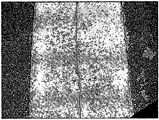
- FIG. 2 is a photograph showing a state where a crack occurs in the center portion of a conventional feeder.
- the conventional ferrite core module has a vertical core part (not shown) arranged in a line at a center with a predetermined interval in the vehicle traveling direction.
- a bending load acts on both sides of the vertical core part when the vehicle passes, causing cracks on the surface of the middle part of the feeding road
- FIG. 2 is a photograph showing a state where cracks are formed on the surface of the middle part of the feeding road.
- the conventional power supply road structure has a problem that cracks are caused by bending in the longitudinal direction (vehicle progress direction) by receiving a load repeatedly applied to the road as the vehicle passes.
- the first object of the present invention is to change the structure of the ferrite core module, thereby preventing cracks occurring on the surface of the middle portion of the feed, and the output than conventional ferrite core module
- the present invention provides a ferrite core structure for a power feeding device of an electric vehicle that can be improved.
- the second purpose of the ferrite for electric power feeding device of the electric vehicle that can prevent the occurrence of cracks on the road by reducing the strength decrease due to the bending in the vehicle traveling direction by the load repeatedly applied to the road due to the traffic of the vehicle.
- An object of the present invention as described above is arranged to be spaced apart a plurality of horizontal core portion to prevent magnetic flux leakage to the ground;
- a plurality of first vertical core portions extending from both ends of the horizontal core portion in an upward direction of the horizontal core portion to prevent magnetic flux leakage to the outer surface;
- At least two rows of second vertical core portions formed so as to extend in an upward direction from the center portion of the horizontal core portion and arranged in a direction parallel to the first vertical core portion;
- a first support part supporting the first vertical core part by interconnecting the plurality of first vertical core parts, wherein the ferrite core structure for a power feeding device of an electric vehicle is provided.
- the horizontal core portion, the first vertical core portion and the second vertical core portion may be made of a ferrite material.
- each row forming the second vertical core portion may be provided to be spaced apart from each other.
- the ferrite core structure may further include a second support part supporting the horizontal core part by interconnecting the plurality of horizontal core parts.
- an object of the present invention is a ferrite core structure for a power feeding device of the electric vehicle; And at least one reinforcing bar embedded below the ferrite core structure to be spaced apart from the ferrite core structure.
- the rebar may be characterized in that it is embedded in the longitudinal direction (vehicle progress direction) of the feed road.
- the reinforcing bar may be characterized in that the diameter is 19mm or more.
- the present invention first, by changing the structure of the ferrite core module, there is an effect that can prevent the cracks generated on the surface of the middle portion of the feed, and improve the output than the conventional ferrite core module.
- FIG. 1 is a perspective view showing a general feed rail for generating a magnetic field for charging a conventional non-contact magnetic induction charging type electric vehicle
- FIG. 2 is a photograph showing a state where a crack occurs in the center portion of a conventional feeder
- FIG. 3 is a perspective view showing a ferrite core structure for a power feeding device of an electric vehicle according to an embodiment of the present invention
- FIG. 4 is a cross-sectional view of a ferrite core structure 100 for a power feeding device of an electric vehicle according to an embodiment of the present invention
- FIG. 5 is a perspective view showing a ferrite core structure and a reinforcing bar for a power feeding device of an electric vehicle embedded in a ground according to an embodiment of the present invention
- FIG. 6 is a cross-sectional view of a feed road structure in which a ferrite core structure and reinforcing bars are embedded according to an embodiment of the present invention.
- FIGS. 3 and 4 are perspective views showing a ferrite core structure for a power feeding device of an electric vehicle according to an embodiment of the present invention
- Figure 4 is a cross-sectional view of the ferrite core structure for a power feeding device of an electric vehicle according to an embodiment of the present invention.
- the ferrite core structure 100 (hereinafter, referred to as a “core structure”) for a power feeding device of an electric vehicle according to the present invention includes a horizontal core part 110 and a first vertical core part 120. ), A second vertical core portion 130 and a first support portion 140.
- the horizontal core part 110 is arranged to be spaced apart from each other, and serves to prevent magnetic flux leakage to the lower ground.
- the interval at which the horizontal core portion 110 is spaced apart is sufficiently smaller than the gap interval indicating the distance between the surface of the feed road and the vehicle current collecting module. This is because when the separation distance of the horizontal core portion 110 is sufficiently smaller than the gap interval, there is almost no attenuation of the magnetic field, so that the effect as if the horizontal core portions 110 are continuously arranged can be obtained.
- the first vertical core portion 120 is formed to extend in the upward direction of the horizontal core portion 110 from both ends of the horizontal core portion 110, the magnetic flux to the outer surface of the first vertical core portion 120 It serves to prevent leakage. That is, the horizontal core part 110 and the first vertical core part 120 prevent the magnetic flux from leaking in the lower and lateral directions of the core structure 110 so that the magnetic flux can be concentrated in the upper direction of the core structure 100. This is because the strength of the magnetic field can be maximized.
- the second vertical core portion 130 is formed to extend in an upward direction of the horizontal core portion 110 from the center portion of the horizontal core portion 110.
- the second vertical core portion 130 is arranged in a direction parallel to the first vertical core portion 120 and may be composed of a plurality of rows or more, but is preferably composed of two rows.
- the second vertical core portion 130 distributes the bending loads acting on both sides of the second vertical core portion 130 to prevent the occurrence of cracks on the surface of the intermediate portion as a feed. That is, since the second vertical core portion 130 is composed of a plurality of rows spaced at regular intervals, the cracks are generated on the surface of the intermediate portion by feeding the buffer zone between the rows and the rows of the second vertical core portion 130. It is to prevent the role.
- the plurality of second vertical core portion 130 may be coupled to the horizontal core portion 110 by using an adhesive, and after the second vertical core portion 130 is made of '' 'shaped individual, The open portion of the individual may be fitted to the horizontal core portion 110 in which an empty space in which the individual may be inserted is formed so as to face upward, and then may be combined using an adhesive.
- the horizontal core unit 110 and the second vertical core unit 130 may be fabricated and used integrally.
- each row forming the second vertical core portion 130 is provided to be spaced apart from each other, the interval between each row may be 1 to 10cm, it is particularly preferred to be spaced apart about 4cm. This is because when the spaced interval is too narrow or wide, the bending load acting on both sides of the second vertical core portion 130 cannot be effectively distributed.
- the intervals of the columns constituting the second vertical core portion 130 may be variously adjusted.
- the second vertical core portion 130 in a plurality of rows, it is possible to obtain an effect of further providing means for preventing the magnetic flux in the core structure 100 from leaking to the outer surface of the core structure 100. . That is, by enhancing the function of preventing the magnetic flux to the outer surface of the core structure 100 to leak, it is possible to further concentrate the magnetic flux in the upper direction of the core structure (100).
- the horizontal core portion 110, the first vertical core portion 120 and the second vertical core portion 130 is made of a ferrite material. Meanwhile, a power feeding line is provided between the horizontal core part 110, the first vertical core part 120, and the second vertical core part 130 to form a magnetic field by supplying electrical energy (not shown). city).
- the first support part 140 serves to connect and support the first vertical core part 120.
- the first support portion 140 may be formed along the inner and outer surfaces of the end portion of the first vertical core portion 120, and may be provided at other portions of the intermediate portion other than the end portion of the first vertical core portion 120. It may be.
- the first support part 140 may be made of a ferrite material, and may be formed of various materials such as iron or an alloy. Meanwhile, the first support part 140 may be coupled to the first vertical core part 120 using an adhesive.
- the core structure 100 may further include a second support part 150 supporting the horizontal core part 110 by interconnecting the plurality of horizontal core parts 110. Since the description of the second support part 150 overlaps with the description of the first support part 140, a detailed description thereof will be omitted.
- FIG. 5 is a perspective view illustrating a ferrite core structure and reinforcing bars for a power feeding device of an electric vehicle embedded in ground according to an embodiment of the present invention
- FIG. 6 is a ferrite core structure and reinforcing bars embedded according to an embodiment of the present invention.
- the feeding road structure in which the core structure 100 and the reinforcement 160 are embedded includes a horizontal core part 110 and a first vertical core part.
- the core structure 100 including the 120, the second vertical core part 130, the first support part 140, and the second support part 150 is spaced apart from the core structure 100 at a lower portion of the core structure 100. It is composed of reinforcement 160 is embedded.
- the road structure is a modification, the core structure 100 and the reinforcing bar consisting of a horizontal core portion 110, the first vertical core portion 120, the second vertical core portion 130 and the first support portion 140 160) (not shown). Since the core structure 100 has already been described, only the reinforcement 160 will be described below.
- Reinforcing bar 160 is embedded in the longitudinal direction (vehicle progress direction) of the feed road.
- the number of the reinforcement 160 is buried may be one or more, it is possible to adjust the number of the reinforcement 160 is buried according to the conditions of the feed road.
- the diameter of the reinforcing bar 160 used is small, the number of reinforcing bars 160 may be increased.
- the number of reinforcing bars 160 may be reduced. In FIG. 6, for example, four rebars 160 are embedded.
- the reinforcing bar 160 having a diameter of 19 mm or more. This is because when the reinforcement 160 is less than 19 mm, the strength decrease due to the bending in the vehicle traveling direction cannot be effectively reduced by the load repeatedly applied to the road due to the traffic of the vehicle. That is, when the reinforcement 160 is less than 19 mm, the load applied to the road cannot be sustained, and the reinforcement 160 is also bent in the vehicle traveling direction, so that cracks cannot be prevented from occurring on the road.
- [Table 1] is a measurement result table of the conventional ferrite core module
- [Table 2] is a core structure having a second vertical core portion 130, each row is arranged 4cm apart in accordance with an embodiment of the present invention It is a measurement result table of (100).
- the feed currents of 94 (A) and 130 (A) were used, and the measurement position of the EMF (Electro-Magnetic Field) was measured 1.2m away from the center of the current collector, and the distance between the road surface and the vehicle current collector module was measured.
- the pore shown was 25 cm, and the output and the EMF were measured.
- the core structure having the second vertical core portion structured as shown in the present invention shows improved results in the output and EMF compared to the conventional ferrite core module.
- the feed current of 130 (A) rather than 94 (A) the size of the EMF is improved compared to the conventional ferrite core module.
Landscapes
- Engineering & Computer Science (AREA)
- Power Engineering (AREA)
- Mechanical Engineering (AREA)
- Transportation (AREA)
- Electric Propulsion And Braking For Vehicles (AREA)
- Current-Collector Devices For Electrically Propelled Vehicles (AREA)
- Regulation Of General Use Transformers (AREA)
- Charge And Discharge Circuits For Batteries Or The Like (AREA)
- Coils Or Transformers For Communication (AREA)
Abstract
Priority Applications (6)
| Application Number | Priority Date | Filing Date | Title |
|---|---|---|---|
| SG2013057773A SG192207A1 (en) | 2011-04-13 | 2012-04-13 | Ferrite core structure for a power supply device of an electric vehicle and power supply road structure using same |
| AU2012243545A AU2012243545B2 (en) | 2011-04-13 | 2012-04-13 | Ferrite core structure for a power supply device of an electric vehicle and power supply road structure using same |
| EP12771721.3A EP2698801B1 (fr) | 2011-04-13 | 2012-04-13 | Structure de noyau en ferrite pour dispositif d'alimentation en énergie d'un véhicule électrique, et structure de route d'alimentation en énergie qui utilise cette structure de noyau |
| JP2014501019A JP5653560B2 (ja) | 2011-04-13 | 2012-04-13 | 電気自動車の給電装置用フェライトコア構造体及びこれを用いた給電道路構造 |
| CN201280014229.XA CN103460313B (zh) | 2011-04-13 | 2012-04-13 | 电动汽车供电装置的铁氧体磁芯结构及利用其的供电道路结构 |
| US14/111,539 US9552922B2 (en) | 2011-04-13 | 2012-04-13 | Ferrite core structure for a power supply device of an electric vehicle and power supply road structure using same |
Applications Claiming Priority (2)
| Application Number | Priority Date | Filing Date | Title |
|---|---|---|---|
| KR1020110034168A KR101226525B1 (ko) | 2011-04-13 | 2011-04-13 | 전기자동차의 급전장치용 페라이트 코어 구조체 및 이를 이용한 급전 도로구조체 |
| KR10-2011-0034168 | 2011-04-13 |
Publications (2)
| Publication Number | Publication Date |
|---|---|
| WO2012141512A2 true WO2012141512A2 (fr) | 2012-10-18 |
| WO2012141512A3 WO2012141512A3 (fr) | 2013-01-03 |
Family
ID=47009847
Family Applications (1)
| Application Number | Title | Priority Date | Filing Date |
|---|---|---|---|
| PCT/KR2012/002789 Ceased WO2012141512A2 (fr) | 2011-04-13 | 2012-04-13 | Structure de noyau en ferrite pour dispositif d'alimentation en énergie d'un véhicule électrique, et structure de route d'alimentation en énergie qui utilise cette structure de noyau |
Country Status (8)
| Country | Link |
|---|---|
| US (1) | US9552922B2 (fr) |
| EP (1) | EP2698801B1 (fr) |
| JP (1) | JP5653560B2 (fr) |
| KR (1) | KR101226525B1 (fr) |
| CN (1) | CN103460313B (fr) |
| AU (1) | AU2012243545B2 (fr) |
| SG (1) | SG192207A1 (fr) |
| WO (1) | WO2012141512A2 (fr) |
Cited By (1)
| Publication number | Priority date | Publication date | Assignee | Title |
|---|---|---|---|---|
| US10512771B2 (en) | 2013-11-10 | 2019-12-24 | Brainsgate Ltd. | Implant and delivery system for neural stimulator |
Families Citing this family (5)
| Publication number | Priority date | Publication date | Assignee | Title |
|---|---|---|---|---|
| KR101570912B1 (ko) * | 2013-12-18 | 2015-11-20 | 주식회사 올레브 | 급전선로 조립체 및 이를 이용한 시공방법 |
| KR101589609B1 (ko) * | 2014-08-21 | 2016-01-29 | 한국과학기술원 | 무선 전력공급장치 |
| KR101794185B1 (ko) * | 2015-10-30 | 2017-11-08 | 한국기술교육대학교 산학협력단 | 전기자동차의 급전장치용 코어 구조체 |
| CN108695989A (zh) * | 2018-06-25 | 2018-10-23 | 哈尔滨工业大学 | 一种用于动态无线充电的分段式双极型发射导轨 |
| CN108683272B (zh) * | 2018-06-25 | 2021-07-30 | 哈尔滨工业大学 | 一种用于动态无线充电的双极型发射导轨 |
Family Cites Families (7)
| Publication number | Priority date | Publication date | Assignee | Title |
|---|---|---|---|---|
| JP2000116035A (ja) * | 1998-09-29 | 2000-04-21 | Yamaha Motor Co Ltd | 輸送設備 |
| FR2800020B1 (fr) * | 1999-10-25 | 2003-10-03 | Alstom | Systeme d'alimentation statique par le sol pour vehicule electrique et vehicule electrique destine a etre alimente au moyen d'un tel systeme d'alimentation |
| JP2004363137A (ja) * | 2003-06-02 | 2004-12-24 | Hitachi Communication Technologies Ltd | プリント基板保持装置 |
| JP4209437B2 (ja) * | 2006-11-10 | 2009-01-14 | 三菱重工業株式会社 | 移動体の非接触給電装置及びその保護装置 |
| KR100944113B1 (ko) * | 2009-02-27 | 2010-02-24 | 한국과학기술원 | 전기자동차용 전원공급 시스템 및 방법 |
| KR101040662B1 (ko) * | 2009-04-06 | 2011-06-13 | 한국과학기술원 | 전기자동차용 초박형 급전장치와 집전장치 |
| KR101056169B1 (ko) * | 2009-12-22 | 2011-08-11 | 한국과학기술원 | 비접촉 자기 유도 충전 방식 전기자동차의 급전장치용 페라이트코어 모듈 |
-
2011
- 2011-04-13 KR KR1020110034168A patent/KR101226525B1/ko not_active Expired - Fee Related
-
2012
- 2012-04-13 EP EP12771721.3A patent/EP2698801B1/fr active Active
- 2012-04-13 US US14/111,539 patent/US9552922B2/en active Active
- 2012-04-13 WO PCT/KR2012/002789 patent/WO2012141512A2/fr not_active Ceased
- 2012-04-13 CN CN201280014229.XA patent/CN103460313B/zh active Active
- 2012-04-13 JP JP2014501019A patent/JP5653560B2/ja active Active
- 2012-04-13 SG SG2013057773A patent/SG192207A1/en unknown
- 2012-04-13 AU AU2012243545A patent/AU2012243545B2/en active Active
Non-Patent Citations (2)
| Title |
|---|
| None |
| See also references of EP2698801A4 |
Cited By (1)
| Publication number | Priority date | Publication date | Assignee | Title |
|---|---|---|---|---|
| US10512771B2 (en) | 2013-11-10 | 2019-12-24 | Brainsgate Ltd. | Implant and delivery system for neural stimulator |
Also Published As
| Publication number | Publication date |
|---|---|
| EP2698801A4 (fr) | 2015-12-23 |
| EP2698801B1 (fr) | 2021-02-17 |
| AU2012243545A1 (en) | 2013-08-15 |
| EP2698801A2 (fr) | 2014-02-19 |
| US20140217829A1 (en) | 2014-08-07 |
| JP5653560B2 (ja) | 2015-01-14 |
| AU2012243545B2 (en) | 2015-01-29 |
| KR20120116622A (ko) | 2012-10-23 |
| KR101226525B1 (ko) | 2013-01-25 |
| CN103460313B (zh) | 2016-04-06 |
| SG192207A1 (en) | 2013-09-30 |
| JP2014515182A (ja) | 2014-06-26 |
| CN103460313A (zh) | 2013-12-18 |
| US9552922B2 (en) | 2017-01-24 |
| WO2012141512A3 (fr) | 2013-01-03 |
Similar Documents
| Publication | Publication Date | Title |
|---|---|---|
| WO2012141512A2 (fr) | Structure de noyau en ferrite pour dispositif d'alimentation en énergie d'un véhicule électrique, et structure de route d'alimentation en énergie qui utilise cette structure de noyau | |
| WO2010117139A2 (fr) | Dispositif d'alimentation électrique ultrafin et dispositif d'acquisition électrique pour un véhicule électrique | |
| WO2011078552A2 (fr) | Appareil collecteur de courant comprenant une fonction de protection cem active pour véhicule électrique en ligne | |
| KR101794901B1 (ko) | 유도 전력 전송 장치 | |
| CN109094422B (zh) | 悬挂式轨道交通设备以及其中的磁电混合悬浮轨系统 | |
| WO2010098547A2 (fr) | Dispositif d'alimentation électrique, dispositif d'acquisition d'énergie et système de sécurité pour un véhicule électrique entraîné par induction électromagnétique | |
| ATE376750T1 (de) | Vertikales kabelverteilersystem mit rippengerüstkonstruktion | |
| WO2019168360A1 (fr) | Bobine à angle plat présentant une forme tridimensionnelle permettant de maximiser le facteur de remplissage, et moteur électrique comprenant une telle bobine | |
| WO2020138654A1 (fr) | Transformateur de courant de disjoncteur à air | |
| WO2011043628A2 (fr) | Appareil d'alimentation électrique pour véhicule électrique connecté | |
| KR102249729B1 (ko) | 전기차량 및 산업용 장비의 주행 중 무선충전 급전 및 집전 시스템 | |
| WO2016027982A1 (fr) | Appareil d'alimentation electrique sans fil | |
| KR101879938B1 (ko) | 역자기장선을 이용한 전기자동차용 급전장치 구조 | |
| WO2017000545A1 (fr) | Structure de sortie haute tension de réacteur en dérivation ultra-haute tension | |
| WO2017073938A1 (fr) | Structure centrale pour dispositif d'alimentation de véhicule électrique | |
| CN215947888U (zh) | 伸缩缝处弱电管道保护装置和桥梁结构 | |
| WO2009093841A2 (fr) | Barre omnibus à branche horizontale et conduite omnibus comprenant une telle barre | |
| KR20180120820A (ko) | 전기자동차용 단거리 무선전력전송 급전장치 | |
| WO2020159324A1 (fr) | Système d'alimentation électrique et de collecte de courant pour charge sans fil sur route d'un véhicule électrique et machine industrielle | |
| KR101259155B1 (ko) | 전기자동차용 집전장치 | |
| WO2022005250A1 (fr) | Bobines multiples de collecte de courant pour la charge sans fil de véhicules électriques et équipements industriels et dispositif de collecte de courant les comprenant | |
| CN207719116U (zh) | 一种断路器抽屉座 | |
| CN211556428U (zh) | 一种二次设备预制舱内防静电装置 | |
| WO2020159323A1 (fr) | Système de charge et d'alimentation sans fil pendant la conduite d'un véhicule électrique et équipement industriel | |
| NO20015280D0 (no) | Elektrisitetsforsyningssystem for trekkraft |
Legal Events
| Date | Code | Title | Description |
|---|---|---|---|
| WWE | Wipo information: entry into national phase |
Ref document number: 201280014229.X Country of ref document: CN |
|
| 121 | Ep: the epo has been informed by wipo that ep was designated in this application |
Ref document number: 12771721 Country of ref document: EP Kind code of ref document: A2 |
|
| ENP | Entry into the national phase |
Ref document number: 2012243545 Country of ref document: AU Date of ref document: 20120413 Kind code of ref document: A |
|
| ENP | Entry into the national phase |
Ref document number: 2014501019 Country of ref document: JP Kind code of ref document: A |
|
| NENP | Non-entry into the national phase |
Ref country code: DE |
|
| WWE | Wipo information: entry into national phase |
Ref document number: 14111539 Country of ref document: US |