WO2012144005A1 - Âme de fibre optique recouverte de plastique et câble de fibre optique - Google Patents
Âme de fibre optique recouverte de plastique et câble de fibre optique Download PDFInfo
- Publication number
- WO2012144005A1 WO2012144005A1 PCT/JP2011/059561 JP2011059561W WO2012144005A1 WO 2012144005 A1 WO2012144005 A1 WO 2012144005A1 JP 2011059561 W JP2011059561 W JP 2011059561W WO 2012144005 A1 WO2012144005 A1 WO 2012144005A1
- Authority
- WO
- WIPO (PCT)
- Prior art keywords
- core
- optical fiber
- clad
- glass
- diameter
- Prior art date
- Legal status (The legal status is an assumption and is not a legal conclusion. Google has not performed a legal analysis and makes no representation as to the accuracy of the status listed.)
- Ceased
Links
Images



Classifications
-
- G—PHYSICS
- G02—OPTICS
- G02B—OPTICAL ELEMENTS, SYSTEMS OR APPARATUS
- G02B6/00—Light guides; Structural details of arrangements comprising light guides and other optical elements, e.g. couplings
- G02B6/02—Optical fibres with cladding with or without a coating
- G02B6/02033—Core or cladding made from organic material, e.g. polymeric material
-
- G—PHYSICS
- G02—OPTICS
- G02B—OPTICAL ELEMENTS, SYSTEMS OR APPARATUS
- G02B1/00—Optical elements characterised by the material of which they are made; Optical coatings for optical elements
- G02B1/04—Optical elements characterised by the material of which they are made; Optical coatings for optical elements made of organic materials, e.g. plastics
- G02B1/045—Light guides
- G02B1/048—Light guides characterised by the cladding material
Definitions
- the present invention relates to a plastic-clad optical fiber and an optical fiber cable, and more particularly, a plastic-clad optical fiber used in a USB cable, an HDMI cable (or cord), a cellular phone, etc. And an optical fiber cable.
- HPCF core hard polymer clad fiber core
- the HPCF core is formed by coating a fluororesin having a refractive index lower than that of a glass having a core diameter of 195 to 205 ⁇ m made of quartz glass as a cladding layer having a thickness of about 15 ⁇ m to form an HPCF strand. is doing.
- a resin coating layer made of a fluorine-based thermoplastic resin is extrusion-coated to form an HPCF core wire having an outer diameter of 0.5 mm or 0.9 mm.
- the HPCF core wire has a large transmission loss, but has a large core diameter, a high coupling efficiency between the pulse light source and the light receiver, and is easy to connect, so it is used in short distance fields such as FA (Factory Automation). .
- HPCF cores are required to have no increase in transmission loss even when wound around a bobbin or when the ambient temperature changes.
- HPCF cores with a core diameter of 200 ⁇ m or more increase transmission loss when bent to a small diameter. To do.
- the allowable bending radius is generally limited to 15 mm or more. For this reason, the HPCF core wire requires caution when wiring, and although it could be used in a factory, it could not be used for wiring between devices in a general home or office. .
- the object of the present invention has been made to solve the above-mentioned problems, and as an inter-device wiring cable such as a USB cable or an HDMI cable, even if it is bent to a small diameter (bending radius 2 mm), the amount of increase in transmission loss is small. It is to provide a plastic clad optical fiber core and an optical fiber cable.
- to provide a plastic clad optical fiber and an optical fiber cable that can be used safely in ordinary homes and offices without worrying about core breakage even when placed in a bent state for a long period of time. is there.
- the configuration of the present invention is as follows. (1) A plastic clad light in which a coating layer made of a thermoplastic resin is formed on a plastic clad optical fiber in which a clad layer made of a resin having a refractive index lower than that of the core glass is formed on the outer periphery of the core glass made of quartz glass. A plastic-clad optical fiber, wherein the core glass has a core diameter of 50 to 100 ⁇ m and a relative refractive index difference of the core glass with respect to the cladding layer is 3.7% or more. line.
- the diameter of the cladding layer is preferably 1.4 to 2.5 times the core diameter.
- the plastic clad optical fiber preferably has a static fatigue coefficient of 22 or more.
- the plastic clad optical fiber core and the optical fiber cable of the present invention transmission loss due to bending is small. Further, even if the ambient temperature changes, the transmission loss is small and the connection loss is small. Furthermore, as a USB cable or HDMI cable, there is no risk of core breakage even when bent to a bending radius of 2 mm or less, and the break probability can be reduced to 10 ⁇ 6 or less, so that it can be used with peace of mind in ordinary homes and offices. . It can also be used for high-speed transmission at 10 Gbps.
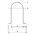
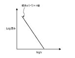
- FIG. 1 It is a schematic sectional drawing which shows an example of the plastic clad optical fiber core wire of this invention. It is explanatory drawing which shows the refractive index distribution of the plastic clad optical fiber strand of FIG. It is a figure which shows how to obtain
- the PCF core wire 1 is made of a core glass 2 made of quartz glass and an ultraviolet curable fluororesin such as an ultraviolet curable fluorinated acrylate resin which is a resin having a lower refractive index than the core glass 2. And a clad layer 3 surrounding the outer peripheral surface of the core glass 2 and a plastic clad optical fiber strand (hereinafter referred to as PCF strand) 4 composed of the clad layer 3.
- a resin coating layer 5 made of a fluorine-based thermoplastic resin such as ethylene-tetrafluoroethylene copolymer (ETFE) is formed on the outer periphery of the cladding layer 3.
- ETFE ethylene-tetrafluoroethylene copolymer
- Core diameter d1 of core glass 2 50 to 100 ⁇ m Clad diameter d2 of the clad layer 3: 90 to 175 ⁇ m Thickness t of clad layer 3: 20 to 37.5 ⁇ m Cladding diameter d2 / core diameter d1: 1.4 to 2.5 Outer diameter of resin coating layer 5: 250 to 500 ⁇ m
- the refractive index of the core glass 2 of the PCF strand 4 is increased by adding germanium (Ge).
- the refractive index distribution of the core glass 2 is such that the relative refractive index difference ⁇ increases toward the center from the outer peripheral surface, and the graded index (GI) at which the relative refractive index difference ⁇ is maximum (A level) at the center of the core glass 2.
- the relative refractive index difference ⁇ on the outer periphery of the core glass is zero (B level) compared to pure silica.
- the refractive index of the cladding layer 3 is lowered by adding fluorine.
- the core glass relative refractive index difference with respect to the cladding layer is 3.7% or more.
- the numerical aperture of the PCF core wire of the present invention is preferably 0.40 or more.
- the resin for the clad layer 3 has a low refractive index with respect to the core glass 2 and needs to be cured with active energy rays such as ultraviolet rays. Furthermore, it is necessary to be a resin from which a cured product excellent in mechanical strength, flexibility and transparency can be obtained by curing.
- Such resins include (a) (meth) acrylate monomers or polymers containing fluorine atoms in the molecule, (b) (meth) acrylate monomers or polymers, (c) core materials and chemicals. It is preferable to use a resin composition comprising a coupling agent that forms a bond and (d) a photopolymerization initiator.
- a desired refractive index can be obtained by changing the number of fluorine atoms in the molecule of the component (a) or the component, or changing the concentration of the component (a) in the resin composition.
- the (meth) acrylate monomer (a1) containing a fluorine atom in the molecule a substance represented by the following chemical formula (A) or a compound represented by chemical formulas (B1) to (B3) having two or more unsaturated bonds Substances.
- (meth) acrylate polymer (a2) containing a fluorine atom for example, an ester side chain unsaturated bond represented by the following chemical formula (C) having a number average molecular weight of 50,000 to 5,000,000 (in terms of styrene) (Meth) acrylate copolymer having
- R1 and R2 each represents hydrogen or a methyl group
- Rf represents a fluoroalkyl group
- Rx represents a hydrocarbon group having an unsaturated bond.
- examples of the Rx group include a vinyl group, an allyl group, an acrylic group, a methacryl group, and an internal olefin.
- the Rf group includes — (CH2) a- (CF2) b—CF3. [Wherein, a is 1 or 2, and b is 2-6. ] Can be illustrated.
- Examples of the (meth) acrylate monomer (b) include the following compounds as crosslinkable, that is, those having two or more unsaturated bonds: 1,4-butanediol di (meth) acrylate, ethylene glycol di (meth) acrylate, glycerol dimethacrylate, tetraethylene glycol di (meth) acrylate, diethylene glycol di (meth) acrylate, 1,3-butylene glycol di (meth) Acrylate, neopentyl glycol di (meth) acrylate, triethylene glycol di (meth) acrylate, triglycerol diacrylate, 1,6-hexanediol di (meth) acrylate, tripropylene glycol diacrylate, trimethylolpropane tri (meth) Acrylate, pentaerythritol triacrylate, pentaerythritol tetra (meth) acrylate, ditrimethylolpropan
- Examples of the coupling agent (c) include the following compounds: Trimethoxyvinylsilane, methacryloxypropyltrimethoxysilane, dimethylethoxyvinylsilane, etc.
- Examples of compounds having two or more unsaturated bonds in the molecule include the following compounds: Diethoxydivinylsilane, dimethoxydivinylsilane, dimethacryloxypropyltrimethoxysilane, etc.
- the photopolymerization initiator (d) is preferably a compound that easily generates radicals upon irradiation with ultraviolet light, and includes the following compounds: Benzophenone, acetophenone, benzyl, benzoin, benzoin methyl ether, benzoin isobutyl ether, benzyl dimethyl ketal, ⁇ , ⁇ '-azobisisobutyronitrile, benzoyl peroxide, 1-hydroxycyclohexyl phenyl ketone, 2,2-dimethoxy-2 -Phenylacetophenone, 2-hydroxy-2-methyl-1-phenylpropan-1-one.
- the resin composition having the above-described structure is preferably a resin liquid, and the clad layer 3 is manufactured by applying the resin liquid to the core and further irradiating with ultraviolet rays.
- the resin liquid is preferably applied by a die coating method.
- the resin coating layer 5 is formed of a resin composition made of a thermoplastic resin having high heat resistance.
- the thermoplastic resin include ethylene-tetrafluoroethylene copolymer (ETFE).
- ETFE ethylene-tetrafluoroethylene copolymer
- it may be an ultraviolet curable resin such as a urethane acrylate resin or a resin obtained by blending an epoxy acrylate resin or a polyester acrylate resin with a urethane acrylate resin.
- the PCF core wire 1 is a light having a wavelength of 850 nm when bent to a radius of 2 mm by setting the core diameter d1 of the core glass 2 to 50 to 100 ⁇ m and the relative refractive index difference of the core with respect to the cladding to 3.7% or more.
- the transmission loss increase amount can be 0.4 dB / 10 turns or less.
- the PCF core wire 1 can reduce the increase in transmission loss of light having a wavelength of 850 nm due to a temperature change of ⁇ 40 ° C. to 85 ° C. by setting the thickness of the cladding layer to 20 ⁇ m or more. .
- the microbend loss increases, and the increase in transmission loss due to changes in ambient temperature is considered to increase.
- the increase in the transmission loss due to the temperature change is the increase in the transmission loss after 10 times of the heat cycle in which the temperature of the atmosphere in which the test article is placed is changed from room temperature ⁇ 80 ° C. ⁇ ⁇ 45 ° C. ⁇ room temperature. is there. Hold at 80 ° C. and ⁇ 45 ° C.
- the thickness of the cladding layer is 20 ⁇ m when the core diameter is 100 ⁇ m, the ratio of the cladding diameter / core diameter becomes the minimum value of 1.4.
- the connection is made so that the outer circumferences of the clads coincide.
- the cores are deviated and connected.
- the light transmitted through the core leaks at the connection location, and the connection loss increases.
- the thickness of the clad is 37.5 ⁇ m or less, the amount of deviation of the core center from the clad center is small, and the connection loss of light having a wavelength of 850 nm can be within a practically problematic range (0.5 dB or less).
- the thickness of the cladding layer is preferably 37.5 ⁇ m or less.
- the ratio of clad diameter / core diameter becomes a maximum value of 2.5.
- the optical fiber If the optical fiber is placed in a bent state for a long time, it may break due to static fatigue. USB cables and HDMI cables are often placed in a bent state. Therefore, it is desired that the PCF strands used for these cables have a low probability of static fatigue fracture even when placed for a long time in a bent state.
- the PCF strand of the present invention preferably has a breaking probability of 10 ⁇ 6 (1 ppm) or less.
- the fracture probability F can be obtained from the static fatigue coefficient (n value) by the following formula.
- F 1-exp (X)
- X ⁇ Np ⁇ L ⁇ m / (n ⁇ 2) ⁇ ( ⁇ s / ⁇ p) n ⁇ (ts / tp)
- Np Fracture frequency during fiber production
- L Installation length
- m Weibull distribution coefficient when the crack number distribution N follows the Weibull distribution
- ⁇ s Core distortion during installation
- ⁇ p Core distortion during screening during fiber manufacture
- ts warranty period
- tp screening load time during fiber production
- F ⁇ X.
- F Np ⁇ L ⁇ m / (n-2) ⁇ ( ⁇ s / ⁇ p) n ⁇ (ts / tp) ⁇ ( ⁇ s / ⁇ p) n ⁇ ⁇ s n
- the n value is obtained from the following method.
- a PCF strand is wound 1 m at a time on several types of mandrels with different radii and left unattended.
- the mandrel diameter is, for example, 1.6 mm, 1.8 mm, 1.9 mm, and 2.0 mm.
- the number of samples is, for example, 15 for each diameter mandrel.
- the time required for the PCF strand of each sample to break is measured.
- (2) Determine the median value of the rupture time (time tf at which 50% of the samples break). When the number of samples is 15, the fracture time of the eighth fractured sample is tf.
- the strain applied to the glass (core layer) is calculated from the diameter T of the mandrel, the glass diameter (core diameter d1) of the PCF, and the cladding diameter d2 using the following calculation formula.
- the log distortion vs. logtf is plotted to determine the slope of the graph. Multiplying this slope by -1 gives the n value.
- the n value can be adjusted as follows. (1) Remove uncured components from the cladding layer. (2) Slowly cool during drawing. (3) After coating the core with carbon, a cladding layer is formed on the outer periphery thereof.
- the resin composition forming the clad layer may contain a non-hardening component such as a substance represented by the following chemical formula (1) in order to improve heat resistance.
- the cladding layer contains a non-hardening component such as the above chemical formula, it hinders the improvement of the static fatigue coefficient. Therefore, it is preferable not to include a non-hardening component such as the above chemical formula in the cladding layer.
- the method for drawing PCF strands is as follows. First, the glass base material is heated and softened, and drawn to a predetermined diameter. This part is the core. Next, a liquid clad material is applied to the core. Specifically, the cladding material can be applied to the outer periphery of the core by passing the glass fiber as the core through a die containing the cladding material. Next, the clad material is cured by irradiating the applied clad material with ultraviolet rays.
- the glass base material is heated to a few thousand to about 2,000 ° C. for softening.
- the drawn glass fiber is air-cooled and cooled to several tens of degrees Celsius. At this time, the cooling rate of the drawn glass fiber is decreased. That is, the glass fiber can be further cooled to further reduce microscopic scratches on the surface of the glass fiber, and the static fatigue coefficient of the PCF strand can be 30 or more.
- gradually cooling the glass fiber it is possible to pass the glass fiber being cooled through a cylindrical container.
- the temperature of the container may be set to 500 ° C. to 1500 ° C. so that the glass fiber is not rapidly cooled, and it is not particularly necessary to control the temperature.
- the difference between the temperature when the glass fiber enters the container (input temperature) and the temperature when it exits (output temperature) divided by the time required for the glass fiber to pass through the container is the slow cooling rate. is there. If the slow cooling rate is lower than the cooling rate when the glass fiber is cooled from the incoming line temperature to the outgoing line temperature without the container, it can be said that the glass fiber has been gradually cooled.
- the static fatigue coefficient can be increased to about 300 by forming a cladding layer on the outer periphery of the glass fiber after carbon coating.
- carbon coating the glass fiber it is possible to pass the glass fiber immediately after drawing through a reaction furnace containing a raw material gas.
- the raw material gas reacts with the heat of the glass fiber by a thermal chemical vapor deposition method (thermal CMD method), and the carbon layer is coated on the surface of the glass fiber.
- hydrocarbons such as ethylene, acetylene, and chloroform, and halogen carbon hydrocarbons are used.
- silane gas a compound made of silicon, hydrogen, halogen, etc., such as SiH 4 , SiHCl 3 , and SiCl 4 may be mixed.
- the manufactured PCF strand becomes a PCF core wire by extruding a resin coating layer such as ETFE or coating an ultraviolet curable resin.
- the PCF core wire of the present invention can be made into an optical cable by further placing it in a PVC tube.
- the optical cable may have a loose structure in which one or a plurality of PCF core wires are placed in a tube, and there is no inclusion between the PCF core wire and the tube.
- the optical cable may be formed by attaching a tensile fiber such as Kevlar (registered trademark) around the PCF core wire and forming a jacket with a tube around the fiber.
- the optical cable can also be used for an optoelectric composite cable in which electric wires are arranged around the optical cable and integrated.
- Examples of the PCF strands and PCF cores of the present invention are shown in Table 1 in which the core diameter d1 of the core glass 2 is 50 ⁇ m, 80 ⁇ m, 100 ⁇ m, and the cladding diameter d2 is 120 ⁇ m, 125 ⁇ m, 150 ⁇ m. ⁇ 5.
- the core diameter d1 was 50 ⁇ m, 80 ⁇ m, and 200 ⁇ m
- the clad diameter d2 was 80 ⁇ m, 110 ⁇ m, 150 ⁇ m, and 230 ⁇ m
- Comparative Examples 1 to 4 were selected depending on the combination.
- the PCF core wires of Examples 1 to 5 and Comparative Examples 1 to 4 were formed by extrusion coating ETFE on the resin coating layer on the outer periphery of the PCF strands to have an outer diameter of 500 ⁇ m.
- both the core and the clad were glass (silica), and the outer circumference of the clad was coated with a urethane acrylate resin to form a 250 ⁇ m optical fiber.
- an ETFE layer was coated on the outer periphery of the optical fiber to form an optical fiber core having an outer diameter of 500 ⁇ m.
- the relative refractive index difference (%) of the core with respect to the clad was measured.
- the outgoing NA was calculated from this relative refractive index difference.
- the core was made of quartz (pure silica) with germanium (Ge) added.
- the refractive index of the core is higher than that of pure silica only by the addition of Ge.
- the clad uses a fluorinated acrylate resin, the clad has a refractive index lower than that of pure silica.
- the amount of Ge added was smaller than in Examples 1 to 4, and the refractive index of the core was lowered.
- the cladding material is the same as in Examples 1-5.
- the cores of Comparative Examples 1 to 4 are the same as those of Examples 1 to 4.
- the fluorine concentration of the cladding material was lowered and the refractive index was made higher than that of the examples.
- each comparative example has a smaller relative refractive index difference of the core relative to the cladding than each example.
- the clad of Comparative Example 5 is pure silica, has a higher refractive index than the clads of other examples, and has a small relative refractive index difference of the core with respect to the clad.
- the cladding material of Example 2 and Example 4 is obtained by removing the substance of the chemical formula (1) from the cladding material of Comparative Examples 1 to 4.
- the static fatigue coefficient of Example 2 and Example 4 is 22, which is larger than the static fatigue coefficient of 18 of Comparative Examples 1 to 4.
- Example 3 and Example 5 the core of the PCF core wire was gradually cooled during production. This slow cooling was performed at a cooling rate of 900 ° C./second while the temperature of the optical fiber was changed from 2000 ° C. to 200 ° C.
- the static fatigue coefficient (n value) could be set to 30 by the combination of the slow cooling of the core and the clad material (similar to Example 2 and Example 4).
- the PCF core wire of Example 1 had the same core and clad configuration as those of Example 3 and Example 5, and the core was further carbon-coated (thickness 5 nm). Thereby, Example 1 was able to set the static fatigue coefficient (n value) to 100.
- the static fatigue coefficient (n value) was determined by the method described above.
- the PCF strand was wound around a mandrel having a radius of 2 mm (diameter: 4 mm) for 10 turns, held for 1 minute, stretched once, wound again and held for 1 minute. When this process was repeated 100 times, the probability of the core glass 2 breaking once was determined from the n value. If the fracture probability was 10 ⁇ 6 or less, it was judged to be acceptable, and if it was larger than 10 ⁇ 6 , it was judged to be unacceptable.
- FIG. 4 shows the relationship between the fracture probability and the bending radius.
- the probability of fracture is about 1 ppm when held for 1 minute on a mandrel with a bending radius of 2 mm and repeated 100 times.
- Example 3 in which the core diameter is 80 ⁇ m and the n value is 30, the fracture probability is even smaller.
- Example 2 in which the core diameter is 50 ⁇ m and the n value is 22 has a smaller fracture probability than Example 3 due to the small core diameter.
- the n value should be 22 or more in order to make the fracture probability of the PCF strand having a core diameter of 50 to 100 ⁇ m 1 ppm or less.
- a PCF strand was wound around a mandrel with a radius of 2 mm for 10 turns, and the difference in transmission loss from before winding was taken as an increase in bending loss.
- the wavelength of the signal light was 850 nm, and the transmission loss was determined by the cutback method.
- the bending loss at 10 turns is required to be 1 dB or less due to the configuration of the transmission system. Therefore, the bending loss was determined to be 1 dB / 10 turn or less, and the bending loss was determined to be unacceptable.
- the PCF core wire was coated with a PVC tube with four 1140 denier Kevlars to form an optical cable with an outer diameter of 2 mm.
- This optical cable was subjected to a heat cycle of ⁇ 40 ° C. to 85 ° C.
- the holding time at ⁇ 40 ° C. and 85 ° C. was 4 hours, and the temperature change was 1 ° C./min.
- the difference in transmission loss before being subjected to the heat cycle and after being subjected to the 10-cycle heat cycle is the amount of increase in transmission loss after the temperature change.
- the wavelength of the signal light was 850 nm.
- connection loss For the PCF core wire, a connector was attached, the same kind of PCF core wire was connected, and the loss of the optical signal at the connection location was measured to obtain the connection loss. The wavelength of the signal light was 850 nm.
- the resin coating layer was removed, and the core and the clad were brought into contact at the end face.
- Table 1 shows the measurement results of the PCF core wires of Examples 1 to 5 and Comparative Examples 1 to 5.
- the amount of increase in bending loss when bending to a radius of 2 mm is 0.10 to 0.40 dB / 10 turns in Examples 1 to 5, and the target value is 1 dB / 10 turns. It was a small and practically acceptable range.
- the increase in bending loss when bending to a radius of 2 mm is as large as 1 dB / 10 turns or more, which may cause a problem in the system.
- the cladding is made of glass (Comparative Example 5)
- the amount of increase in bending loss is very large and cannot be practically used.
- the amount of increase in bending loss is smaller than that when the clad is glass.
- the bending loss increase amount is not sufficiently small as in the comparative example.
- the core diameter is large, the amount of increase in bending loss increases, but it can be seen from the examples and comparative examples that the cause of the amount of increase in bending loss in the PCF wire is dominated by the relative refractive index difference between the core and the clad. .
- the amount of increase in transmission loss due to temperature change was 0.02 to 0.08 dB / 100 m in Examples 1 to 5, which was in a practically acceptable range.
- Comparative Examples 2 and 3 the increase in transmission loss after temperature change is large and unsatisfactory, but it is considered that the microbend loss is large due to temperature change. This is presumably because the clad thickness is as thin as 15 ⁇ m.
- Comparative Example 1 it is considered that even if the core diameter is as large as 200 ⁇ m and the cladding is as thin as 15 ⁇ m, the amount of increase in microbend loss due to temperature change does not increase.
- the core diameter is 50 to 100 ⁇ m, the thicker the cladding, the smaller the increase in transmission loss due to temperature change, which is preferable.
- connection loss was 0.5 dB or less, which was in a practically acceptable range.
- Comparative Example 4 although the connection loss is as large as 3.2 dB, it is considered that the clad is too thick. When the clad is thick, the amount of deviation of the center of the core from the center of the clad increases.
- the connection is made so that the outer circumferences of the clads coincide with each other. Therefore, when the center of the core is shifted in each PCF strand to be connected, a step is formed in the waveguide at the connection location. Thereby, it is considered that a part of the light transmitted through the core of one PCF is not incident on the other core and the connection loss increases.
- the core diameter is 50 to 100 ⁇ m
- the connection loss is small when the cladding thickness is 37.5 ⁇ m or less, but the connection loss increases rapidly when the thickness is greater than 37.5 ⁇ m. .
- the PCF core wire (core diameter 50 to 100 ⁇ m) of the present invention preferably has a clad thickness of 20 to 37.5 ⁇ m.
- the ratio of clad diameter / core diameter is preferably 1.4 to 2.5.
- FIG. 5 shows the relationship between the thickness of the cladding and the increase in transmission loss due to temperature change, and the relationship between the thickness of the cladding and the connection loss. Outside this range, transmission loss increases or connection loss increases rapidly due to temperature changes.
- the allowable bending radius is 2 mm.
- the allowable bending radius can be 2 mm or less.
- Comparative Examples 1 to 5 are not preferable in terms of long-term reliability because the allowable bending radius is 2 mm or more.
- Comparative Example 1 having a large core diameter of 200 ⁇ m and Comparative Example 5 in which the cladding is made of glass are not preferable because the fracture is caused in a relatively short time when the bending radius is 2 mm.
- the coupling efficiencies of the PCF wires of Examples 1 to 5 and Comparative Examples 1 to 5 with the vertical cavity surface emitting laser (VCSEL) will be described below.
- the end face of the PCF strand was pressed against the light emitting surface of the VCSEL, and the intensity of light propagating through the PCF strand having a length of 3 m was measured by irradiating the PCF strand with light from the VCSEL.
- the measured value of the PCF strand of Comparative Example 1 was 0 dB
- the PCF strands of Examples 1 to 5 were 3.5 dB or more.
- the PCF core wire of the present invention is used by being coupled to a VCSEL, the coupling efficiency is good.
- Comparative Examples 2 to 4 the coupling efficiency was about ⁇ 0.2 dB, and the coupling efficiency was worse than that of Comparative Example 1. This is considered due to the small core diameter. Comparative Example 5 had a bad coupling efficiency of -7 dB. This is considered to be caused by a small relative refractive index difference between the core and the clad. It can be seen that the factor of coupling efficiency with the VCSEL is that the relative refractive index difference between the core and the clad is more dominant than the core diameter.
- the transmission band of the PCF core wires of Examples 1 to 5 was examined.
- the transmission band is as wide as 18 Gbps / 100 m.
- the core is the SI type, when the cable length is as short as 16 Gbps / 2.5 m, the transmission band is practically sufficient.
- the present invention can be employed in USB cables and HDMI cables (or cords) used in ordinary homes and offices, plastic clad optical fiber cores and optical fiber cables used in mobile phones and the like.
Landscapes
- Physics & Mathematics (AREA)
- General Physics & Mathematics (AREA)
- Optics & Photonics (AREA)
- Optical Fibers, Optical Fiber Cores, And Optical Fiber Bundles (AREA)
Abstract
Priority Applications (4)
| Application Number | Priority Date | Filing Date | Title |
|---|---|---|---|
| PCT/JP2011/059561 WO2012144005A1 (fr) | 2011-04-18 | 2011-04-18 | Âme de fibre optique recouverte de plastique et câble de fibre optique |
| US13/321,967 US8634687B2 (en) | 2009-10-19 | 2011-04-18 | Coated plastic cladding optical fiber and optical fiber cable |
| CN2011800021144A CN102844688A (zh) | 2011-04-18 | 2011-04-18 | 塑料包层光纤芯线及光缆 |
| EP11781427.7A EP2538249A4 (fr) | 2011-04-18 | 2011-04-18 | Âme de fibre optique recouverte de plastique et câble de fibre optique |
Applications Claiming Priority (1)
| Application Number | Priority Date | Filing Date | Title |
|---|---|---|---|
| PCT/JP2011/059561 WO2012144005A1 (fr) | 2011-04-18 | 2011-04-18 | Âme de fibre optique recouverte de plastique et câble de fibre optique |
Publications (1)
| Publication Number | Publication Date |
|---|---|
| WO2012144005A1 true WO2012144005A1 (fr) | 2012-10-26 |
Family
ID=47041156
Family Applications (1)
| Application Number | Title | Priority Date | Filing Date |
|---|---|---|---|
| PCT/JP2011/059561 Ceased WO2012144005A1 (fr) | 2009-10-19 | 2011-04-18 | Âme de fibre optique recouverte de plastique et câble de fibre optique |
Country Status (3)
| Country | Link |
|---|---|
| EP (1) | EP2538249A4 (fr) |
| CN (1) | CN102844688A (fr) |
| WO (1) | WO2012144005A1 (fr) |
Families Citing this family (1)
| Publication number | Priority date | Publication date | Assignee | Title |
|---|---|---|---|---|
| CN109031556A (zh) * | 2018-07-30 | 2018-12-18 | 广东南方电力通信有限公司 | 一种回检光纤及其端部连接器 |
Citations (7)
| Publication number | Priority date | Publication date | Assignee | Title |
|---|---|---|---|---|
| JPS57106539A (en) * | 1980-12-24 | 1982-07-02 | Furukawa Electric Co Ltd:The | Production of optical fiber covered with fiber-reinforced resin |
| JPH01295207A (ja) * | 1988-05-23 | 1989-11-28 | Sumitomo Electric Ind Ltd | 光ファイバ |
| JPH09281346A (ja) * | 1996-04-16 | 1997-10-31 | Sumitomo Electric Ind Ltd | プラスチッククラッド光ファイバ |
| JP2001264597A (ja) | 2000-03-15 | 2001-09-26 | Fujikura Ltd | 光ファイバ心線 |
| JP2005019540A (ja) * | 2003-06-24 | 2005-01-20 | Fujikura Ltd | 光ファイバレーザ |
| JP2009240536A (ja) | 2008-03-31 | 2009-10-22 | Uni Charm Corp | 清掃用具 |
| JP2011085854A (ja) * | 2009-10-19 | 2011-04-28 | Sumitomo Electric Ind Ltd | プラスチッククラッド光ファイバ心線および光ファイバケーブル |
Family Cites Families (8)
| Publication number | Priority date | Publication date | Assignee | Title |
|---|---|---|---|---|
| JPS4927233A (fr) * | 1972-07-03 | 1974-03-11 | ||
| JPS62112104A (ja) * | 1985-11-12 | 1987-05-23 | Asahi Glass Co Ltd | プラスチツククラツド光伝送フアイバ− |
| JPH11119036A (ja) * | 1997-10-16 | 1999-04-30 | Fujikura Ltd | プラスチッククラッドファイバ |
| JP2005055795A (ja) * | 2003-08-07 | 2005-03-03 | Furukawa Electric Co Ltd:The | 偏波保持光ファイバ及びこの偏波保持光ファイバを用いた光波長変換器 |
| US7423105B2 (en) * | 2005-09-30 | 2008-09-09 | Corning Incorporated | Fast curing primary optical fiber coatings |
| US7680390B2 (en) * | 2007-03-16 | 2010-03-16 | Fujikura Ltd. | Polymer clad optical fiber |
| EP2161601B1 (fr) * | 2007-06-26 | 2018-05-30 | Fujikura Ltd. | Fibre optique en verre-plastique |
| JP2009132800A (ja) * | 2007-11-30 | 2009-06-18 | Jsr Corp | 放射線硬化性樹脂組成物 |
-
2011
- 2011-04-18 CN CN2011800021144A patent/CN102844688A/zh active Pending
- 2011-04-18 EP EP11781427.7A patent/EP2538249A4/fr not_active Withdrawn
- 2011-04-18 WO PCT/JP2011/059561 patent/WO2012144005A1/fr not_active Ceased
Patent Citations (7)
| Publication number | Priority date | Publication date | Assignee | Title |
|---|---|---|---|---|
| JPS57106539A (en) * | 1980-12-24 | 1982-07-02 | Furukawa Electric Co Ltd:The | Production of optical fiber covered with fiber-reinforced resin |
| JPH01295207A (ja) * | 1988-05-23 | 1989-11-28 | Sumitomo Electric Ind Ltd | 光ファイバ |
| JPH09281346A (ja) * | 1996-04-16 | 1997-10-31 | Sumitomo Electric Ind Ltd | プラスチッククラッド光ファイバ |
| JP2001264597A (ja) | 2000-03-15 | 2001-09-26 | Fujikura Ltd | 光ファイバ心線 |
| JP2005019540A (ja) * | 2003-06-24 | 2005-01-20 | Fujikura Ltd | 光ファイバレーザ |
| JP2009240536A (ja) | 2008-03-31 | 2009-10-22 | Uni Charm Corp | 清掃用具 |
| JP2011085854A (ja) * | 2009-10-19 | 2011-04-28 | Sumitomo Electric Ind Ltd | プラスチッククラッド光ファイバ心線および光ファイバケーブル |
Non-Patent Citations (1)
| Title |
|---|
| See also references of EP2538249A4 * |
Also Published As
| Publication number | Publication date |
|---|---|
| EP2538249A1 (fr) | 2012-12-26 |
| CN102844688A (zh) | 2012-12-26 |
| EP2538249A4 (fr) | 2014-12-10 |
Similar Documents
| Publication | Publication Date | Title |
|---|---|---|
| US5644670A (en) | Broad bandwidth optical fibers, jacketed optical fibers and optical fiber cords | |
| US11644630B2 (en) | High-density optical fiber ribbon interconnect and method of making | |
| JP5521480B2 (ja) | プラスチッククラッド光ファイバ心線および光ファイバケーブル | |
| US8634687B2 (en) | Coated plastic cladding optical fiber and optical fiber cable | |
| WO1998023982A1 (fr) | Fibre optique large bande a gaine plastique | |
| JP3132729B2 (ja) | 広帯域高na光ファイバ | |
| JP2012053121A (ja) | 光ファイバ心線及びそれを備えた光電気複合ケーブル | |
| CN101194196B (zh) | 光纤 | |
| CA2458478A1 (fr) | Fibre optique de petit diametre et a forte resistance | |
| JP2012088356A (ja) | 光ファイバ心線及びそれを備えた光電気複合ケーブル | |
| WO2007083553A1 (fr) | Fibre optique plastique et système de communication employant ladite fibre | |
| JP7279362B2 (ja) | プラスチック光ファイバ、プラスチック光ファイバケーブル、ワイヤーハーネス及び車両 | |
| WO2013051481A1 (fr) | Fibre optique | |
| JP2008026903A (ja) | クリンプおよびクリーブコネクタ用の拡張帯域光ファイバ | |
| JP2019204094A (ja) | 光ファイバ、光ファイバケーブル及び通信機器 | |
| WO2012144005A1 (fr) | Âme de fibre optique recouverte de plastique et câble de fibre optique | |
| JP3530630B2 (ja) | 屈折率分布型光ファイバー及びその母材の製造方法 | |
| KR20060027406A (ko) | 플라스틱 광학 파이버 및 그 제조 방법 | |
| CN112654908A (zh) | 光纤芯线和光纤线缆 | |
| EP1022592A1 (fr) | Fibre optique revêtue d'une gaine de polymère et procédé de sa fabrication | |
| JP3518089B2 (ja) | 広帯域光ファイバ、その心線、コード、及び、コネクタ付き光ファイバ心線、コード | |
| JP3719734B2 (ja) | プラスチック光ファイバーコード及びバンドルファイバー | |
| JP7208719B2 (ja) | 光ファイバケーブル用線状体、繊維強化光ファイバケーブル及び光ファイバセンサ | |
| JP4225547B2 (ja) | プラスチック光ファイバ、及びプラスチック光ファイバケーブル | |
| JP2011107217A (ja) | プラスチッククラッド光ファイバ心線の製造方法およびプラスチッククラッド光ファイバ心線 |
Legal Events
| Date | Code | Title | Description |
|---|---|---|---|
| WWE | Wipo information: entry into national phase |
Ref document number: 201180002114.4 Country of ref document: CN |
|
| WWE | Wipo information: entry into national phase |
Ref document number: 2011781427 Country of ref document: EP |
|
| WWE | Wipo information: entry into national phase |
Ref document number: 13321967 Country of ref document: US |
|
| 121 | Ep: the epo has been informed by wipo that ep was designated in this application |
Ref document number: 11781427 Country of ref document: EP Kind code of ref document: A1 |
|
| NENP | Non-entry into the national phase |
Ref country code: DE |
|
| NENP | Non-entry into the national phase |
Ref country code: JP |