WO2012144047A1 - 電動パワーステアリング制御装置 - Google Patents
電動パワーステアリング制御装置 Download PDFInfo
- Publication number
- WO2012144047A1 WO2012144047A1 PCT/JP2011/059830 JP2011059830W WO2012144047A1 WO 2012144047 A1 WO2012144047 A1 WO 2012144047A1 JP 2011059830 W JP2011059830 W JP 2011059830W WO 2012144047 A1 WO2012144047 A1 WO 2012144047A1
- Authority
- WO
- WIPO (PCT)
- Prior art keywords
- temperature
- motor
- ambient temperature
- electric power
- control device
- Prior art date
- Legal status (The legal status is an assumption and is not a legal conclusion. Google has not performed a legal analysis and makes no representation as to the accuracy of the status listed.)
- Ceased
Links
Images


Classifications
-
- H—ELECTRICITY
- H02—GENERATION; CONVERSION OR DISTRIBUTION OF ELECTRIC POWER
- H02P—CONTROL OR REGULATION OF ELECTRIC MOTORS, ELECTRIC GENERATORS OR DYNAMO-ELECTRIC CONVERTERS; CONTROLLING TRANSFORMERS, REACTORS OR CHOKE COILS
- H02P29/00—Arrangements for regulating or controlling electric motors, appropriate for both AC and DC motors
- H02P29/60—Controlling or determining the temperature of the motor or of the drive
- H02P29/68—Controlling or determining the temperature of the motor or of the drive based on the temperature of a drive component or a semiconductor component
-
- B—PERFORMING OPERATIONS; TRANSPORTING
- B62—LAND VEHICLES FOR TRAVELLING OTHERWISE THAN ON RAILS
- B62D—MOTOR VEHICLES; TRAILERS
- B62D5/00—Power-assisted or power-driven steering
- B62D5/04—Power-assisted or power-driven steering electrical, e.g. using an electric servo-motor connected to, or forming part of, the steering gear
- B62D5/0457—Power-assisted or power-driven steering electrical, e.g. using an electric servo-motor connected to, or forming part of, the steering gear characterised by control features of the drive means as such
- B62D5/0481—Power-assisted or power-driven steering electrical, e.g. using an electric servo-motor connected to, or forming part of, the steering gear characterised by control features of the drive means as such monitoring the steering system, e.g. failures
- B62D5/0496—Power-assisted or power-driven steering electrical, e.g. using an electric servo-motor connected to, or forming part of, the steering gear characterised by control features of the drive means as such monitoring the steering system, e.g. failures by using a temperature sensor
-
- H—ELECTRICITY
- H02—GENERATION; CONVERSION OR DISTRIBUTION OF ELECTRIC POWER
- H02P—CONTROL OR REGULATION OF ELECTRIC MOTORS, ELECTRIC GENERATORS OR DYNAMO-ELECTRIC CONVERTERS; CONTROLLING TRANSFORMERS, REACTORS OR CHOKE COILS
- H02P29/00—Arrangements for regulating or controlling electric motors, appropriate for both AC and DC motors
- H02P29/60—Controlling or determining the temperature of the motor or of the drive
Definitions
- the present invention relates to an electric power steering control device for a vehicle including an electric motor that applies an assisting force to a turning operation of a steering handle, and particularly to protect an electric motor and an electric control circuit that generate heat due to an electric current.
- the present invention relates to an electric power steering control device provided with an ambient temperature detecting means for detecting an ambient temperature of a portion that generates heat and an abnormality detecting means for detecting an abnormality of the ambient temperature detecting means.
- a conventional electric power steering control device disclosed in Patent Document 1 includes an electric motor that generates an assisting force for a turning operation of a steering handle when a current corresponding to a driving state of the vehicle is flowed.
- the ambient temperature of the part that generates heat due to the flowing current can be detected, for example, the temperature detected using temperature detection means such as a thermistor, and the estimated temperature value of the part that generates heat calculated based on the current value of the current flowing to the electric motor
- the temperature detection means is determined to be abnormal based on the amount of change in the temperature detected by the temperature detection means.
- the estimated value of the portion that generates heat is an estimated temperature value based only on the electric motor current, and because of its nature, the ambient temperature of the vehicle cannot be considered. There is a problem that there is a risk of erroneous detection unless a relatively large margin is given to the determination value indicating that the temperature detecting means is abnormal.
- the temperature detection means is activated in the case where the temperature detection means shows a low temperature even though the motor is already in a high temperature state. In spite of the abnormality, there is a problem that the abnormality cannot be detected until the temperature is estimated.
- the motor since the motor current is allowed to flow for a certain period of time, the motor always estimates the temperature while the temperature has risen, and the abnormality determination is limited to the region on the high temperature side, for example, at a low temperature.
- the high temperature sticking in which the temperature detecting means indicates a high temperature cannot be detected, the detection area is limited, and the abnormal state itself cannot be detected.
- the present invention has been made to solve the above-described problems, and the margin for avoiding erroneous determination of the abnormality determination value of the ambient temperature detection means of the portion that generates heat can be reduced as much as possible. It is an object of the present invention to obtain an electric power steering control device provided with an abnormality detection means capable of well determining an abnormality.
- the abnormality of the ambient temperature detection means can be determined in a short time, and as a result, even if the ambient temperature detection means is abnormal, the time until the abnormality determination is shortened, and the damage to the portion that generates heat due to the motor current is reduced.
- An object of the present invention is to obtain an electric power steering control device capable of quickly limiting a current.
- Another object of the present invention is to obtain an electric power steering control device having an abnormality determination means having a wide range of abnormal temperature detection areas including a low temperature area.
- the electric power steering control device generates electric power according to the driving state of the vehicle, generates an assisting force for the turning operation of the steering handle, and includes an electric power of the vehicle having a motor having a resolver detection unit.
- the temperature of the heat generating part having temperature characteristics is estimated based on the ambient temperature detecting means for detecting the ambient temperature of the part generating heat by the current and the signal of the resolver detecting unit of the motor.
- Motor temperature detection means, and abnormality determination means for comparing the temperature detected by the ambient temperature detection means with the temperature detected by the motor temperature detection means to determine that the ambient temperature detection means is abnormal Is.
- an abnormality detection capable of minimizing a margin for avoiding an erroneous determination of an abnormality determination value of an ambient temperature detection means of a portion that generates heat, and making an abnormality determination with high accuracy.
- An electric power steering control device having the means can be obtained.
- the abnormality of the ambient temperature detection means can be determined in a short time, and as a result, even if the ambient temperature detection means is abnormal, the time until the abnormality determination is shortened, and the damage to the portion that generates heat due to the motor current is reduced. Thus, it is possible to obtain an electric power steering control device capable of quickly limiting the current.
- the motor temperature detection means based on the signal from the resolver detection part has temperature characteristics, it can detect the temperature quickly, so that it can be detected even in the low temperature range, which is difficult with conventional methods. Even in the region, it is possible to detect the motor temperature and determine the abnormality of the ambient temperature detecting means.
- the temperature is detected based on a signal from a resolver detection unit provided in the motor for the main purpose of detecting the motor rotation angle, another thermistor for determining the abnormality of the ambient temperature detection means. Without adding, it is possible to obtain the same effect as when the thermistor is added without increasing the cost.
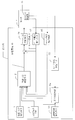
- Embodiment 1 of this invention It is a schematic block diagram which shows the structure of the electric power steering control apparatus in Embodiment 1 of this invention. It is the block diagram which showed the connection relationship between the motor of FIG. 1, and ECU. It is explanatory drawing which showed the output signal of the resolver detection part in Embodiment 1 of this invention with the Lissajous curve. It is explanatory drawing which shows the relationship between the radius of a Lissajous circle and the temperature of an output winding in Embodiment 1 of this invention. It is a flowchart of the abnormality determination means in Embodiment 1 of this invention. It is a flowchart of the target current setting in Embodiment 1 of this invention.
- FIG. Embodiment 1 of the present invention will be described in detail below with reference to the drawings.
- 1 is a block diagram for illustrating a configuration of an electric power steering control apparatus according to Embodiment 1 of the present invention.
- a motor 4 for assisting a driver's steering force and an electronic control unit (hereinafter referred to as an ECU) 5 for controlling the motor 4 are integrally configured.
- Steering torque detecting means 1 for detecting the steering force, motor current detecting means 37 for detecting the current 31 of the motor 4, and a current flowing through the motor 4 to assist the driver's steering force are calculated.
- Target current setting means 2 motor current control means 36, motor rotation angle detection means 35 for detecting the motor rotation angle and motor temperature detection means 32 for detecting the motor temperature based on signals from the resolver detection unit 13, and a thermistor, for example.
- the ambient temperature detection means 33 for detecting the temperature on the substrate of the ECU 5 from the detection value by the ECU 5, the motor temperature detection means 32 and the ambient temperature detection means 3 described above.
- the information obtained from, and a malfunction determination unit 34 for carrying out the abnormality determination of the ambient temperature detecting means 33.
- the motor target current setting means 2 calculates the target current in accordance with the detected torque from the steering torque detecting means 1, the output from the motor rotation angle detecting means 35, the vehicle speed detecting means 3, the motor current detecting means 37, and the like. A value obtained by limiting the target current by the ambient temperature detection unit 33 and the abnormality determination unit 34 is finally determined as the target current 30.
- the motor current control means 36 is a proportional / integral control means (PI) so that the deviation between the target current 30 output from the target current setting means 2 and the motor current 31 detected from the motor current detection means 37 becomes zero. Control) or proportional / integral / derivative control means (PID control) is used to calculate a motor drive signal to control the motor current 31.
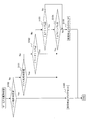
- a radius of a Lissajous circle, which will be described later, obtained from a signal output from the resolver detection unit 13 is calculated by the motor temperature detection means 32, and the motor temperature is detected accurately from the calculation result.
- the ambient temperature obtained by the ambient temperature detection means 33 can be used to accurately determine the abnormality of the ambient temperature detection means 33, and the optimum motor current 31 can be controlled at the time of abnormality determination. An example of the control method will be described in detail below.
- FIG. 2 is a block diagram showing in detail the connection relationship between the motor 4 and the ECU 5 shown in FIG.
- the resolver detection unit 13 includes a rotor (not shown) that rotates in synchronization with the motor 4 and a one-phase excitation winding to which an excitation signal from the ECU 5 is applied. And a stator for an output signal (not shown) having two-phase output windings for outputting a motor rotation angle detection signal.
- the output signal stator is arranged so that the phase of the output signal is shifted by 90 °.
- the ECU 5 and the resolver detection unit 13 include an excitation signal line 25 for applying an excitation signal to the excitation winding of the resolver detection unit 13 using a detection power source (not shown) connected to the ECU 5, and an output
- the two output signal lines 26 that transmit signals to the ECU 5 are connected to each other.
- the motor 4 is connected to three power lines 27 that supply a three-phase alternating current using a driving power source (not shown) connected to the ECU 5.
- the ECU 5 is connected to a vehicle-side ECU (not shown) and various sensors in addition to the detection power source and the driving power source.
- an excitation signal R which is a sine wave of, for example, 10 (kHz) and 5 (Vpp) is applied to the excitation winding of the resolver detection unit from the detection power source via the ECU 5.
- the excitation signal R is expressed as the following equation (1).
- E an excitation voltage
- ⁇ an angular velocity
- t time.
- An excitation current flows through the excitation winding by the excitation signal R, and a magnetic flux is generated in a gap portion between the excitation stator and the output signal rotor of the resolver detection unit.
- Scos K ⁇ E ⁇ sin ⁇ t ⁇ cos ⁇ (2)
- Ssin K ⁇ E ⁇ sin ⁇ t ⁇ sin ⁇ (3)
- K is the transformation ratio
- E is the excitation voltage
- ⁇ is the angular velocity
- t is the time
- ⁇ is the electrical angle
- Output signals Scos and Ssin are output to the ECU 5. Since the output signals Scos and Ssin are 90 ° out of phase, the motor rotation angle can be detected.
- the motor rotation angle detection means 35 provided in the ECU 5 detects the motor rotation angle ⁇ using the following equation (4).
- the motor temperature detecting means 32 simultaneously changes the values of the output signals Scos and Ssin to relative values from ⁇ 1 to 1, the horizontal axis is the relative value of the output signal Scos, and the vertical axis is the relative value of the output signal Ssin. Plot as. Since the output signals Scos and Ssin oscillate with each other, a circular Lissajous curve (hereinafter referred to as “Lissajous circle”) shown in FIG. 3 is obtained. The radius r of this Lissajous circle is expressed by the following equation (5).
- the output signal output from the output winding changes depending on the temperature T (hereinafter referred to as T) of the output winding. Therefore, the radius r of the Lissajous circle changes according to the temperature T of the output winding.
- FIG. 4 shows the relationship between the temperature T of the output winding and the radius r of the Lissajous circle.
- the motor temperature detection means 32 stores the characteristics shown in FIG. 4 in the ECU 5 in advance as a temperature characteristic table.
- the motor temperature detecting means 32 calculates the radius r of the Lissajous circle using the equation (5), and detects the temperature T of the output winding with reference to the temperature characteristic table.
- the temperature T of the output winding having temperature characteristics is detected by the motor temperature detecting means 32, so that the temperature of the motor 4 including the ambient temperature can be detected more accurately from the low temperature region to the high temperature region. Will be able to.
- the motor temperature detecting means 32 calculates the radius r of the Lissajous circle using the values of one output signal Scos and Ssin, but the values of the output signals Scos and Ssin are calculated for one electrical angle period. By sampling a plurality of ranges or the like and obtaining the radius r, the radius r can be calculated more accurately and quickly.
- the temperature detection means using the Lissajous circle has been described as an example.
- the temperature detection method using the temperature characteristics of the resolver detection unit is not particularly limited to this unless it departs from the gist of the present invention. is not.
- the ambient temperature detection means 33 for detecting the ambient temperature will be described.
- the ambient temperature detection means 33 is equipped with a component that directly detects the temperature, such as a thermistor, in the ECU 5 and detects the ambient temperature T1.
- the ECU 5 converts the resistance value that changes depending on the temperature of the thermistor into a voltage inside the ECU, converts the voltage value (hereinafter referred to as V1) to a temperature, and detects it as an ambient temperature T1 (hereinafter referred to as T1).
- the motor temperature and the ambient temperature are substantially the same. Even if there is a temperature difference between the temperatures T1 and T1 depending on the mounting position of the ECU 5 or the mounting position of the thermistor, the temperature difference between the motor temperature and the ambient temperature can be determined by taking into account the result of measurement in advance. Can be easily detected.
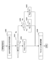
- FIG. 5 is a flowchart of the processing of the abnormality determination unit 34 that performs abnormality determination of the ambient temperature detection unit 33.
- it is determined from the voltage V1 whether or not the thermistor which is the ambient temperature detection means 33 is electrically grounded in step S100. If YES, the process proceeds to step S105.
- an abnormality determination flag F is set as an abnormality determination.
- step S100 the process proceeds to step S101, where it is determined whether the thermistor is electrically a power fault. If YES, the process proceeds to step S105, and if NO, the process proceeds to step S102.
- step S100 if it is determined in step S100 and step S101 that the electrical connection status is not abnormal by V1, the process proceeds to step S102, and determination is made in a region where abnormality cannot be determined by voltage V1 in steps S102 to S104.
- step S102 the temperatures T1 and T are compared to determine whether or not the temperature is equal to or higher than a predetermined value Tfail. If it is equal to or higher than Tfail, the determination is YES and the process proceeds to step S105, where the abnormality determination result F is stored. .
- the predetermined position Tfail is set in consideration of the difference between the detected values of T1 and T at the same ambient temperature.
- Tfail since the ambient temperature of the portion that generates heat cannot be reflected, it is necessary to set Tfail relatively large, in other words, to set a large margin in order to prevent erroneous determination.
- Tfail since the temperatures T1 and T are both detected values reflecting the ambient temperature, a margin due to the ambient temperature is not necessary, and Tfail can be set to a smaller value than in the prior art.
- the difference between the temperatures T and T1 should be small, but if the difference between T and T1 is large, it is determined that there is an abnormality due to abnormal thermistor output due to sticking or the like. It will be.
- the temperature T of the output winding reflects the ambient temperature in the same manner as the ambient temperature T1 and can be detected with high accuracy. Therefore, when the conventional motor current is used On the other hand, it can be said that the margin for erroneous determination of the determination value can be made smaller and the detectability is excellent.
- step S102 determines whether or not the change amount ⁇ T of the detected temperature T during the predetermined period t0 is within a predetermined value Tfail2. If it is determined YES, it is determined that the amount of change during t0 in the predetermined period is small, and the process proceeds to step S104.
- step S104 it is determined whether or not the change amount ⁇ T1 of the ambient temperature T1 during the predetermined period t0 is larger than the predetermined value Tfail3. If it determines with YES, it will progress to step S105 and will set the abnormality determination result F. FIG. When it is determined No, it is determined that the thermistor that is the ambient temperature detection means 33 is normal, the process proceeds to step S106, and the abnormality determination result F is cleared.
- the predetermined period t0 is a value in which, for example, the time when the power of the ECU 5 is turned on is set in the ECU so that the temperature of the heat generating part changes sufficiently, and the measurement timing of ⁇ T and ⁇ T1 is the same.
- the measurement timing and the measurement period of ⁇ T and ⁇ T1 are synchronized, and the measurement method of t0 does not need to be particularly concerned with this method as long as the period during which the temperature changes sufficiently is taken into consideration.
- Tfail2 and Tfail3 for example, the minimum values of ⁇ T and ⁇ T1 that can change during t0 are set in the ECU 5 in advance.
- step S103 determines that the amount of change ⁇ T1 in T1 during the predetermined period t0 is greater than the predetermined value even though the amount of change ⁇ T1 in T during the predetermined period t0 is small, clearly T and T1 It is determined that there is a difference in the detection results. Therefore, even if the difference between T1 and T that cannot be determined in step S102 is small, the ambient temperature detection means 33 is determined by determining in steps S103 and S104 that there is a difference in the values ⁇ T and ⁇ T1 of the constant period t0. Output abnormality can be determined.
- step S103 and step S104 may be omitted.
- step S102 when it is substantially necessary to make a determination in step S102, such as when it is necessary to set a relatively large value as Tfail, step S102 may be omitted and only the determinations in steps S103 and S104 may be performed. Absent.
- step S200 the motor target current setting unit 2 sets the basic target current determined according to the detected torque from the steering torque detecting unit 1 and the outputs from the motor rotation angle detecting unit 35 and the vehicle speed detecting unit 3. Processing to set.
- step S201 a determination is made to select an ambient temperature used for a target current limiting process described later.
- step S201 it is first determined whether or not the ambient temperature detection means 33 is abnormal, that is, whether or not the abnormality determination result F is set. If the abnormality determination result F is set, the process proceeds to step S202.
- step S202 the ambient temperature Tlimit used when the ambient temperature detection means 33 is abnormal for the target current limiting process is determined.
- Tlimit is the ambient temperature used to limit the motor current for overheating protection of the motor 4 and the ECU 5 in step S206, and the motor current is controlled in a direction in which the motor current is limited as Tlimit is higher, and thermally. It will be protected.
- the value of the ambient temperature T1 detected when the ambient temperature detection means 33 is normal is higher than the motor temperature T. Therefore, when the value of T1 is abnormal, the motor temperature T is lower than the actual temperature, so T ⁇ corresponding to the difference from the actual value is added.
- the temperature is controlled to be thermally safer as the ambient temperature is higher in step S206, so that the temperature is not lower than the actual temperature.
- the ambient temperature detection means 33 is normal and the ambient temperature T1 is equal to the motor temperature T or the motor temperature T is higher, it works in the safe direction without adding T ⁇ . Absent. Since the temperature correlation between T1 and T can be obtained in advance on a trial basis, whether or not T ⁇ needs to be set may be determined based on the correlation.
- step S203 the motor temperature T is compared with the ambient temperature T1, and if it is determined that T is higher, the process proceeds to step S204, and the motor temperature T is set to Tlimit, and the process proceeds to step S206. If it is determined in step S203 that T1 is higher, the process proceeds to step S205, the ambient temperature T1 is set in Tlimit, and the process proceeds to step S206. That is, in steps S203 to S205, Tlimit is set in a safer direction by comparing T and T1 and selecting a higher temperature.
- step S206 the motor current detection means is used by using the Tlimit set to the optimum value in both the normal state and the abnormal state. According to the input from 37, the motor current is limited so as to prevent overheating of the motor and controller due to motor overload.
- the electric power steering control apparatus generates an assist force for the turning operation of the steering handle when a current corresponding to the driving state of the vehicle is applied, and the resolver detection unit is
- the signal from the resolver detector has temperature characteristics due to its nature. That is, there is a correlation with the motor temperature itself that reflects not only the heat generation of the motor current but also the ambient temperature. It can be said that the ambient temperature between the motor and the ECU, which is a part that generates heat, is substantially equal to the motor temperature if the motor is adjacent to the ECU or if the motor and the ECU are integrated. Even if there is a slight temperature difference, it is easy to consider the temperature difference between the motor and the heat generating part on a trial basis. Therefore, according to the electric power steering control device of the first embodiment of the present invention, the ambient temperature can be detected with high accuracy by the motor temperature detection means based on the signal of the resolver detection unit.
- the ambient temperature detection means is compared with the detection temperature reflecting the ambient temperature by the temperature detection means based on the signal from the resolver detection unit.
- the margin for avoiding erroneous determination of the abnormality determination value of the detection means can be made as small as possible, and abnormality determination of the ambient temperature detection means can be performed with high accuracy.
- the temperature change time for estimating the temperature in other words, the temperature rises to some extent. I need time.
- the signal of the resolver detection unit of the first embodiment is a signal synchronized with the motor rotation speed, it is possible to detect the temperature in a very short time with almost no increase in temperature simply by operating the motor. it can. Therefore, the temperature can be detected more quickly than the conventional method, and the abnormality of the ambient temperature detecting means can be quickly determined. As a result, even if the ambient temperature detection means is already abnormal, the time until the abnormality determination is shortened, and it is possible to quickly limit the current so as to reduce the damage of the portion that generates heat due to the motor current.
- the motor temperature detection means based on the signal of the resolver detection unit has temperature characteristics and can detect the temperature quickly. Therefore, temperature detection is possible even in a low temperature region, which is difficult with the conventional method. Even in the low temperature range, it is possible to detect the motor temperature and determine the abnormality of the ambient temperature detecting means.
- the temperature is detected based on the signal from the resolver detection unit provided in the motor for the main purpose of detecting the motor rotation angle, it is already used for the abnormality determination of the ambient temperature detection means. Without adding one thermistor, the same effect as when adding the thermistor without increasing the cost can be obtained.
- the present invention can be applied to an electric power steering device for a vehicle provided with an electric motor that applies an assist force to a turning operation of a steering handle.
- 1 steering torque detection means 1 steering torque detection means, 2 target current setting means, 3 vehicle speed detection means, 4 motor, 5 ECU, 13 resolver detector, 25 excitation signal line, 26 output signal lines, 27 power lines, 32 motor temperature detecting means, 33 ambient temperature detection means, 34 abnormality determination means, 35 motor angle detection means, 36 motor current control means, 37 Motor current detection means.
Landscapes
- Engineering & Computer Science (AREA)
- Power Engineering (AREA)
- Chemical & Material Sciences (AREA)
- Combustion & Propulsion (AREA)
- Transportation (AREA)
- Mechanical Engineering (AREA)
- Power Steering Mechanism (AREA)
- Steering Control In Accordance With Driving Conditions (AREA)
Abstract
Description
これに対して特許文献1に開示される従来の技術では、発熱する部分の推定値は電動モータの電流のみからの推定温度値であり、その性質上、車両の雰囲気温度まで考慮できないため、実際の温度に対する誤差が生じ、その結果、温度検出手段が異常であることの判定値に比較的大きなマージンを持たせないと、誤検出の恐れがあるという問題がある。
この場合、例えば電動パワーステリングシステムが起動し温度検出を開始した時には、既にモータは高温状態であるにもかかわらず、温度検出手段が低い温度を示すような異常の場合には、温度検出手段が異常であるにもかかわらず、温度推定するまでは異常を検知できないという問題がある。
さらに、この問題を解消するために前述の周辺温度検出手段である例えばサーミスタを異常判定用にもう1個追加し、2個使うことも考えられるが、その場合はコストアップを招いてしまう。
以下、この発明の実施の形態1について、図面を参照して詳述する。
図1はこの発明の実施の形態1における電動パワーステアリング制御装置の構成を説明するためのブロック図である。
図1において、運転者の操舵力を補助するためのモータ4と、モータ4を制御するための電子制御ユニット(以下、ECUという)5は一体化して構成されており、ECU5は、運転者のステアリング操舵力を検出するための操舵トルク検出手段1と、モータ4の電流31を検出するためのモータ電流検出手段37と、運転者の操舵力を補助するためにモータ4に流す電流を演算する目標電流設定手段2と、モータ電流制御手段36と、レゾルバ検出部13の信号により、モータ回転角度を検出するモータ回転角度検出手段35およびモータ温度を検出する、モータ温度検出手段32と、たとえばサーミスタによる検出値からECU5の基板上の温度を検出する周囲温度検出手段33と、上述のモータ温度検出手段32と周囲温度検出手段33から得られた情報により、周囲温度検出手段33の異常判定を実施する異常判定手段34から構成されている。
以下にその制御方法の一例について詳述する。
図2は、図1に示したモータ4とECU5との接続関係を詳細に示したブロック図である。 図2において、レゾルバ検出部13は、モータ4に同期して回転する図示しない回転子と、ECU5からの励磁信号が印加される1相の励磁巻き線を有している図示しない励磁用の固定子と、モータ回転角度検出信号を出力するために2相の出力巻き線を有する図示しない出力信号用の固定子で構成されている。ここで出力信号用の固定子は、出力信号の位相が90°ずれるように配置されている事とする。
また、図2において、ECU5とレゾルバ検出部13とは、ECU5に接続された図示しない検出用電源を用いてレゾルバ検出部13の前記励磁巻線に励磁信号を印加する励磁信号線25と、出力信号をECU5に伝送する2本の出力信号線26とで互いに接続されている。
なお、ECU5には、上記の検出用電源および駆動用電源に加え、さらに図示しない車両側のECUや各種センサが接続されている。
まず、レゾルバ検出部の励磁巻線には、検出用電源から、ECU5を介して、例えば10(kHz)、5(Vpp)の正弦波である励磁信号Rが印加されている。
励磁信号Rは、次式(1)のように表される。
ここで、Eは励磁電圧、ωは角速度、tは時間。
励磁信号Rにより励磁巻線に励磁電流が流れ、レゾルバ検出部の励磁用固定子と出力信号用の回転子との空隙部分に磁束が発生する。
Ssin=K・E・sinωt・sinθ・・・(3)
ここで、Kは変圧比、Eは励磁電圧、ωは角速度、tは時間、θは電気角。
ECU5に設けられたモータ回転角度検出手段35は、次式(4)を用いて、モータ回転角度θを検出する。

モータ温度検出手段32は、図4に示した特性を温度特性テーブルとしてECU5に予め記憶している。
モータ温度検出手段32は、式(5)を用いてリサージュ円の半径rを算出し、温度特性テーブルを参照して出力巻線の温度Tを検出する。
この実施の形態1においては、周囲温度検出手段33は、例えばサーミスタのように直接的に温度を検出する部品をECU5に装着し、周囲温度T1を検出しているものとする。
ECU5は、サーミスタの温度により変化する抵抗値をECU内部で電圧変換し、その電圧値(以下V1とする)を温度変換し周囲温度T1(以下T1とする)として検出する。
図5において、ステップS100で周囲温度検出手段33であるサーミスタが電気的に地絡したか否かを電圧V1により判定し、YESであればステップS105へ進む。
ステップS105では、異常判定したとして異常判定フラグFをセットする。
従来の温度推定方法では、発熱する部分の雰囲気温度が反映できないため、異常誤判定させないためには、Tfailを比較的大きく、言い換えるとマージンを大きく設定する必要があったが、本実施の形態1では温度T1とTは両方とも雰囲気温度が反映された検出値のため、雰囲気温度によるマージンは必要がなくなりTfailは従来に比べ小さい値が設定可能となる。
つまりサーミスタの電気的な接続状況が正常であれば、本来温度TとT1の差は小さいはずであるにもかかわらず、TとT1差が大きければ固着などによるサーミスタの出力異常による異常と判定することになる。
YESと判断されれば所定期間のt0間の変化量が少ないと判断されることとなり、ステップS104へ進む。
また、Tfail2、Tfail3は例えばt0間に変化しうるΔTとΔT1の最低値をあらかじめECU5に設定しておく。
よって前述のステップS102で判断できないT1とTの差が小さい場合でも、一定期間t0の変化量ΔT、ΔT1の値に差があることをステップS103、S104で判定することにより、周囲温度検出手段33の出力異常を判定できることになる。
図6において、ステップS200で、モータ目標電流設定手段2は、操舵トルク検出手段1からの検出トルクおよびモータ回転角度検出手段35および車速検出手段3からの出力に従って決定される基本となる目標電流を設定する処理を行っている。
ステップS201では、まず周囲温度検出手段33が異常か否か、すなわち異常判定結果Fがセットされているか否かを判定している。異常判定結果FがセットされていればステップS202へ進む。
ここでTlimitは、ステップS206でモータ4やECU5の過熱保護のためモータ電流を制限するために使用される周囲温度であり、Tlimitが高いほどモータ電流は制限される方向に制御され、熱的に保護されることになる。
本実施の形態1では、周囲温度検出手段33が正常な場合に検出された周囲温度T1の値が、モータ温度Tより高い値であることを想定している。そのため、T1の値が異常な場合、モータ温度Tが実際の温度より低いこととなるため、実際値との差分相当のTαを加算している。これは前述の通り電流制限をする場合は、ステップS206で周囲温度が高いほど熱的に安全な方向に制御させているため、実際の温度より低い温度となることを防ぐためである。
周囲温度検出手段33が正常な場合の周囲温度T1とモータ温度Tが一致もしくは、モータ温度Tのほうが高い場合は、Tαを加算せずとも安全方向に働くため、その場合は特に加算する必要はない。尚T1とTについての温度の相関関係はあらかじめ試験的に得ることが出来るため、その相関関係により、Tαの設定要否は判断すればよい。
ステップS203でT1のほうが高いと判断されればステップS205へ進み、Tlimitには周囲温度T1が設定されステップS206へ進む。
つまり、ステップS203~S205では、TとT1を比較し高い温度を選択することにより、より安全な方向にTlimitを設定することになる。
発熱する部分であるモータとECUの周囲温度は、モータがECUと隣接していたり、モータとECUが一体型であれば、ほぼモータ温度と等しいといえる。また、多少温度差がある場合でも試験的にモータと発熱する部分の温度差を考慮することは容易である。
従って、本発明の実施の形態1の電動パワーステアリング制御装置によれば、レゾルバ検出部の信号をもとにしたモータ温度検出手段により、精度よく周囲温度を検出することができるので、発熱する部分の周囲温度検出手段が異常な場合、この周囲温度検出手段の検出温度と、レゾルバ検出部の信号をもとにした温度検出手段による雰囲気温度を反映した検出温度とを比較することで、周囲温度検出手段の異常判定値の誤判定回避のためのマージンを極力小さくすることができ、精度よく周囲温度検出手段の異常判定が可能となる。
これに対し、本実施の形態1のレゾルバ検出部の信号は、モータ回転数に同期した信号であるため、モータを動作させるだけでほとんど温度上昇を伴わないごく短時間で温度検出をすることができる。
従って、従来の方法よりすばやく温度検出ができ、周囲温度検出手段の異常もすばやく判定できることになる。その結果、すでに周囲温度検出手段が異常であっても異常判定までの時間が短くなり、モータ電流による発熱する部分のダメージをより少なくするよう迅速に電流制限をすることが可能となる。
4 モータ、5 ECU、13 レゾルバ検出部、25 励磁信号線、
26 出力信号線、27 電力線、32 モータ温度検出手段、
33 周囲温度検出手段、34 異常判定手段、
35 モータ角度検出手段、 36 モータ電流制御手段、
37 モータ電流検出手段。
Claims (6)
- 車両の運転状態に応じた電流が流されて操舵ハンドルの回動操作に対するアシスト力を発生し、且つレゾルバ検出部を有するモータを備えた車両の電動パワーステアリング制御装置において、
前記電流により発熱する部分の周囲温度を検出する周囲温度検出手段と、
前記モータのレゾルバ検出部の信号にもとづいて、温度特性を持った、前記発熱する部分の温度を推定するモータ温度検出手段と、
前記周囲温度検出手段による検出温度と前記モータ温度検出手段により検出された温度とを比較して、前記周囲温度検出手段が異常であることを判定する異常判定手段とを備えたことを特徴とする車両の電動パワーステアリング制御装置。 - 前記異常判定手段は、前記周囲温度検出手段により検出した温度と前記モータ温度検出手段により検出された温度とを比較して、両者の温度が所定値以上乖離しているときに前記周囲温度検出手段が異常であると判断するようにしたことを特徴とする請求項1に記載の電動パワーステアリング制御装置。
- 前記異常判定手段は、前記周囲温度検出手段により検出した温度が所定温度以上変化しておらず、前記モータ温度検出手段により検出された温度が所定温度以上変化しているときに、前記周囲温度検出手段が異常であると判断するようにしたことを特徴とする請求項1に記載の電動パワーステアリング制御装置。
- 前記異常判定手段は、前記周囲温度検出手段により検出した温度および前記モータ温度検出手段により検出された温度の、所定時間当たりの温度変化量で前記周囲温度検出手段が異常であると判断するようにしたことを特徴とする請求項3に記載の電動パワーステアリング制御装置。
- 前記異常判定手段が、前記周囲温度検出手段が異常であると判定した場合に、前記モータ温度検出手段により検出した温度により前記モータの電流制限をすることを特徴とする請求項1~請求項4のいずれか1項に記載の電動パワーステアリング制御装置。
- 前記異常判定手段が、前記周囲温度検出手段が異常ではないと判定した場合には、前記周囲温度検出手段により検出した温度と前記モータ温度検出手段により検出した温度の高いほうの温度に基づき、前記モータの電流制限をすることを特徴とする請求項1~請求項4のいずれか1項に記載の電動パワーステアリング制御装置。
Priority Applications (5)
| Application Number | Priority Date | Filing Date | Title |
|---|---|---|---|
| CN201180069676.0A CN103442968B (zh) | 2011-04-21 | 2011-04-21 | 电动助力转向控制装置 |
| PCT/JP2011/059830 WO2012144047A1 (ja) | 2011-04-21 | 2011-04-21 | 電動パワーステアリング制御装置 |
| JP2013510790A JPWO2012144047A1 (ja) | 2011-04-21 | 2011-04-21 | 電動パワーステアリング制御装置 |
| EP11863837.8A EP2700562B1 (en) | 2011-04-21 | 2011-04-21 | Electric power steering control device |
| US13/980,407 US9899952B2 (en) | 2011-04-21 | 2011-04-21 | Electric power steering control device |
Applications Claiming Priority (1)
| Application Number | Priority Date | Filing Date | Title |
|---|---|---|---|
| PCT/JP2011/059830 WO2012144047A1 (ja) | 2011-04-21 | 2011-04-21 | 電動パワーステアリング制御装置 |
Publications (1)
| Publication Number | Publication Date |
|---|---|
| WO2012144047A1 true WO2012144047A1 (ja) | 2012-10-26 |
Family
ID=47041196
Family Applications (1)
| Application Number | Title | Priority Date | Filing Date |
|---|---|---|---|
| PCT/JP2011/059830 Ceased WO2012144047A1 (ja) | 2011-04-21 | 2011-04-21 | 電動パワーステアリング制御装置 |
Country Status (5)
| Country | Link |
|---|---|
| US (1) | US9899952B2 (ja) |
| EP (1) | EP2700562B1 (ja) |
| JP (1) | JPWO2012144047A1 (ja) |
| CN (1) | CN103442968B (ja) |
| WO (1) | WO2012144047A1 (ja) |
Families Citing this family (8)
| Publication number | Priority date | Publication date | Assignee | Title |
|---|---|---|---|---|
| JP2014169061A (ja) * | 2013-03-05 | 2014-09-18 | Jtekt Corp | 電動パワーステアリング装置 |
| US10025329B2 (en) * | 2013-08-21 | 2018-07-17 | Google Technology Holdings LLC | Method and apparatus for adjusting portable electronic device operation based on ambient temperature |
| JP5898244B2 (ja) * | 2014-01-20 | 2016-04-06 | 本田技研工業株式会社 | 車両用操舵装置 |
| JP2015166199A (ja) * | 2014-03-03 | 2015-09-24 | 本田技研工業株式会社 | 車両用操舵装置 |
| JP6131214B2 (ja) * | 2014-05-08 | 2017-05-17 | 本田技研工業株式会社 | 車両用操舵装置 |
| US10259491B2 (en) * | 2014-06-13 | 2019-04-16 | Nsk Ltd. | Motor control apparatus and electric power steering apparatus provided the same |
| JP6231523B2 (ja) * | 2015-07-09 | 2017-11-15 | ファナック株式会社 | 巻線の温度を推定するモータ制御装置、および機械の許容デューティサイクル時間算出方法 |
| KR102618388B1 (ko) * | 2018-03-27 | 2023-12-27 | 히다치 아스테모 가부시키가이샤 | 전동 모터의 제어 장치 및 브레이크 장치 |
Citations (9)
| Publication number | Priority date | Publication date | Assignee | Title |
|---|---|---|---|---|
| JP2001130432A (ja) | 1999-11-02 | 2001-05-15 | Toyota Motor Corp | 車両の電動パワーステアリング装置 |
| JP2002240733A (ja) * | 2001-02-15 | 2002-08-28 | Nsk Ltd | 電動パワーステアリング装置の制御装置 |
| JP2003315162A (ja) * | 2002-04-25 | 2003-11-06 | Toyoda Mach Works Ltd | レゾルバを用いた温度検出方法、アクチュエータの温度検出方法および電気式動力舵取装置 |
| JP2004082757A (ja) * | 2002-08-22 | 2004-03-18 | Honda Motor Co Ltd | 電動パワーステアリング装置の制御方法 |
| JP2004090676A (ja) * | 2002-08-29 | 2004-03-25 | Nsk Ltd | 電動パワーステアリング装置 |
| JP2004268671A (ja) * | 2003-03-06 | 2004-09-30 | Honda Motor Co Ltd | 電動パワーステアリング装置の出力制限方法 |
| JP2006044437A (ja) * | 2004-08-04 | 2006-02-16 | Nsk Ltd | 電動パワーステアリング装置 |
| JP2006214969A (ja) * | 2005-02-07 | 2006-08-17 | Mitsubishi Electric Corp | レゾルバ |
| JP2010030469A (ja) * | 2008-07-29 | 2010-02-12 | Jtekt Corp | 舵角検出装置 |
Family Cites Families (23)
| Publication number | Priority date | Publication date | Assignee | Title |
|---|---|---|---|---|
| US3921220A (en) * | 1974-07-15 | 1975-11-18 | Odetics Inc | Apparatus for automatic high speed positioning of magnetic recording tape by sensing reel revolutions from tape beginning |
| JPS6369477A (ja) * | 1986-09-10 | 1988-03-29 | Yaskawa Electric Mfg Co Ltd | 温度検出機能付電動機制御装置 |
| JP3231887B2 (ja) * | 1993-03-31 | 2001-11-26 | 能美防災株式会社 | 熱感知器 |
| JP2001177905A (ja) * | 1999-12-10 | 2001-06-29 | Honda Motor Co Ltd | 電気自動車の制御装置 |
| JP4391719B2 (ja) * | 2002-03-20 | 2009-12-24 | トヨタ自動車株式会社 | モータ温度推定装置およびモータ制御装置 |
| JP4070489B2 (ja) * | 2002-03-27 | 2008-04-02 | 株式会社ジェイテクト | 電気式動力舵取装置 |
| JP4389208B2 (ja) * | 2004-02-12 | 2009-12-24 | 株式会社デンソー | 電動パワーステアリング制御装置 |
| JP4182082B2 (ja) * | 2005-04-18 | 2008-11-19 | ファナック株式会社 | 工作機械 |
| JP2007137535A (ja) * | 2005-11-15 | 2007-06-07 | Ricoh Co Ltd | ベルト駆動制御装置及びこれを備えた画像形成装置 |
| JP4979352B2 (ja) * | 2006-02-28 | 2012-07-18 | 日立オートモティブシステムズ株式会社 | レゾルバ/デジタル変換器及び該レゾルバ/デジタル変換器を用いた制御システム |
| EP2026458A1 (en) * | 2006-05-31 | 2009-02-18 | NSK Ltd. | Electric power steering device |
| JP4879657B2 (ja) * | 2006-05-31 | 2012-02-22 | 本田技研工業株式会社 | 電動機の制御装置 |
| JP4490401B2 (ja) * | 2006-08-10 | 2010-06-23 | 三菱電機株式会社 | 車両用操舵装置 |
| JP2008049968A (ja) * | 2006-08-28 | 2008-03-06 | Hitachi Ltd | パワーステアリング装置 |
| JP4964536B2 (ja) * | 2006-08-31 | 2012-07-04 | 矢崎総業株式会社 | モータ異常検出装置及び方法 |
| JP5336042B2 (ja) * | 2006-12-18 | 2013-11-06 | オークマ株式会社 | 工作機械における温度センサの異常検知方法 |
| JP2008230540A (ja) * | 2007-03-23 | 2008-10-02 | Showa Corp | 電動パワーステアリング装置 |
| US7839108B2 (en) * | 2008-01-24 | 2010-11-23 | Gm Global Technology Operations, Inc. | Electric motor stator winding temperature estimation |
| JP5228578B2 (ja) * | 2008-03-31 | 2013-07-03 | 株式会社ジェイテクト | モータ制御装置および電動パワーステアリング装置 |
| JP2010048760A (ja) * | 2008-08-25 | 2010-03-04 | Jtekt Corp | レゾルバの異常検出装置および電気式動力舵取装置 |
| DE102009029406A1 (de) * | 2009-09-14 | 2011-03-17 | Zf Lenksysteme Gmbh | Verfahren und Vorrichtung zur Temperatur-Überwachung in einem Steuergerät einer elektrischen Hilfskraftlenkung |
| JP5269748B2 (ja) * | 2009-11-05 | 2013-08-21 | 本田技研工業株式会社 | 過熱保護装置 |
| JP2012165564A (ja) * | 2011-02-07 | 2012-08-30 | Toyota Motor Corp | 車両の異常診断装置および車両の異常診断方法 |
-
2011
- 2011-04-21 EP EP11863837.8A patent/EP2700562B1/en not_active Not-in-force
- 2011-04-21 CN CN201180069676.0A patent/CN103442968B/zh not_active Expired - Fee Related
- 2011-04-21 US US13/980,407 patent/US9899952B2/en not_active Expired - Fee Related
- 2011-04-21 WO PCT/JP2011/059830 patent/WO2012144047A1/ja not_active Ceased
- 2011-04-21 JP JP2013510790A patent/JPWO2012144047A1/ja active Pending
Patent Citations (9)
| Publication number | Priority date | Publication date | Assignee | Title |
|---|---|---|---|---|
| JP2001130432A (ja) | 1999-11-02 | 2001-05-15 | Toyota Motor Corp | 車両の電動パワーステアリング装置 |
| JP2002240733A (ja) * | 2001-02-15 | 2002-08-28 | Nsk Ltd | 電動パワーステアリング装置の制御装置 |
| JP2003315162A (ja) * | 2002-04-25 | 2003-11-06 | Toyoda Mach Works Ltd | レゾルバを用いた温度検出方法、アクチュエータの温度検出方法および電気式動力舵取装置 |
| JP2004082757A (ja) * | 2002-08-22 | 2004-03-18 | Honda Motor Co Ltd | 電動パワーステアリング装置の制御方法 |
| JP2004090676A (ja) * | 2002-08-29 | 2004-03-25 | Nsk Ltd | 電動パワーステアリング装置 |
| JP2004268671A (ja) * | 2003-03-06 | 2004-09-30 | Honda Motor Co Ltd | 電動パワーステアリング装置の出力制限方法 |
| JP2006044437A (ja) * | 2004-08-04 | 2006-02-16 | Nsk Ltd | 電動パワーステアリング装置 |
| JP2006214969A (ja) * | 2005-02-07 | 2006-08-17 | Mitsubishi Electric Corp | レゾルバ |
| JP2010030469A (ja) * | 2008-07-29 | 2010-02-12 | Jtekt Corp | 舵角検出装置 |
Non-Patent Citations (1)
| Title |
|---|
| See also references of EP2700562A4 * |
Also Published As
| Publication number | Publication date |
|---|---|
| US20130285587A1 (en) | 2013-10-31 |
| EP2700562A1 (en) | 2014-02-26 |
| EP2700562B1 (en) | 2016-07-13 |
| CN103442968A (zh) | 2013-12-11 |
| US9899952B2 (en) | 2018-02-20 |
| EP2700562A4 (en) | 2015-07-08 |
| CN103442968B (zh) | 2016-10-19 |
| JPWO2012144047A1 (ja) | 2014-07-28 |
Similar Documents
| Publication | Publication Date | Title |
|---|---|---|
| WO2012144047A1 (ja) | 電動パワーステアリング制御装置 | |
| JP5942337B2 (ja) | 車両用操舵装置 | |
| CN109756171B (zh) | 马达控制系统中的容错电流测量 | |
| JP6056482B2 (ja) | 回転角センサの異常検出装置 | |
| US8901863B2 (en) | Motor control device | |
| EP2472716A1 (en) | Anomaly detection device for a permanent magnet synchronous electric motor | |
| US9369079B2 (en) | Method and device for monitoring a torque of an electric motor | |
| CN110620540B (zh) | 永磁同步马达驱动器的参数学习 | |
| JP6556343B2 (ja) | 角度検出装置および電動パワーステアリングの制御装置 | |
| CN111200384B (zh) | 电流感测故障下永磁同步马达驱动的前馈控制方法及系统 | |
| US10972032B2 (en) | Method and apparatus for detecting failure of current sensor of motor | |
| US7065437B2 (en) | Current limit for an electric machine | |
| EP2878514B1 (en) | Method and apparatus for detecting motor error of motor driven power steering | |
| JP2007315994A (ja) | 回転電機の温度変化検知方法およびその装置 | |
| JP2013127411A (ja) | モータロック発生時のスイッチング素子温度の計算装置 | |
| JP2009131069A (ja) | モータ制御装置 | |
| JP2019182233A (ja) | 操舵制御装置 | |
| JP3838499B2 (ja) | アクチュエータの温度検出方法および電気式動力舵取装置 | |
| JP5699972B2 (ja) | ツインレゾルバ式トルクセンサ及び電動パワーアシスト装置 | |
| KR101348569B1 (ko) | 전동 파워스티어링 장치 및 그의 과열방지방법 | |
| KR20160022923A (ko) | 전기 모터의 부정확한 각도 위치를 검출하는 방법 | |
| KR101597440B1 (ko) | 레졸버 옵셋 보정 방법 | |
| JP2006094669A (ja) | 電動車の駆動制御装置 | |
| JP5975143B2 (ja) | 車両用操舵装置 | |
| JP2011024337A (ja) | 永久磁石同期電動機の制御装置 |
Legal Events
| Date | Code | Title | Description |
|---|---|---|---|
| 121 | Ep: the epo has been informed by wipo that ep was designated in this application |
Ref document number: 11863837 Country of ref document: EP Kind code of ref document: A1 |
|
| ENP | Entry into the national phase |
Ref document number: 2013510790 Country of ref document: JP Kind code of ref document: A |
|
| WWE | Wipo information: entry into national phase |
Ref document number: 13980407 Country of ref document: US |
|
| REEP | Request for entry into the european phase |
Ref document number: 2011863837 Country of ref document: EP |
|
| WWE | Wipo information: entry into national phase |
Ref document number: 2011863837 Country of ref document: EP |
|
| NENP | Non-entry into the national phase |
Ref country code: DE |