WO2012144072A1 - Raccord d'éléments et unité de buse de pulvérisation l'utilisant - Google Patents
Raccord d'éléments et unité de buse de pulvérisation l'utilisant Download PDFInfo
- Publication number
- WO2012144072A1 WO2012144072A1 PCT/JP2011/059951 JP2011059951W WO2012144072A1 WO 2012144072 A1 WO2012144072 A1 WO 2012144072A1 JP 2011059951 W JP2011059951 W JP 2011059951W WO 2012144072 A1 WO2012144072 A1 WO 2012144072A1
- Authority
- WO
- WIPO (PCT)
- Prior art keywords
- elbow
- union nut
- nozzle
- lock
- nozzle holder
- Prior art date
- Legal status (The legal status is an assumption and is not a legal conclusion. Google has not performed a legal analysis and makes no representation as to the accuracy of the status listed.)
- Ceased
Links
Images




Classifications
-
- F—MECHANICAL ENGINEERING; LIGHTING; HEATING; WEAPONS; BLASTING
- F16—ENGINEERING ELEMENTS AND UNITS; GENERAL MEASURES FOR PRODUCING AND MAINTAINING EFFECTIVE FUNCTIONING OF MACHINES OR INSTALLATIONS; THERMAL INSULATION IN GENERAL
- F16L—PIPES; JOINTS OR FITTINGS FOR PIPES; SUPPORTS FOR PIPES, CABLES OR PROTECTIVE TUBING; MEANS FOR THERMAL INSULATION IN GENERAL
- F16L27/00—Adjustable joints; Joints allowing movement
- F16L27/08—Adjustable joints; Joints allowing movement allowing adjustment or movement only about the axis of one pipe
-
- B—PERFORMING OPERATIONS; TRANSPORTING
- B05—SPRAYING OR ATOMISING IN GENERAL; APPLYING FLUENT MATERIALS TO SURFACES, IN GENERAL
- B05B—SPRAYING APPARATUS; ATOMISING APPARATUS; NOZZLES
- B05B15/00—Details of spraying plant or spraying apparatus not otherwise provided for; Accessories
- B05B15/60—Arrangements for mounting, supporting or holding spraying apparatus
- B05B15/65—Mounting arrangements for fluid connection of the spraying apparatus or its outlets to flow conduits
- B05B15/652—Mounting arrangements for fluid connection of the spraying apparatus or its outlets to flow conduits whereby the jet can be oriented
-
- B—PERFORMING OPERATIONS; TRANSPORTING
- B05—SPRAYING OR ATOMISING IN GENERAL; APPLYING FLUENT MATERIALS TO SURFACES, IN GENERAL
- B05B—SPRAYING APPARATUS; ATOMISING APPARATUS; NOZZLES
- B05B15/00—Details of spraying plant or spraying apparatus not otherwise provided for; Accessories
- B05B15/60—Arrangements for mounting, supporting or holding spraying apparatus
- B05B15/65—Mounting arrangements for fluid connection of the spraying apparatus or its outlets to flow conduits
-
- F—MECHANICAL ENGINEERING; LIGHTING; HEATING; WEAPONS; BLASTING
- F16—ENGINEERING ELEMENTS AND UNITS; GENERAL MEASURES FOR PRODUCING AND MAINTAINING EFFECTIVE FUNCTIONING OF MACHINES OR INSTALLATIONS; THERMAL INSULATION IN GENERAL
- F16L—PIPES; JOINTS OR FITTINGS FOR PIPES; SUPPORTS FOR PIPES, CABLES OR PROTECTIVE TUBING; MEANS FOR THERMAL INSULATION IN GENERAL
- F16L19/00—Joints in which sealing surfaces are pressed together by means of a member, e.g. a swivel nut, screwed on, or into, one of the joint parts
- F16L19/005—Joints in which sealing surfaces are pressed together by means of a member, e.g. a swivel nut, screwed on, or into, one of the joint parts comprising locking means for the threaded member
-
- F—MECHANICAL ENGINEERING; LIGHTING; HEATING; WEAPONS; BLASTING
- F16—ENGINEERING ELEMENTS AND UNITS; GENERAL MEASURES FOR PRODUCING AND MAINTAINING EFFECTIVE FUNCTIONING OF MACHINES OR INSTALLATIONS; THERMAL INSULATION IN GENERAL
- F16L—PIPES; JOINTS OR FITTINGS FOR PIPES; SUPPORTS FOR PIPES, CABLES OR PROTECTIVE TUBING; MEANS FOR THERMAL INSULATION IN GENERAL
- F16L19/00—Joints in which sealing surfaces are pressed together by means of a member, e.g. a swivel nut, screwed on, or into, one of the joint parts
- F16L19/02—Pipe ends provided with collars or flanges, integral with the pipe or not, pressed together by a screwed member
-
- B—PERFORMING OPERATIONS; TRANSPORTING
- B05—SPRAYING OR ATOMISING IN GENERAL; APPLYING FLUENT MATERIALS TO SURFACES, IN GENERAL
- B05B—SPRAYING APPARATUS; ATOMISING APPARATUS; NOZZLES
- B05B1/00—Nozzles, spray heads or other outlets, with or without auxiliary devices such as valves, heating means
- B05B1/14—Nozzles, spray heads or other outlets, with or without auxiliary devices such as valves, heating means with multiple outlet openings; with strainers in or outside the outlet opening
-
- F—MECHANICAL ENGINEERING; LIGHTING; HEATING; WEAPONS; BLASTING
- F16—ENGINEERING ELEMENTS AND UNITS; GENERAL MEASURES FOR PRODUCING AND MAINTAINING EFFECTIVE FUNCTIONING OF MACHINES OR INSTALLATIONS; THERMAL INSULATION IN GENERAL
- F16L—PIPES; JOINTS OR FITTINGS FOR PIPES; SUPPORTS FOR PIPES, CABLES OR PROTECTIVE TUBING; MEANS FOR THERMAL INSULATION IN GENERAL
- F16L27/00—Adjustable joints; Joints allowing movement
- F16L27/08—Adjustable joints; Joints allowing movement allowing adjustment or movement only about the axis of one pipe
- F16L27/087—Joints with radial fluid passages
- F16L27/093—Joints with radial fluid passages of the "banjo" type, i.e. pivoting right-angle couplings
Definitions
- the present invention relates to a member joint for connecting two members so that relative rotation is allowed, and a spray nozzle unit in which a nozzle head and a nozzle holder are connected so as to be relatively rotatable.
- the member coupling of this invention points out both the pipe coupling and shaft coupling which use a union nut.
- Patent Document 1 As conventional examples of pipe joints, there are those shown in Patent Documents 1 and 2 below.
- the pipe joint of Patent Document 1 connects the rear pipe and the front pipe by holding a sleeve around the outer circumference of the front pipe and fastening it with a cover (which corresponds to a union nut) that is screwed to the main body. Like to do. Further, the cover body is fixed to the main body with a connecting pin to prevent the cover body from loosening.
- an adjustment joint is rotatably attached to the outer periphery of the tip via a ball, and a nozzle tip is attached to the tip of the adjustment joint using a union nut (cap nut). Because of such a structure, the union nut does not loosen even if the pipe joint and the adjustment joint rotate relative to each other.
- a container stopper loosening prevention structure that can be used as a measure against union nut loosening is disclosed in Patent Document 3 below.
- ratchet teeth that lock each other on the outer periphery of the container neck and the inner periphery of the container cap are provided, and when the cap is rotated in the closing direction, the cap side teeth move on the leading surface of the neck side teeth.
- the cap side teeth move on the neck side teeth trailing surface and get over the neck side teeth.
- One of the spray nozzle units currently under development by the present applicant is, for example, the one shown in FIG. 7, and in this product, it is necessary to prevent the union nut from loosening.
- nozzle head 13 held by the nozzle holder 11.
- the nozzle head 13 includes a total of four sets of pipe joints 30, each having two union nuts 3.
- the union nut 3 of one pipe joint 30 on one side is rotatably mounted on the outer periphery of one end of the first elbow 15 and screwed into the nozzle holder 11. Further, the union nut 3 of the other pipe joint 30 on one side is rotatably mounted on the outer periphery on one end side of the second elbow 16 and is screwed into the first elbow 15.
- the union nut 3 to be screwed into the nozzle holder 11 tightens the flange 6 provided on the outer periphery on the one end side of the first elbow 15.
- the other union nut 3 also tightens the flange 6 provided on the outer periphery of the second elbow 16 so that the first elbow 15 is connected to the nozzle holder 11.
- a second elbow 16 is connected.
- first elbow 15 is rotated by a predetermined angle with respect to the nozzle holder 11, and further, the second elbow 16 is rotated by a predetermined angle with respect to the first elbow 15.
- the rotation of the first elbow 15 and the second elbow 16 in the illustrated spray nozzle unit opens and closes the valve 14 disposed inside the pipe joint 30 and changes the position and orientation of the nozzle 12 fixed to the second elbow 16. If the valve is opened and closed and the position and orientation of the nozzle are switched by this method, the structure of the valve and the structure of relative rotation can be simplified.
- the flange 6 formed on the first elbow 15 or the second elbow 16 is fastened with the union nut 3, and strong friction is generated between the flange 6 and the pipe holder 30.
- the union nut 3 rotates (co-rotates) together and loosens.
- the second elbow 16 is rotated with respect to the first elbow 15.
- Patent Document 3 requires that the cap-side teeth get over the neck-side teeth by the force that rotates the cap in the loosening direction. It is difficult to ensure high reliability in prevention. In addition, there is a concern that the cap-side teeth and the neck-side teeth may be worn or crushed by rubbing each other, and there is a concern about durability.
- This invention relates to a member joint (a pipe joint or a shaft joint) in which a large force is unavoidably transmitted to a union nut connected to both members when the two members are relatively rotated.
- the challenge is to prevent the nut from rotating together without complicating the fixing and releasing of the nut, and without increasing the size and durability of the connection. Yes.
- a first member provided with a male screw on the outer periphery on the connection end side
- a second member provided with a flange on the outer periphery on the connection end side
- an outer periphery of the second member A union nut that is rotatably mounted and is screwed into the male screw, and the flange is sandwiched between the first member or another member held by the first member with the union nut, and
- a protrusion having a leading surface and a trailing surface inclined in opposite directions is provided on the outer periphery of the first member near the male screw forming portion, and the union nut is opened.
- a lock ring having an inner diameter larger than the outer diameter of the projection forming portion of the first member is rotatably attached to the tip portion, and the protrusion is formed on the inner periphery of the lock ring when the lock ring rotates.
- the lock ring is made of high-strength resin, preferably polyacetal called engineering plastic.
- the union nut can be formed of metal or resin.
- a plurality of protrusions, lock claws, and holding pieces are provided at a constant pitch in the circumferential direction, the number of the lock claws and the holding pieces is larger than the number of the protrusions, and the holding pieces are allowed to play between the lock claws. It is preferable to arrange in a fitted state, and the inclination angle of the trailing surface is larger than the inclination angle of the leading surface, and the lock claw is in a direction parallel to the trailing surface at a position in contact with the trailing surface. It is also preferable to incline it.
- This member joint can be provided as a pipe joint, and the first member and the second member (both pipes) can be connected by a union nut. Moreover, it can provide as a shaft coupling and can connect a 1st member and a 2nd member (each is a solid or hollow shaft) with a union nut.
- This invention also provides a spray nozzle unit in which the reliability of the connection of the nozzle head to the nozzle holder is enhanced using the above-described member joint.
- the spray nozzle unit includes a nozzle holder having an internal flow path, a nozzle head having a nozzle for ejecting liquid at the tip, a pipe joint that connects the nozzle head to the nozzle holder, and a connection between the nozzle holder and the nozzle head.
- the above-described member joint of the present invention is employed as the pipe joint.
- the union nut of the member joint is screwed into the male screw provided on the outer periphery of the end of the nozzle holder, and the flange provided on the end of the nozzle head on the connection side includes the union nut and the nozzle holder or the A projection having a leading surface and a trailing surface of the member joint sandwiched between members held by the nozzle holder is provided on the outer periphery of the nozzle holder in proximity to the male screw, and a union nut of the member joint
- the lock claw provided on the lock ring of the member joint is configured to be sandwiched between the clamping piece provided on the union nut and the trailing surface of the projection when the nut rotates alone in the loosening direction. .
- the spray nozzle unit includes a first elbow connected to the nozzle holder and a second elbow connected to the first elbow.
- the nozzle head includes a connection of the first elbow to the nozzle holder, and the first elbow.
- the connection of the second elbow to the elbow may be made using the member joint of the present invention described above.
- the valve joints are incorporated into the connecting portions of the respective member joints, that is, the connecting portion between the nozzle holder and the first elbow and the connecting portion between the first elbow and the second elbow, and the relative rotation between the nozzle holder and the first elbow, The first elbow and the second elbow rotate relative to each other so that the valve is opened and closed and the position and orientation of the nozzle provided on the second elbow are changed.
- the problem of loosening due to the joint rotation of the union nut is solved at both of the connection portions of the second elbow to the first elbow.
- the union nut when the union nut is rotated in the tightening direction, the lock claw is pushed by the clamping piece, the lock ring follows and rotates, and the lock claw is a protrusion (leading surface) provided on the outer periphery of the first member. ) To be elastically deformed and get over the protrusion. Therefore, the union nut can be tightened without limitation.
- the member joint of the present invention can prevent the union nut from rotating in the loosening direction without using a pin, and the fixing and releasing of the nut are not complicated.
- the lock ring may be a small part that fits on the outer periphery of the end of the union nut, and does not increase the size and complexity of the connecting part.
- the lock claw of the lock ring can be elastically deformed, and the lock claw escapes while elastically deforming and gets over the projection, so that the lock claw and the projection are hardly worn or crushed, and the durability is sufficiently secured.
- the union nut is prevented from loosening at a plurality of locations, and the reliability of the prevention of looseness is enhanced.
- the load of the lock claw and the clamping piece is dispersed, and the durability is further increased.
- the inclination angle of the trailing surface of the protrusion is made larger than the inclination angle of the leading surface, and the lock claw is inclined in a direction parallel to the trailing surface at a position in contact with the trailing surface. Further, it is possible to increase the clamping stability of the locking claw by the trailing surface and the clamping piece while keeping the rotation resistance of the locking ring low.
- the spray nozzle unit of the present invention does not loosen the union nut connecting the nozzle head and the nozzle holder. Therefore, it is possible to simplify the structure of the valve and relative rotation by opening and closing the valve and switching the position and orientation of the nozzle by a method in which the nozzle head and the nozzle holder are relatively rotated.
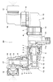
- Sectional drawing which shows an example of the member coupling of this invention 1 is an exploded perspective view of the member joint of FIG. (A), (b) is an operation explanatory view at the time of tightening the union nut, (c) is an operation explanatory view of the union nut loosening prevention, (d) is an operation explanatory view of the union nut loosening prevention release.
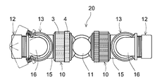
- Partially broken front view showing an example of the spray nozzle unit of the present invention Plan view of the spray nozzle unit of FIG. Side view of the spray nozzle unit of FIG. Partially broken front view showing spray nozzle unit before improvement
- the illustrated member joint 10 is configured as a pipe joint, and includes a first member 1 and a second member 2, a union nut 3, and a lock ring 4. All of these members are made by molding using a high-strength resin (for example, polyacetal) as a material.
- a high-strength resin for example, polyacetal
- the first member 1 and the second member 2 are pipes to be connected.
- the first member 1 and the second member 2 are connected by a union nut 3.
- a male screw 5 is provided on the outer periphery on the connection end side of the first member 1, and the union nut 3 is screwed to the male screw 5.
- the union nut 3 is mounted on the outer periphery of the second member 2, and the flange 6 provided on the outer periphery on the connection end side of the second member 2 is sandwiched between the opposing portion by the end wall 3 a.
- the flange 6 is sandwiched between the end wall 3 a of the union nut 3 and the connection end of the first member 1, but another member held by the first member 1 is provided in the connection portion. In this case, the flange 6 may be sandwiched between the other member and the end wall 3a.
- a plurality of projections 7 having a leading surface 7a and a trailing surface 7b inclined in opposite directions are provided at regular intervals in the circumferential direction on the outer periphery in the vicinity of the male screw forming portion on the connection end side of the first member 1 (four in the drawing are four). ) Is provided.
- the leading surface 7a of the projection 7 has a small inclination angle (rising angle from the outer peripheral surface of the first member), and the trailing surface 7b has a larger inclination angle than the inclination angle of the leading surface 7a (the member joint 10 shown in the figure is The inclination angle of the leading surface 7a is about 20 °, while the inclination angle of the trailing surface 7b is about 45 °).
- the union nut 3 has a clamping piece 8 protruding in the axial direction at the tip (the side opposite to the side having the end wall 3a).
- the number of the clamping pieces 8 is the same as the number of lock claws 9 of the lock ring, which will be described later, at a constant pitch in the circumferential direction, and each clamping piece 8 is arranged in a loosely fitted state between the lock claws 9 as shown in FIG. Is done.
- the lock ring 4 has an inner diameter that is larger than the outer diameter of the projection 7 forming portion of the first member 1, and the lock ring 4 can be rotated to the outer periphery of the tip small-diameter portion 3 b opened by the union nut 3. Is attached.
- the lock ring 4 is connected to the union nut 3 by inserting a minute convex portion 4 a provided on the inner peripheral surface into an annular groove 3 c provided on the outer periphery of the tip small-diameter portion 3 b of the union nut 3.
- a large number of lock claws 9 extending inward are provided on the inner periphery of the lock ring 4 at a constant pitch in the circumferential direction.
- the lock claw 9 is elastically deformable and is inclined in a preferred direction, that is, in a direction parallel to the trailing surface 7b at a position in contact with the trailing surface 7b of the protrusion 7 ⁇ FIG. , (D) reference ⁇ .
- the tip (free end) of the lock claw 9 is aligned on a circle having the same diameter as the outer diameter of the protrusion-free portion of the first member 1. Accordingly, the lock claw 9 comes into sliding contact with the protrusion 7 when passing through the position of the protrusion 7.
- the lock ring 4 When the union nut 3 tries to rotate in the loosening direction alone, the lock ring 4 receives the clamping piece 8 with the lock claw 9 and prevents its rotation. The purpose can be achieved even if the number of lock claws 9 is one. However, if a large number of lock claws 9 are provided at a small pitch as shown in the figure, the union nut 3 is prevented from loosening at a plurality of locations. Increased reliability.
- the load of the lock claw 9 and the clamping piece 8 is dispersed, and the durability of the joint is also increased. Further, as the number of the lock claws 9 and the sandwiching pieces 8 increases, the leading end side of the lock claws 9 faces at a position close to the trailing surface 7b when the union nut 3 is tightened to the screwing end point. Therefore, the position accuracy of the projection 7, the clamping piece 8, and the lock claw 9 at the union nut screwing end point can be rough.
- the member joint 10 configured as described above is tightened as shown in FIG. 3A by screwing the union nut 3 having the clamping piece 8 into the male screw (5 in FIGS. 1 and 2) of the first member 1.
- the lock claw 9 is pushed by the holding piece 8 and the lock ring 4 follows and rotates.
- the lock claw 9 is pushed by the protrusion 7 and elastically deforms to escape to the outer diameter side, slides on the leading surface 7a, and gets over the protrusion 7.
- the lock claw 9 can slide on the trailing surface 7b while elastically deforming to get over the protrusion 7, and the lock ring 4 is continuously rotated in the loosening direction while following the union nut 3,
- the union nut 3 can be removed from the first member 1 by unscrewing with the male screw 5.
- the spray nozzle unit 20 includes a nozzle holder 11 having an internal flow path 11a, a nozzle head 13 having a nozzle 12 for liquid ejection at the tip, a member joint 10 for connecting the nozzle head 13 to the nozzle holder 11, a valve 14
- the valve 14 is formed of a polyamide resin (trade name: nylon), and a bamboo nipple nipple having a flange 6 (which is considered to be a part of a first elbow or a second elbow described later) is formed of a metal such as brass.
- the parts other than the two and the O-ring for sealing the outer periphery of the valve are all molded products of polyacetal.
- the nozzle head 13 includes a first elbow 15 connected to the nozzle holder 11 and a second elbow 16 connected to the first elbow using the member joint 10.
- the nozzle 12 is disposed at one end of the second elbow 16. Shown attached.
- the member joints 10 employed in the two connection portions are both pipe joints, and are the joints of the present invention described above.
- the valve 14 is provided in a connection portion between the nozzle holder 11 and the first elbow 15 and in a connection portion between the first elbow 15 and the second elbow 16.
- the nozzle holder 11 is connected to a liquid supply path (not shown).
- the outer periphery of the end of the nozzle holder 11 is provided with a male screw 5 and the above-described protrusion 7 located near the root of the male screw 5, and the union nut 3 of the member joint 10 is screwed to the male screw 5. .
- the union nut 3 to be screwed into the male screw 5 of the nozzle holder 11 is rotatably mounted on the outer periphery of the first elbow 15 on the connection end side (the outer periphery of the flanged sleeve that has been separately processed and press-fitted).
- the union nut 3 sandwiches the flange 6 provided on the outer periphery of the end portion (pipe end) of the first elbow 15 between the flange of the outer periphery of the valve 14 facing the end wall 3a, whereby the first elbow 15 Is connected to the nozzle holder 11.
- a male screw 5 and a projection 7 are also provided on the outer periphery of the end portion of the first elbow 15, and the union nut 3 is rotatably mounted on the outer periphery of the connection end side of the second elbow 16 in the same manner as described above.
- the nut 3 is screwed into the male screw 5 of the first elbow 15.
- the flange 6 provided on the outer periphery of the end of the second elbow 16 is sandwiched between the end wall 3 a of the union nut 3 and the flange on the outer periphery of the valve 14 facing the union nut 3.
- An elbow 16 is connected.
- first elbow 15 and the nozzle holder 11 are connected to each other by connecting the first elbow 15 to the nozzle holder 11 and the second elbow 16 to the first elbow 15 using the member joint 10 of the present invention. Then, the relative rotation of the second elbow 16 and the first elbow 15 can be performed without causing the union nut 3 to loosen.
- the relative rotation is performed for opening and closing the valve 14 and switching the position and orientation of the nozzle 12 in the illustrated spray nozzle unit 20.
- the valve 14 is provided with a plurality of connection ports 18 that communicate with the passage outlets of the first elbow 15 and the second elbow 16 at different positions in the circumferential direction.
- the connection port 18 at a different position causes the internal passage 17 to communicate with the passage outlets of the first and second elbows 15 and 16, and is connected to the connection position. The state changes.
- the position and orientation of the nozzle 12 are switched. Further, by moving the passage outlets of the first and second elbows 15 and 16 to a position without the connection port 18, the valve 14 can be closed to stop the spraying.
- the spray nozzle unit of the present invention includes the nozzle 12.
- the first elbow 15 and the second elbow 16 may be provided in one set, or the second elbow 16 may be omitted and the nozzle 12 may be attached to the first elbow 15.
- the member joint 10 of the present invention can also be used when two shafts are connected so as to be relatively rotatable. For example, when an arm is formed by bending one of the axes, and a lighting fixture, mirror, camera, or other equipment is attached to the tip of the arm, the bent arm is rotated relative to the other axis that serves as a holder. You can change the position and orientation of the equipment at the tip of the arm.
Landscapes
- Engineering & Computer Science (AREA)
- General Engineering & Computer Science (AREA)
- Mechanical Engineering (AREA)
- Joints Allowing Movement (AREA)
- Joints With Pressure Members (AREA)
- Details Or Accessories Of Spraying Plant Or Apparatus (AREA)
- Mutual Connection Of Rods And Tubes (AREA)
- Quick-Acting Or Multi-Walled Pipe Joints (AREA)
Abstract
Priority Applications (7)
| Application Number | Priority Date | Filing Date | Title |
|---|---|---|---|
| PCT/JP2011/059951 WO2012144072A1 (fr) | 2011-04-22 | 2011-04-22 | Raccord d'éléments et unité de buse de pulvérisation l'utilisant |
| KR1020127005625A KR101564135B1 (ko) | 2011-04-22 | 2011-04-22 | 부재 이음과 그것을 이용한 분무 노즐 유닛 |
| CN201180003887.4A CN102844603B (zh) | 2011-04-22 | 2011-04-22 | 部件接头与使用该部件接头的喷雾喷嘴单元 |
| US13/393,258 US9073078B2 (en) | 2011-04-22 | 2011-04-22 | Member joint and spray nozzle unit using the same |
| HK13107040.0A HK1180029B (en) | 2011-04-22 | Member connector and spray nozzle unit using same | |
| JP2011536658A JP4917190B1 (ja) | 2011-04-22 | 2011-04-22 | 部材継手とそれを用いた噴霧ノズルユニット |
| TW100132711A TWI498500B (zh) | 2011-04-22 | 2011-09-09 | 構件接頭及使用其之噴霧噴嘴單元 |
Applications Claiming Priority (1)
| Application Number | Priority Date | Filing Date | Title |
|---|---|---|---|
| PCT/JP2011/059951 WO2012144072A1 (fr) | 2011-04-22 | 2011-04-22 | Raccord d'éléments et unité de buse de pulvérisation l'utilisant |
Publications (1)
| Publication Number | Publication Date |
|---|---|
| WO2012144072A1 true WO2012144072A1 (fr) | 2012-10-26 |
Family
ID=46243755
Family Applications (1)
| Application Number | Title | Priority Date | Filing Date |
|---|---|---|---|
| PCT/JP2011/059951 Ceased WO2012144072A1 (fr) | 2011-04-22 | 2011-04-22 | Raccord d'éléments et unité de buse de pulvérisation l'utilisant |
Country Status (6)
| Country | Link |
|---|---|
| US (1) | US9073078B2 (fr) |
| JP (1) | JP4917190B1 (fr) |
| KR (1) | KR101564135B1 (fr) |
| CN (1) | CN102844603B (fr) |
| TW (1) | TWI498500B (fr) |
| WO (1) | WO2012144072A1 (fr) |
Cited By (3)
| Publication number | Priority date | Publication date | Assignee | Title |
|---|---|---|---|---|
| JP2021100749A (ja) * | 2019-12-24 | 2021-07-08 | ヤマホ工業株式会社 | 噴霧ノズルアセンブリ |
| JP2021105418A (ja) * | 2019-12-26 | 2021-07-26 | 株式会社タカギ | ラチェット機構を備えた継手 |
| JP2023005610A (ja) * | 2021-06-29 | 2023-01-18 | 積水化学工業株式会社 | 管継手 |
Families Citing this family (24)
| Publication number | Priority date | Publication date | Assignee | Title |
|---|---|---|---|---|
| US9440246B2 (en) * | 2012-12-10 | 2016-09-13 | Delta Faucet Company | Ratcheting hose nut for a fluid delivery device |
| US9708865B2 (en) * | 2012-12-13 | 2017-07-18 | Vetco Gray Inc. | Ratcheting anti-rotation lock for threaded connectors |
| CN104096646B (zh) * | 2013-04-09 | 2016-12-28 | 恺霖卫浴科技(厦门)有限公司 | 淋浴喷头 |
| KR102237354B1 (ko) * | 2013-10-24 | 2021-04-07 | 엔테그리스, 아이엔씨. | 유압 커넥터용 회전-방지 밴드 |
| US9781886B1 (en) * | 2014-12-19 | 2017-10-10 | Orbit Irrigation Products, Inc. | Hand-securable sprinkler fitting |
| WO2017034715A1 (fr) * | 2015-08-21 | 2017-03-02 | Eaton Corporation | Accouplement hydraulique et procédé d'assemblage |
| US10597950B2 (en) * | 2015-10-07 | 2020-03-24 | Vetco Gray, LLC | Pre-installed anti-rotation key for threaded connectors |
| JP6261554B2 (ja) * | 2015-12-10 | 2018-01-17 | ヤマホ工業株式会社 | 液体散布杆 |
| US10883640B2 (en) * | 2016-06-24 | 2021-01-05 | Eaton Intelligent Power Limited | Fluid couplings, systems, and methods |
| CN107570331B (zh) * | 2016-06-30 | 2020-11-03 | 山保工业株式会社 | 液体散布喷嘴 |
| JP6129445B1 (ja) * | 2016-09-06 | 2017-05-17 | ヤマホ工業株式会社 | 部材継手とそれを用いた噴霧ノズルユニット |
| JP6889830B2 (ja) * | 2017-02-16 | 2021-06-18 | 日立金属株式会社 | 管継手 |
| CN106824574A (zh) * | 2017-02-24 | 2017-06-13 | 东莞市长原喷雾技术有限公司 | 一种可旋转切换喷头的喷嘴 |
| CN107008594A (zh) * | 2017-06-16 | 2017-08-04 | 蚌埠抒阳自动化设备制造有限公司 | 一种高效率板材喷漆机 |
| WO2019027760A1 (fr) * | 2017-07-31 | 2019-02-07 | Stoneage, Inc. | Appareil de verrouillage destiné à des connexions d'éléments filetés |
| KR101887676B1 (ko) * | 2018-01-22 | 2018-09-06 | 오영호 | 배관 피팅 장치 |
| US11118368B2 (en) * | 2018-06-22 | 2021-09-14 | Hayward Industries, Inc. | Laminar water feature |
| CN108953790B (zh) * | 2018-08-24 | 2020-07-07 | 中国航发沈阳发动机研究所 | 一种防管接头松脱装置 |
| CN110630830B (zh) * | 2019-09-29 | 2024-11-05 | 安徽欣景隆轨道车辆装备有限公司 | 用于管道连接组件的防松脱装置、管道连接组件及方法 |
| JP7412211B2 (ja) * | 2020-02-17 | 2024-01-12 | 未来工業株式会社 | 排水経路構成部材 |
| US11859738B2 (en) * | 2020-04-03 | 2024-01-02 | Pratt & Whitney Canada Corp. | Fluid coupling nuts and tools therefor |
| TWI819713B (zh) * | 2022-07-19 | 2023-10-21 | 緯創資通股份有限公司 | 快速接頭組及其插頭及插座 |
| US20250079243A1 (en) | 2023-08-30 | 2025-03-06 | Absolics Inc. | Packaging substrate and method of manufacturing the same |
| CN119290293B (zh) * | 2024-12-05 | 2025-03-14 | 武汉汉德阀门股份有限公司 | 一种调节阀可调式气密性检测设备 |
Citations (5)
| Publication number | Priority date | Publication date | Assignee | Title |
|---|---|---|---|---|
| JPS6224091A (ja) * | 1985-07-24 | 1987-02-02 | 東海ゴム工業株式会社 | 管継手 |
| JPS63180790A (ja) * | 1987-01-23 | 1988-07-25 | 東海ゴム工業株式会社 | 管継手 |
| JPH02147250U (fr) * | 1989-05-18 | 1990-12-13 | ||
| JPH06201081A (ja) * | 1992-12-28 | 1994-07-19 | Sekisui Chem Co Ltd | 管継手 |
| JP2009085287A (ja) * | 2007-09-28 | 2009-04-23 | Inoue Sudare Kk | ヘッダー |
Family Cites Families (12)
| Publication number | Priority date | Publication date | Assignee | Title |
|---|---|---|---|---|
| JPH02147250A (ja) | 1988-11-30 | 1990-06-06 | Oki Electric Ind Co Ltd | ドットプリンタ |
| CN2113396U (zh) * | 1992-01-28 | 1992-08-19 | 王锦林 | 低压无扣管对接管接头 |
| TW309581B (fr) * | 1994-09-15 | 1997-07-01 | Environ Prod Inc | |
| US5498043A (en) * | 1995-01-25 | 1996-03-12 | Plastic Specialties And Technologies, Inc. | Hose fitting having ferrule anti-rotation ratchet teeth |
| US5685445A (en) | 1995-06-14 | 1997-11-11 | Calmar Inc. | Anti-backoff removable closure for connecting a manually actuated liquid dispenser to a container |
| JPH10110870A (ja) * | 1996-10-08 | 1998-04-28 | Murai Suisen Seisakusho:Kk | 管継手 |
| US5871239A (en) * | 1996-10-31 | 1999-02-16 | Stanley Aviation Corporation | Positive lock coupling |
| GB9806642D0 (en) * | 1998-03-27 | 1998-05-27 | Guest John D | Improvements in or relating to tube coupling |
| JP4157630B2 (ja) | 1998-11-16 | 2008-10-01 | 有光工業株式会社 | 噴射ノズル |
| JP2003021282A (ja) | 2001-07-06 | 2003-01-24 | Hitachi Constr Mach Co Ltd | 曲管継手 |
| US6511001B1 (en) * | 2002-06-03 | 2003-01-28 | Dustin Huang | Hand-held water nozzle for gardening or washing |
| TWM356825U (en) * | 2008-12-08 | 2009-05-11 | Sheng Tai Brassware Co Ltd | Movable type 3-way pipe |
-
2011
- 2011-04-22 JP JP2011536658A patent/JP4917190B1/ja active Active
- 2011-04-22 WO PCT/JP2011/059951 patent/WO2012144072A1/fr not_active Ceased
- 2011-04-22 KR KR1020127005625A patent/KR101564135B1/ko active Active
- 2011-04-22 CN CN201180003887.4A patent/CN102844603B/zh not_active Expired - Fee Related
- 2011-04-22 US US13/393,258 patent/US9073078B2/en active Active
- 2011-09-09 TW TW100132711A patent/TWI498500B/zh active
Patent Citations (5)
| Publication number | Priority date | Publication date | Assignee | Title |
|---|---|---|---|---|
| JPS6224091A (ja) * | 1985-07-24 | 1987-02-02 | 東海ゴム工業株式会社 | 管継手 |
| JPS63180790A (ja) * | 1987-01-23 | 1988-07-25 | 東海ゴム工業株式会社 | 管継手 |
| JPH02147250U (fr) * | 1989-05-18 | 1990-12-13 | ||
| JPH06201081A (ja) * | 1992-12-28 | 1994-07-19 | Sekisui Chem Co Ltd | 管継手 |
| JP2009085287A (ja) * | 2007-09-28 | 2009-04-23 | Inoue Sudare Kk | ヘッダー |
Cited By (5)
| Publication number | Priority date | Publication date | Assignee | Title |
|---|---|---|---|---|
| JP2021100749A (ja) * | 2019-12-24 | 2021-07-08 | ヤマホ工業株式会社 | 噴霧ノズルアセンブリ |
| JP7060886B2 (ja) | 2019-12-24 | 2022-04-27 | ヤマホ工業株式会社 | 噴霧ノズルアセンブリ |
| JP2021105418A (ja) * | 2019-12-26 | 2021-07-26 | 株式会社タカギ | ラチェット機構を備えた継手 |
| JP7385917B2 (ja) | 2019-12-26 | 2023-11-24 | 株式会社タカギ | ラチェット機構を備えた継手 |
| JP2023005610A (ja) * | 2021-06-29 | 2023-01-18 | 積水化学工業株式会社 | 管継手 |
Also Published As
| Publication number | Publication date |
|---|---|
| CN102844603A (zh) | 2012-12-26 |
| US20120267456A1 (en) | 2012-10-25 |
| JP4917190B1 (ja) | 2012-04-18 |
| CN102844603B (zh) | 2014-03-26 |
| HK1180029A1 (zh) | 2013-10-11 |
| TW201243197A (en) | 2012-11-01 |
| KR20140008230A (ko) | 2014-01-21 |
| TWI498500B (zh) | 2015-09-01 |
| KR101564135B1 (ko) | 2015-10-28 |
| JPWO2012144072A1 (ja) | 2014-07-28 |
| US9073078B2 (en) | 2015-07-07 |
Similar Documents
| Publication | Publication Date | Title |
|---|---|---|
| JP4917190B1 (ja) | 部材継手とそれを用いた噴霧ノズルユニット | |
| JP7531235B2 (ja) | 基板固定された座金を有するロック機構 | |
| KR102460057B1 (ko) | 부재 조인트와 그것을 이용한 분무 노즐 유닛 | |
| US6443500B1 (en) | Pipe joint | |
| US7677612B2 (en) | Clamp | |
| JP7020724B2 (ja) | 医療用雄型接続装置 | |
| JP5378056B2 (ja) | チャック装置 | |
| TW200931211A (en) | Timepiece crown including an uncoupling mechanism | |
| WO2007066452A1 (fr) | Dispositif de verrouillage pour raccord de canalisation | |
| CN103216519A (zh) | 球接头 | |
| JP5340001B2 (ja) | 緩み止め構造 | |
| JP2009144740A5 (fr) | ||
| US7914052B1 (en) | Splined connector for a position-sensitive device such as a showerhead | |
| JP5421606B2 (ja) | 管継手及び管継手の接続解除方法 | |
| HK1180029B (en) | Member connector and spray nozzle unit using same | |
| EP1860362A1 (fr) | Raccord de liaison | |
| JP2011256945A (ja) | 拡管式管継手 | |
| CN115494165B (zh) | 棘轮配件、配管连接结构及液相色谱仪 | |
| CN100491795C (zh) | 流体输送或传输系统的部件、环形螺母及防松装置 | |
| CN115494166B (zh) | 配件、配管连接结构及液相色谱仪 | |
| JP7616677B2 (ja) | 噴霧ノズル | |
| JP3115139U (ja) | サニタリー配管継手 | |
| US20100038900A1 (en) | Swivel connection for a firefighting device | |
| JP6548207B2 (ja) | 配管用クランプ及びサニタリー配管の接続構造 | |
| US20070046024A1 (en) | Fluid connector |
Legal Events
| Date | Code | Title | Description |
|---|---|---|---|
| WWE | Wipo information: entry into national phase |
Ref document number: 201180003887.4 Country of ref document: CN |
|
| ENP | Entry into the national phase |
Ref document number: 2011536658 Country of ref document: JP Kind code of ref document: A |
|
| ENP | Entry into the national phase |
Ref document number: 20127005625 Country of ref document: KR Kind code of ref document: A |
|
| WWE | Wipo information: entry into national phase |
Ref document number: 13393258 Country of ref document: US |
|
| 121 | Ep: the epo has been informed by wipo that ep was designated in this application |
Ref document number: 11863951 Country of ref document: EP Kind code of ref document: A1 |
|
| NENP | Non-entry into the national phase |
Ref country code: DE |
|
| 122 | Ep: pct application non-entry in european phase |
Ref document number: 11863951 Country of ref document: EP Kind code of ref document: A1 |