WO2012144102A1 - Rétracteur de ceinture de sécurité - Google Patents
Rétracteur de ceinture de sécurité Download PDFInfo
- Publication number
- WO2012144102A1 WO2012144102A1 PCT/JP2011/075554 JP2011075554W WO2012144102A1 WO 2012144102 A1 WO2012144102 A1 WO 2012144102A1 JP 2011075554 W JP2011075554 W JP 2011075554W WO 2012144102 A1 WO2012144102 A1 WO 2012144102A1
- Authority
- WO
- WIPO (PCT)
- Prior art keywords
- webbing
- gear
- lock arm
- pull
- inertial body
- Prior art date
- Legal status (The legal status is an assumption and is not a legal conclusion. Google has not performed a legal analysis and makes no representation as to the accuracy of the status listed.)
- Ceased
Links
Images






















Classifications
-
- B—PERFORMING OPERATIONS; TRANSPORTING
- B60—VEHICLES IN GENERAL
- B60R—VEHICLES, VEHICLE FITTINGS, OR VEHICLE PARTS, NOT OTHERWISE PROVIDED FOR
- B60R22/00—Safety belts or body harnesses in vehicles
- B60R22/34—Belt retractors, e.g. reels
- B60R22/36—Belt retractors, e.g. reels self-locking in an emergency
- B60R22/38—Belt retractors, e.g. reels self-locking in an emergency responsive only to belt movement
-
- B—PERFORMING OPERATIONS; TRANSPORTING
- B60—VEHICLES IN GENERAL
- B60R—VEHICLES, VEHICLE FITTINGS, OR VEHICLE PARTS, NOT OTHERWISE PROVIDED FOR
- B60R22/00—Safety belts or body harnesses in vehicles
- B60R22/34—Belt retractors, e.g. reels
- B60R22/36—Belt retractors, e.g. reels self-locking in an emergency
- B60R22/405—Belt retractors, e.g. reels self-locking in an emergency responsive to belt movement and vehicle movement
-
- B—PERFORMING OPERATIONS; TRANSPORTING
- B60—VEHICLES IN GENERAL
- B60R—VEHICLES, VEHICLE FITTINGS, OR VEHICLE PARTS, NOT OTHERWISE PROVIDED FOR
- B60R22/00—Safety belts or body harnesses in vehicles
- B60R22/34—Belt retractors, e.g. reels
- B60R22/46—Reels with means to tension the belt in an emergency by forced winding up
- B60R22/4628—Reels with means to tension the belt in an emergency by forced winding up characterised by fluid actuators, e.g. pyrotechnic gas generators
Definitions
- the present invention relates to a seat belt retractor for preventing webbing from being pulled out in an emergency.
- a flat plate-like inertia body formed in a substantially C shape is rotatably supported on a shaft standing on a flat plate portion of a lock gear.
- the center of gravity of the inertial body is set at a position slightly away from the rotation axis of the inertial body on the extension line on the rotation axis side of the linear inertial body connecting the rotation axis of the lock gear and the rotation axis of the inertial body.
- control spring that constantly urges the inertial body in the webbing pull-out direction with respect to the lock gear is provided at the end opposite to the locking claw of the inertial body, and the tip is hemispherical and cylindrical. One end is supported by the guide portion. The other end of the control spring is erected in parallel with the flat plate portion of the lock gear and is supported by a cylindrical spring guide portion having a hemispherical tip.
- the control spring includes a seat belt retractor configured to be contracted between the spring guide portions in a state where the inertia body is swingably supported (see, for example, Japanese Patent Laid-Open No. 5-208657). .
- the inertial body revolves around the rotation axis of the lock gear and the rotation axis of the reel shaft depending on the body shape and seating posture of the user. For this reason, there is a possibility that the pulling acceleration (sensor sensitivity) of the webbing that engages the engaging claw of the inertial body with the teeth of the lock gear first cover may vary depending on the revolution position of the inertial body with respect to the rotation axis of the reel shaft. There is.
- both ends of the control spring are supported by respective cylindrical spring guide portions having a hemispherical tip, the control spring is substantially S-shaped when the inertial body is rotated by sudden pulling out of the webbing. It is shrunk while being bent. For this reason, the control spring is rapidly compressed while being rubbed against each spring guide portion, so that the control spring cannot be smoothly contracted, and there is a possibility that the webbing pull-out acceleration (sensor sensitivity) may vary. .
- An object of the present invention is to provide a seatbelt retractor that can prevent the occurrence. It is another object of the present invention to provide a seat belt retractor in which a sensor spring that urges an inertial body to rotate in the webbing pull-out direction can be smoothly contracted, and variation in webbing pull-out acceleration can be prevented. To do.
- a seatbelt retractor is attached to a housing, a take-up drum that is rotatably housed in the housing and winds and houses a webbing, and is attached to the outside of one side wall portion of the housing.
- a locking means for rotatably supporting one end of the winding drum in a normal state and preventing the winding drum from rotating in the webbing pull-out direction when the webbing is pulled out at a predetermined pulling acceleration or higher.
- the lock means normally rotates together with the take-up drum, and operates when the webbing is pulled out at a predetermined or higher pulling acceleration.
- a clutch member that operates a pawl that prevents rotation of the take-up drum in the webbing pull-out direction, and the pull-out acceleration sensing member
- a locking gear that rotates integrally with the take-up drum, and is rotatably supported at a position away from the rotation shaft of the locking gear radially outward by a predetermined distance so as to surround the rotation shaft of the locking gear.
- a substantially arcuate inertial body disposed, and a sensor spring that urges the inertial body to rotate in the webbing pull-out direction with respect to the locking gear, and the clutch member is provided on the winding drum.
- An annular rib provided on the inner peripheral surface, which is provided coaxially with the rotary shaft and engages when the inertial body rotates in the webbing take-up direction against the urging force of the sensor spring. And the inertial body is rotated in the webbing pull-out direction by the sensor spring and is in contact with the stopper, the position of the center of gravity is the rotational axis of the locking gear and the rotation shaft.
- the first It is set so that it has a maximum width on a bisector that divides the angle into almost equal halves, and becomes narrower as it goes away from the bisector in both circumferential directions, and substantially touches the boundary at both circumferential edges.
- the inertial body is set so that the variation in the pulling-out acceleration of the webbing engaged with the clutch gear is about 0.2 G or less. And Note that 1G ⁇ 9.8 m / s2.
- the inertial body includes a second at the inertial body side having a second angle smaller than the first angle at which the position of the center of gravity is substantially bisected by the bisector.
- the inertial body is set so as to be located in the second region reduced so as to be similar to the first region, and the inertial body has a variation in the pull-out acceleration of the webbing engaged with the clutch gear. It may be set to be approximately 0.1 G or less.
- the inertial body includes a metal flat plate formed in a substantially arcuate shape, and the flat plate mounted on the inner side so as to be pivotally supported by the locking gear.
- An engaging claw formed on the portion may include a synthetic resin rotating body formed in a substantially arcuate shape so as to engage with the clutch gear.
- a metal flat plate formed in a substantially arcuate shape is mounted inside a synthetic resin rotating body formed in a substantially arcuate shape, so that the inertial body is made of only a synthetic resin. It can be made smaller than the case. Moreover, the gravity center position of an inertial body can be easily set by changing the shape of a metal flat plate. Furthermore, since the engaging claw that engages the clutch gear is formed at one end of the rotating body made of synthetic resin, the structure of the inertial body can be simplified.
- the seatbelt retractor according to the present invention is attached to the housing, the winding drum that is rotatably housed in the housing and winds and stores the webbing, and is attached to the outside of one side wall of the housing.
- Lock means for rotatably supporting one end side of the winding drum and preventing the winding drum from rotating in the webbing pull-out direction when the webbing is pulled out at a predetermined pulling acceleration or more,
- the locking means is a locking gear that rotates integrally with the take-up drum, and is pivotally supported at a position away from the rotation shaft of the locking gear radially outward by a predetermined distance so as to rotate the rotation shaft of the locking gear.
- a substantially arcuate inertial body arranged so as to surround, and a sensor sp which urges the inertial body to rotate in the webbing pull-out direction with respect to the locking gear.
- a clutch gear which is provided coaxially with the rotating shaft of the winding drum and engages when the inertial body rotates in the webbing winding direction against the urging force of the sensor spring.
- the at least one of the gear side spring support pin and the inertial body side spring support pin is webbing wound against the urging force of the sensor spring.
- At least one of the gear-side spring support pin and the inertial body-side spring support pin is bent by the sensor spring so that the outer peripheral surface of the tip side is substantially along the inside of the sensor spring. It is formed in the taper shape by which the outer peripheral surface which approaches the inner side was shaved.
- the inertial body is rotated by a sudden pull-out of the webbing and the sensor spring is bent and contracted, at least one of the gear side spring support pin and the inertial body side spring support pin does not rub against the inside of the sensor spring.
- the sensor spring can be smoothly contracted, and the operation sensitivity of the lock means can be stabilized.
- the inertial body side spring You may make it the front-end
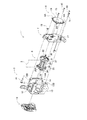
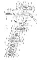
- FIG. 1 is an external perspective view of a seatbelt retractor according to the present embodiment. It is the perspective view which decomposed
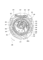
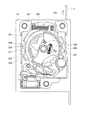
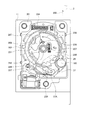
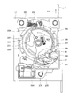
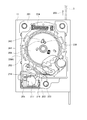
- FIG. 6 is a partially cutaway cross-sectional view showing a normal state of the lock unit. It is operation
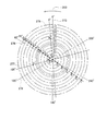
- movement explanatory drawing (lock state) by the vehicle body acceleration of a lock unit It is explanatory drawing of the coordinate system which shows the gravity center position of a lock arm. It is a figure which shows each coordinate position of the gravity center of a lock arm.
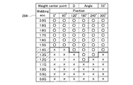
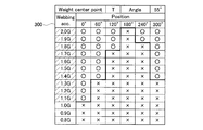
- 6 is an operation result table showing an example of an operation result for a webbing pull-out acceleration with respect to each revolution angle when the center of gravity of the lock arm is positioned at a coordinate position A.
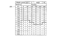
- 7 is an operation result table showing an example of an operation result for a webbing pull-out acceleration for each revolution angle when the center of gravity of the lock arm is positioned at a coordinate position B.
- 6 is an operation result table showing an example of an operation result for a webbing pull-out acceleration for each revolution angle when the center of gravity of the lock arm is positioned at a coordinate position C.
- 6 is an operation result table showing an example of an operation result for a webbing pull-out acceleration for each revolution angle when the center of gravity of the lock arm is positioned at a coordinate position D.
- 10 is an operation result table showing an example of an operation result for a webbing pull-out acceleration for each revolution angle when the center of gravity of the lock arm is positioned at a coordinate position E.
- 10 is an operation result table showing an example of an operation result for a webbing pull-out acceleration with respect to each revolution angle when the center of gravity of the lock arm is positioned at a coordinate position F.
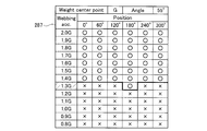
- 6 is an operation result table showing an example of an operation result for a webbing pull-out acceleration for each revolution angle when the center of gravity of the lock arm is positioned at a coordinate position G.
- 6 is an operation result table showing an example of an operation result for a webbing pull-out acceleration with respect to each revolution angle when the center of gravity of the lock arm is positioned at a coordinate position H.
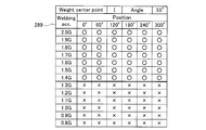
- 6 is an operation result table showing an example of an operation result for a webbing pull-out acceleration for each revolution angle when the center of gravity of the lock arm is positioned at a coordinate position I.
- 5 is an operation result table showing an example of an operation result for a webbing pull-out acceleration for each revolution angle when the center of gravity of the lock arm is positioned at a coordinate position J.
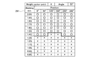
- 6 is an operation result table showing an example of an operation result for a webbing pull-out acceleration with respect to each revolution angle when the center of gravity of the lock arm is positioned at a coordinate position K.
- 7 is an operation result table showing an example of an operation result for a webbing pull-out acceleration for each revolution angle when the center of gravity of the lock arm is positioned at a coordinate position L.
- 6 is an operation result table showing an example of an operation result for a webbing pull-out acceleration for each revolution angle when the center of gravity of the lock arm is located at a coordinate position M.
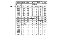
- 6 is an operation result table showing an example of an operation result for a webbing pull-out acceleration with respect to each revolution angle when the center of gravity of the lock arm is positioned at a coordinate position N.
- 10 is an operation result table showing an example of an operation result for a webbing pull-out acceleration for each revolution angle when the center of gravity of the lock arm is positioned at a coordinate position O.
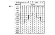
- 10 is an operation result table showing an example of an operation result for a webbing pull-out acceleration for each revolution angle when the center of gravity of the lock arm is positioned at a coordinate position P.
- 6 is an operation result table showing an example of an operation result for a webbing pull-out acceleration for each revolution angle when the center of gravity of the lock arm is positioned at a coordinate position Q.
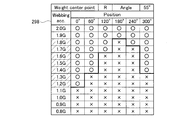
- 6 is an operation result table showing an example of an operation result for a webbing pull-out acceleration for each revolution angle when the center of gravity of the lock arm is positioned at a coordinate position R.
- 7 is an operation result table showing an example of an operation result for a webbing pull-out acceleration for each revolution angle when the center of gravity of the lock arm is positioned at a coordinate position S.
- 6 is an operation result table showing an example of an operation result for a webbing pull-out acceleration for each revolution angle when the center of gravity of the lock arm is positioned at a coordinate position T.
- 6 is an operation result table showing an example of an operation result for a webbing pull-out acceleration for each revolution angle when the center of gravity of the lock arm is positioned at a coordinate position U.
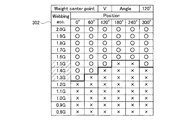
- 7 is an operation result table showing an example of an operation result for a webbing pull-out acceleration with respect to each revolution angle when the center of gravity of the lock arm is positioned at a coordinate position V.
- FIG. 7 is an operation result table showing an example of an operation result for a webbing pull-out acceleration for each revolution angle when the center of gravity of the lock arm is positioned at a coordinate position W.
- 6 is an operation result table showing an example of an operation result for a webbing pull-out acceleration for each revolution angle when the center of gravity of the lock arm is positioned at a coordinate position X.
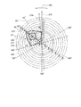
- FIG. 6 is a sensitivity error distribution diagram showing an example of a sensitivity error distribution with respect to a relationship between an angle in a webbing pull-out direction from a reference axis to a radius of a pivot shaft where the center of gravity of the lock arm is located, and a distance from a rotation center of the pivot shaft.
- FIG. 1 is an external perspective view of a seatbelt retractor 1 according to this embodiment.
- FIG. 2 is an exploded perspective view of the seat belt retractor 1 for each unit.
- the seat belt retractor 1 is a device for winding a webbing 3 of a vehicle, and includes a housing unit 5, a winding drum unit 6, a pretensioner unit 7, and a winding.
- a spring unit 8 and a lock unit 9 are included.
- the lock unit 9 is fixed to the side wall portion 12 of the housing 11 constituting the housing unit 5, and the webbing 3 is pulled out in response to a sudden pull-out of the webbing 3 or a rapid change in the acceleration of the vehicle as will be described later. Start operation to stop.
- the pretensioner unit 7 provided with a pretensioner mechanism 17 (see FIG. 3), which will be described later, is substantially omitted from the upper and lower end edges of the side plate portions 13 and 14 facing each other of the substantially U-shaped housing unit 5 in plan view.
- Each screw 15 inserted through from the outside of the pretensioner unit 7 is inserted into the screw fixing portions 13A, 13B, 14A formed with screw holes by extending in a right angle inner direction and the pin fixing portions 14B formed with through holes.
- the stopper pin 16 is screwed and inserted from the inside of the housing 11 and is fixed by a push nut 18 inserted into the stopper pin 16.
- the pretensioner unit 7 constitutes the other side wall portion facing the side wall portion 12 of the housing 11.
- take-up spring unit 8 is fixed to the outside of the pretensioner unit 7 by each ny latch 8A integrally formed with the spring case 19.
- the winding drum unit 6 around which the webbing 3 is wound and functions as a winding drum is rotatably supported between a lock unit 9 fixed to the side wall portion 12 of the housing unit 5 and the pretensioner unit 7.
- the winding drum unit 6 includes a guide drum 21, a drum shaft 22, a wire plate 25, a ratchet gear 26, and the like.
- the guide drum 21 is formed of an aluminum material or the like, and is formed in a substantially cylindrical shape in which the end surface portion on the pretensioner unit 7 side is closed. Further, a flange portion 27 extending in the radial direction from the outer peripheral portion and further extending in a substantially right-angled outward direction is formed on the end edge portion on the pretensioner unit 7 side in the axial direction of the guide drum 21. . In addition, a clutch gear 30 is formed on the inner peripheral surface of the flange portion 27 so that each clutch pawl 29 (see FIG. 4) is engaged and the rotation of the pinion gear body 33 (see FIG. 4) is transmitted in the event of a vehicle collision. ing.
- a cylindrical mounting boss 31 is erected at the center position of the end surface portion of the guide drum 21 on the pretensioner unit 7 side, and a drum shaft 22 formed of a steel material or the like is fixed by press fitting or the like. Further, the mounting boss 31 is fitted into a cylindrical portion 32A (see FIG. 4) of the bearing member 32 formed of a synthetic resin material such as polyacetal constituting a clutch mechanism 48 (see FIG. 4) described later.
- one end side of the winding drum unit 6 is rotatably supported by the bearing portion 33A (see FIG. 5) of the pinion gear body 33 constituting the pretensioner unit 7 via the bearing member 32.
- the tip of the drum shaft 22 of the take-up drum unit 6 is coupled to a spiral spring in the take-up spring unit 8 and constantly urges the take-up drum unit 6 in the winding direction of the webbing 3 by the urging force of the spiral spring. Structured.
- a flange portion 35 extending in the radial direction from the outer peripheral surface slightly inside from the end edge portion is formed. Further, the outer peripheral portion of the flange portion 35 is covered with a wire plate 25 having a substantially oval shape in a side view formed of an aluminum material or the like. A ratchet gear 26 is fixed to the outer central portion of the wire plate 25 by caulking or the like.
- the ratchet gear 26 has a disc shape formed of steel or the like, and has a ratchet gear portion 26A that engages with a pawl 37 (see FIG. 7) in the event of a vehicle collision or a vehicle emergency as described later.
- a shaft portion 28 is erected at the center position on the outer side of the ratchet gear 26.
- a spline is formed on the outer peripheral surface of the shaft portion 28, and the winding drum unit 6 is rotatably supported by the lock unit 9 via the shaft portion 28.
- FIG. 3 is a perspective view of the pretensioner unit 7 as viewed from the mounting surface side of the winding spring unit 8.
- 4 and 5 are exploded perspective views in which the pretensioner unit 7 is disassembled.
- FIG. 6 is a partially cutaway side view of the pretensioner unit 7.
- the pretensioner unit 7 includes a pretensioner mechanism 17, a forced lock mechanism 51 that rotates a pawl 37 (see FIG. 8) pivotally supported on the side wall portion 12 of the housing unit 5, and And the cover plate 53.
- the pretensioner mechanism 17 operates the gas generating member 41 at the time of a vehicle collision or the like, and uses the pressure of this gas via the flange portion 27 of the winding drum unit 6 to perform the winding. This is a mechanism for rotating the take-up drum unit 6 in the winding direction of the webbing 3.
- the pretensioner mechanism 17 is formed on the gas generation member 41, the pipe cylinder 42, the seal plate 43 and the piston 44 that move in the pipe cylinder 42 under the gas pressure of the gas generation member 41, and the piston 44.
- the pinion gear body 33 that rotates while meshing with the rack 44A formed, a base plate 45 to which the pipe cylinder 42 is attached, and a substantially rectangular parallelepiped arranged in contact with the side surface of the pipe cylinder 42 on the pinion gear body 33 side.
- a clutch mechanism 48 disposed on the outer surface of the base plate 45.
- the pinion gear body 33 has a substantially cylindrical shape formed of a steel material or the like, and a pinion gear portion 55 that meshes with a rack 44A formed on the piston 44 is formed on the outer periphery thereof. Further, a cylindrical support portion 56 extending outward from the end portion of the pinion gear portion 55 on the axial direction cover plate 53 side is formed. The support portion 56 is formed to have a length substantially equal to the thickness dimension of the cover plate 53 with the valley diameter of the pinion gear portion 55 as an outer diameter.
- a flange portion 57 projecting in the radial direction is formed at an end portion of the pinion gear portion 55 on the axial base plate 45 side.
- the boss 58 is formed with a bearing 33A into which the cylindrical shaft 32A of the bearing member 32 is inserted while the drum shaft 22 of the winding drum unit 6 is inserted in a substantially cylindrical shape outward from the flange 57. Is formed. Further, on the outer peripheral surface of the boss portion 58, three splines each having an outer diameter of the base end portion are formed at intervals of about 120 degrees of the central angle.
- the clutch mechanism 48 includes a bearing member 32 formed of a synthetic resin material such as polyacetal, a substantially annular pawl base 61 formed of a steel material, and three clutch pawls formed of a steel material. 29 and a substantially annular pawl guide 62 that is formed of a synthetic resin such as polyacetal and sandwiches each clutch pawl 29 together with the pawl base 61.
- the bearing member 32 has a substantially cylindrical shape in which a cylindrical mounting boss 31 erected at the center position of the end surface portion of the guide drum 21 on the pretensioner unit 7 side is rotatably fitted.
- the locking piece 32D is arranged at the distal end portion in the radial direction of each projecting portion 32C so as to face the outer peripheral surface of the cylindrical portion 32A in the axial direction, rather than the thickness dimension of the clutch mechanism 48. It is erected with a slightly lower height. Furthermore, an engaging protrusion is formed at the tip of each locking piece 32D and protrudes in a substantially right triangle shape in a side section in a substantially right angle outward direction.
- three spline grooves into which the splines formed on the boss portions 58 of the pinion gear body 33 are press-fitted are arranged at intervals of a central angle of about 120 degrees on the inner peripheral surface of the pawl base 61. It is formed one by one.
- the pawl base 61 has three insertion holes 65 into which the rotation support shafts 29A of the respective clutch pawls 29 are rotatably fitted, and the pawl base 61 is thick so as to surround each insertion hole 65 on the outer diameter side of the pawl base 61.
- Each pawl support block 66 is provided.
- a locking block 67 is formed at the outer diameter end of each pawl support block 66.
- each through hole 69 through which each locking piece 32 ⁇ / b> D of the bearing member 32 is inserted is formed at each vertex portion of the bottom surface of the recess 68.
- the inner peripheral diameter of the pawl guide 62 is formed larger than the spline groove of the pawl base 61, and the axially outer side surface portion of the pawl guide 62 has 3
- Each of the long and narrow positioning protrusions 71 protrudes along the radial direction at intervals of a central angle of 120 degrees.
- three locking hooks 72 that engage with the locking blocks 67 of the pawl base 62 are formed on the outer periphery of the pawl guide 62.
- each clutch pawl 29 is held in a state of being accommodated rotatably about the rotation support shaft 29.
- each positioning protrusion 71 protruding from the axially outer side surface portion of the pawl guide 62 of the clutch mechanism 48 is fitted into each positioning hole 75 of the base plate 45, so that the clutch mechanism 48 is attached to the base plate 45. Place on the outside.
- each spline formed in the boss portion 58 is replaced with each of the pawl base 61 constituting the clutch mechanism 48. Press fit into the spline groove.
- the clutch mechanism 48 and the pinion gear body 33 are disposed and fixed on the base plate 45, and the pinion gear portion 55 of the pinion gear body 33 is always positioned and fixed at the position shown in FIG.
- the cylindrical portion 32 ⁇ / b> A is fitted into the bearing portion 33 ⁇ / b> A of the pinion gear body 33 while the locking pieces 32 ⁇ / b> D of the bearing member 32 are inserted into the through holes 69 of the pawl base 61.
- the flange portion 32 ⁇ / b> B and each projecting portion 32 ⁇ / b> C of the bearing member 32 are fitted into the recessed portion 68.
- each protrusion 32C of the bearing member 32 are disposed so as to oppose the inner surface of each apex portion of the recess 68, and therefore the bearing member 32 cannot rotate relative to the pawl base 61. Attached to.
- the base block body 46 is made of a synthetic resin such as polyacetal.
- the gear housing 81 is formed in a substantially semicircular shape in a plan view from the side edge on the inner side of the base block body 46 and formed in a substantially ring shape with a bottom surface protruding outward.
- the flange portion 57 of the pinion gear body 33 is inserted into the through hole 82 in the bottom surface portion.
- each positioning boss 83 protruding from the side surface portion of the base block body 46 on the base plate 45 side is fitted into each positioning hole 85 of the base plate 45, and the base block body 46 is disposed on the inner surface of the base plate 45. .
- the base block body 46 faces the piston housing portion 42B in which the piston 44 is housed from the lower end portion facing the housing portion 42A in which the gas generating member 41 of the pipe cylinder 42 is housed to the position near the housing portion 42A.
- the block extension part 87 extended by a predetermined width for example, about 10 mm width
- a through-hole 89 through which a screw 88 (see FIG. 2) is inserted is formed at the lower end of the block extension 87.
- an elastic locking piece 46A extending from the outer side surface portion of the base block body 46 to the base plate 45 side and formed to be elastically deformable in the outer direction, and the upper side surface portion and the lower side surface of the base block body 46
- Each elastic locking piece 46 ⁇ / b> B extending from the portion toward the base plate 45 and elastically deformable in the outward direction is locked to the side end of the base plate 45.
- the base block body 46 is disposed on the base plate 45.
- the height of the gear housing portion 81 is formed to be approximately equal to the sum of the heights of the pinion gear portion 55 and the flange portion 57 of the pinion gear body 33.
- the forced locking mechanism 51 disposed in the base block body 46 will be described with reference to FIGS.
- the base block body 46 is formed with a recess 91 in which the forced lock mechanism 51 is disposed, and a push block 92 that constitutes the forced lock mechanism 51, a rotary lever 93, A block urging spring 92A for urging the push block 92 in the direction of the rotation lever 93, a gear side arm 94, and a urging spring 95 for urging the gear side arm 94 in the direction of the rotation lever 93 are provided.
- the gear side arm 94 is connected to a connecting shaft 96 constituting the forced lock mechanism 51 and a mechanical side arm 97 from the outside of the base plate 45.
- the rotary lever 93 is formed of a synthetic resin such as polyacetal, an aluminum material, or the like, and is formed in a substantially square shape, and a through hole is formed in a bent portion. Then, as shown in FIG. 6, the rotary lever 93 is rotatable on a boss 98 erected on the bottom surface of the concave portion 91 of the base block body 46 so that one end side thereof faces the pinion gear portion 55 of the pinion gear body 33. It is supported.
- the push block 92 is made of a synthetic resin such as polyacetal. As shown in FIG. 6, the push block 92 has one end positioned near the teeth of the pinion gear portion 55 of the pinion gear body 33 and the other end thereof by the positioning protrusion 101 erected on the bottom surface portion of the recess 91. It is positioned so as to be located in the vicinity of the rotation lever 93. Further, the push block 92 is urged toward the rotating lever 93 by a block urging spring 92A to prevent rattling.
- the rotation lever 93 can be rotated outward (counterclockwise in FIG. 6) by the push block 92 pushed by the teeth of the pinion gear portion 55. It is configured (see FIG. 9).
- the push block 92 is prevented from returning to the pinion gear body 33 side by the block biasing spring 92A.
- the gear side arm 94 is formed of a synthetic resin such as polyacetal, an aluminum material or the like and is formed in a substantially flat plate shape, and at one end side far from the rotation lever 93 on the side surface portion on the base block body 46 side, A boss 103 is erected to be inserted into the through hole 102 formed in the bottom surface portion of the recess 91 of the base block body 46. Further, a groove portion 105 having a predetermined depth through which the bent portion on one end side of the connecting shaft 96 is inserted is formed on a side surface portion where the boss 103 of the gear side arm 94 is erected.
- the gear side arm 94 has a stepped portion 106 formed on the upper surface of the distal end portion on the rotating lever 93 side so that the other end side of the rotating lever 93 abuts.
- the gear side arm 94 is rotatably supported on the rotating lever 93 side by inserting the boss 103 into the through hole 102 formed in the bottom surface of the recess 91. Further, the gear side arm 94 is urged by the urging spring 95 on the lower surface of the other tip end portion facing the step portion 106 (in the upward direction in FIG. 6), and the step portion 106. Is in contact with the other end of the rotary lever 93.
- the connecting shaft 96 is formed of a wire material such as a steel material, and is bent at a substantially right angle so that both ends face each other with a shift of about 90 degrees. Also. The length of the straight portion of the connecting shaft 96 is slightly longer than the width of the side plate portions 13 and 14 of the housing unit 5 (see FIG. 7).
- a groove 107 through which the bent portion on one end side of the connection shaft 96 is inserted extends from the outer peripheral portion in the through hole 102 formed in the bottom surface portion of the concave portion 91 of the base block body 46. ing. Further, a through hole 108 through which the one end side bent portion of the connection shaft 96 is inserted is formed in a portion of the base plate 45 facing the gear side arm 94.
- the one end side bent portion of the connecting shaft 96 passes through the through hole 108 of the base plate 45, the through hole 102 and the groove 107 of the base block body 46, and the gear side disposed in the recess 91 of the base block body 46.
- the arm 94 is inserted into the groove 105.
- the mechanical arm 97 is formed of a synthetic resin such as polyacetal, aluminum, or the like, and is formed into a substantially flat plate-like narrow fan shape, and on the outer surface of the edge on the central angle side.
- a boss 112 that is rotatably fitted in a through hole 111 (see FIG. 7) formed in the side wall portion 12 (see FIG. 7) of the housing unit 5 is provided upright.
- a boss 97 ⁇ / b> A that is inserted into the notch 113 (see FIGS. 7 and 8) is provided upright on the outer surface on the side wall 12 side of the outer peripheral edge of the mechanical arm 97.
- a groove 115 having a predetermined depth is formed on the inner side surface of the mechanical arm 97 along the center line.
- the mechanical side arm 97 is placed on the outer surface of the end edge portion on the central angle side of the mechanical side arm 97. It is attached to the other end side of the connecting shaft 96 so that the axial center of the boss 112 erected and the axial center of the connecting shaft 96 are substantially straight.
- the boss 112 of the mechanical arm 97 is rotatably inserted into the through hole 105 formed in the side wall portion 12 (see FIG. 8). Further, the boss 97 ⁇ / b> A of the mechanical arm 97 is inserted into a notch 138 formed in the side wall portion 12 and is rotatably attached to the inside of the side wall portion 12.
- the pipe cylinder 42 is formed in a substantially L shape with a steel pipe material or the like. And the one end side (lower bending part in FIG. 4) is comprised so that the substantially cylindrical accommodating part 42A may be formed and the gas generating member 41 may be accommodated.
- the gas generating member 41 includes explosives, and is configured to ignite the explosives according to an ignition signal from a control unit (not shown) and generate gas by combustion of the gas generating agent.
- the other end side of the pipe cylinder 42 (the upper bent portion in FIG. 4) is formed with a piston housing portion 42B having a substantially rectangular cross section, and a notch portion 117 is formed at a portion facing the pinion gear body 33, and the base plate 45, the pinion gear portion 55 of the pinion gear body 33 is configured to fit into the notch 117.
- the upper end portion of the piston accommodating portion 42B is provided with an opening 118 that is cut out so as to be inclined obliquely outward from a substantially central portion in the width direction of both side surfaces abutting against the base plate 45 and the cover plate 53. Yes.
- the pretensioner unit 7 is attached to the housing unit 5 on both sides of the piston housing portion 42B below the inclined portion 118A inclined toward the outside of the opening 118 formed at the upper end portion, and the piston 44 A pair of opposed through-holes 121 into which the stopper pin 16 functioning as a retaining member can be inserted is formed.
- the seal plate 43 is formed of a rubber material or the like into a substantially rectangular flat plate that can be inserted from the upper end side of the piston housing portion 42B, and has substantially the same shape as the gas pressure receiving side surface that receives the gas of the piston 44. Further, the seal plate 43 is a substantially cylindrical mounting convex portion that is fitted into a mounting concave portion 122 having a circular cross section having a predetermined depth (for example, a depth of about 4 mm) formed on the gas pressure receiving side surface of the piston 44. 123 is erected. A gas vent hole 124 communicating with the pressure receiving side surface for receiving the gas of the seal plate 43 is formed along the axial center at the center of the mounting convex portion 123.
- the piston 44 is formed of a steel material or the like, has a substantially rectangular cross section that can be inserted from the upper end side of the piston housing portion 42B, and has a long shape as a whole.
- a rack 44 ⁇ / b> A that meshes with the pinion gear portion 55 of the pinion gear body 33 is formed on the side surface of the piston 44 on the pinion gear body 33 side.
- a stepped portion 126 capable of contacting the stopper pin 16 is formed on the back surface of the front end portion (the upper end portion in FIG. 6) of the rack 44A.
- a pair of groove portions 127 having a predetermined depth are formed on both side surfaces of the rack 44A of the piston 44 from the upper edge of the step portion 126 to the cutting edge at the lower end of the rack 44A. They are formed so as to face each other along the longitudinal direction of the piston 44 up to the facing position.
- a through hole 128 having a rectangular cross section that is long along the longitudinal direction of the piston 44 is formed at the lower ends of the pair of grooves 127, and both side surface portions are communicated with each other.
- the mounting recess 122 and the through hole 128 formed on the pressure receiving side surface of the piston 44 are communicated with each other by a small communication hole 131 formed along the longitudinal direction of the piston 44.
- the seal plate 43 is set to the back side and press-fitted from the upper end side of the piston housing portion 42B to the back side. Further, the gas vent hole 124 of the seal plate 43 communicates with the through hole 128 via the communication hole 131 of the piston 44.
- the seal plate 43 is pressed by the pressure of the gas generated by the gas generating member 41, and the piston 44 moves to the upper end side opening 118 of the piston housing part 42B.
- the piston 44 is retracted to the back side of the piston housing part 42B, and the tip of the rack 44A is not engaged with the pinion gear part 55. It is located to become.
- the base plate is inserted into the notches 117 of the piston housing part 42B configured in this way while the protruding parts 109 projecting outward from both side edges of the gear housing part 81 of the base block body 46 are fitted.
- the pipe cylinder 42 is disposed on the 45.
- a rack retaining pin 133 having a substantially U-shaped cross-section standing on the gear housing portion 81 of the base block body 46 is inserted into the gear groove at the upper end of the rack 44A, and the vertical movement of the piston 44 is restricted. Is done. Further, the tip end portion of the piston 44 is located in the vicinity of the pinion gear portion 55 of the pinion gear body 33 and is in a non-meshing state.
- the piston accommodating portion 42B of the pipe cylinder 42 is separated from each of the ribs 134 having a substantially triangular cross-section standing on the side surface of the base block body 46 and the portion of the side edge of the base plate 45 facing the pinion gear body 33. Both side portions are supported by a back support portion 135 extending substantially at a right angle.
- the back support part 135 is extended so as to be substantially the same height as the piston housing part 42 ⁇ / b> B, and is located on the upper end side from the substantially central part of the edge part in the extending direction.
- a notch 136 having a predetermined width (for example, a width of about 8 mm) is formed with a predetermined depth (for example, about 4 mm).
- a lower end edge portion of the back support portion 135 is extended by a predetermined length (for example, about 4 mm) in a substantially perpendicular outer direction, and a lower corner portion of the back support portion 135 is provided with a cover plate 53.
- a stepped portion 137 having a height substantially equal to the thickness is formed.
- through holes 141 and 142 into which the tip of the back support part 135 can be inserted are formed at the side end part of the cover plate 53 facing the back support part 135 of the base plate 45.
- the side edge part which opposes the outer surface of the backrest part 135 of each through-hole 141,142 is predetermined height (for example, about 3 mm height) to an inner side direction (left direction in FIG. 4). It is depressed. Thereby, when each edge part of the extending direction of the back support part 135 is inserted in each through-hole 141,142, the inner surface of each through-hole 141,142 becomes an outer surface of the back support part 135. It is comprised so that it may contact
- the positioning bosses 143 that protrude from the side surface portion on the cover plate 53 side of the base block body 46 are covered with the cover.
- the cover plate 53 is disposed on the upper side of the base block body 46, the forced lock mechanism 51, the pipe cylinder 42, and the like by being fitted into the positioning holes 144 of the plate 53.
- the cylindrical support portion 56 of the pinion gear body 33 is fitted into the support hole 145 formed in the substantially central portion of the cover plate 53.
- the back support part 135 extending substantially at right angles from the side edge part of the base plate 45 is inserted into the through holes 141 and 142 formed in the side edge part facing the back support part 135 of the cover plate 53.
- An elastic locking piece 46C that extends from the outer side surface of the base block body 46 toward the cover plate 53 and is elastically deformable in the outer direction, and a cover from the upper side surface of the base block body 46.
- Elastic locking pieces 46 ⁇ / b> D that extend toward the plate 53 side and are formed so as to be elastically deformable in the outward direction are respectively locked to the side end portions of the cover plate 53.
- a screw 88 is inserted into a through hole 157 formed at a position facing the through hole 89 of the base block body 46 of the cover plate 53 and fastened to a screw hole 158 formed by burring processing of the base plate 45.
- the cover plate 53 is disposed and fixed to the base block body 46, and the pipe cylinder 42 is attached between the cover plate 53 and the base plate 45.
- the support portion 56 formed at the end of the pinion gear body 33 is rotatably supported by the support hole 145 of the cover plate 53.
- the base end portion of the boss portion 58 formed at both ends of the pinion gear body 33 and the support portion 56 are rotatably supported by the through hole 76 of the base plate 45 and the support hole 145 of the cover plate 53, respectively.
- each through hole 121 of the pipe cylinder 42, a through hole 147 formed at a position facing each through hole 121 of the cover plate 53, and a through hole formed at a position facing each through hole 121 of the base plate 45. 148 is arranged on the same axis.
- the stopper pin 16 formed of steel or the like is inserted into the through hole 148 of the base plate 45, the through holes 121 of the pipe cylinder 42, and the cover plate 53 from the pinning portion 14 ⁇ / b> B side of the housing 11. It can be inserted into the through hole 147 and fixed by the push nut 18.
- the pipe cylinder 42 is sandwiched between the cover plate 53 and the base plate 45, and both side surfaces are sandwiched between the base block body 46 and the backrest 135. Further, when the seal plate 43 is pressed by the pressure of the gas generated by the gas generating member 41 and the piston 44 moves to the upper end side opening (the upper end in FIG. 6) of the piston housing portion 42B, the piston 44 step portions 126 can be brought into contact with the stopper pins 16 inserted through the respective through holes 121 and stopped.
- the opening 118 on the upper end side of the piston accommodating portion 42B is a first extending portion that extends from the upper end edge of the cover plate 53 to the base plate 45 side at a substantially half width with respect to the piston accommodating portion 42B.
- the flat portion 118B perpendicular to the axial direction of the piston accommodating portion 42B of the opening 118 is covered by 151.
- the inclined portion 118A is covered by the second extending portion 152 that extends obliquely outward from the side end edge of the opening 118 of the first extending portion 151 on the inclined portion 118A side. Is called.
- an end edge portion of the first extension portion 151 on the base block body 46 side is extended by a predetermined length (for example, a length of about 4 mm) in the lower right direction.
- the base plate 45 is bent and extended with a predetermined width (for example, a width of about 3 mm) so as to face the outer end edge in the extending direction of the second extending portion 152 of the cover plate 53.
- the pressed portion 155 is provided.
- the pressing portion 155 has a predetermined width (for example, a width of about 3 mm) so as to be parallel to the second extending portion 152 from a position facing the through hole 148 at the upper end edge of the base plate 45. It extends a predetermined length (for example, about 8 mm) and is bent at a right angle so as to face the outer end edge in the extending direction of the second extending portion 152 from a substantially central portion.
- the opening 118 on the upper end side of the piston housing part 42B is covered with the first extending part 151 and the second extending part 152. Further, the outer end edge portion in the extending direction of the second extending portion 152 of the cover plate 53 faces the side surface portion of the pressing portion 155 of the base plate 45.
- FIG. 7 is an exploded perspective view of the housing unit 5.
- FIG. 8 is a side view of the seatbelt retractor 1 with the lock unit 9 removed.
- the housing unit 5 includes a housing 11, a bracket 161, a protector 163, a pawl 37, and a pawl rivet 165.
- the housing 11 is formed of a steel material or the like in a substantially U shape in plan view, and a through hole 166 into which the tip of the ratchet gear 26 of the winding drum unit 6 is inserted is formed in the side wall portion 12 on the back side. Has been. Further, a notch 113 is formed in a portion of the through hole 166 facing the obliquely lower pawl 37 so that the pawl 37 rotates smoothly. A through hole 168 for rotatably mounting the pawl 37 is formed on the lateral side of the notch 113.
- a semicircular guide portion 169 is formed on the concentric circle of the through hole 168 at a portion where the pawl 37 of the cutout portion 113 abuts.
- the portion of the pawl 37 that slides in contact with the guide portion 169 has a height substantially equal to the thickness dimension of the side wall portion 12 and a step that is recessed in an arc shape having the same curvature radius as the side edge of the guide portion 169.
- the part 37B is formed slightly higher than the thickness dimension of the side wall part 12.
- a guide pin 37 ⁇ / b> A that is inserted into a guide groove (not shown) of a clutch (not shown) that constitutes the lock unit 9 is erected at the tip of the outer side surface of the pawl 37. ing.
- the side plate portions 13 and 14 facing each other are extended from both side edge portions of the side wall portion 12.
- an opening is formed in the central portion of each of the side plate portions 13 and 14 to reduce the weight and improve the efficiency of attaching the webbing 3.
- upper and lower edge portions of the side plate portions 13 and 14 are formed with screwing portions 13A, 13B, and 14A and pinning portions 14B that extend in a substantially right-angle inner direction with a predetermined width.
- each screwing part 13A, 13B, 14A is formed with each screw hole 171 by which each screw 15 is screwed by burring, and the screwing part 14B has a through-hole 172 through which the stopper pin 16 is inserted. Is formed. Accordingly, as shown in FIGS. 2, 4, and 5, each screw 15 is inserted from each through hole 185 in the cover plate 53 to each through hole 186 in the base plate 45 and screwed into each screw hole 171. .
- bracket 161 attached to each upper end edge of the side plate portion 13 by a rivet 162 is formed of a steel material or the like, and webbing is performed on an extended portion that extends substantially inward from the upper end edge of the side plate portion 13.
- a horizontally long through-hole 173 from which 3 is pulled out is formed, and a horizontally long frame-shaped protector 163 formed of a synthetic resin such as nylon is fitted therein.
- a bolt insertion hole 178 into which a bolt 176 (see FIG. 8) is inserted when being attached to a fastening piece 175 (see FIG. 8) of the vehicle is formed at the lower end portion of the side plate portion 13.
- the pawl 37 formed of steel or the like is rotatably inserted into the through hole 168 from the outside of the side wall portion 12 with the stepped portion 37B being in contact with the guide portion 169.
- the pawl rivet 165 is rotatably fixed. Accordingly, the side surface of the pawl 37 and the side surface of the ratchet gear 26 are positioned so as to be substantially flush with the outer surface of the side wall portion 12.
- the pretensioner unit 7 when the pretensioner unit 7 is attached to the housing unit 5 by the screws 15, the stopper pins 16, and the push nuts 18, the pretensioner unit 7 is attached to the bent portion on the other end side of the connecting shaft 96.
- the boss 112 of the mechanical arm 97 is rotatably fitted in a through hole 111 formed in the side wall portion 12 and is positioned in the vicinity of the lower side surface portion of the pawl 37 located in the notch portion 113. .
- a boss 97 ⁇ / b> A standing on the outer side surface of the mechanical arm 97 is inserted into the notch 113.
- the pawl 37 is normally close to the mechanical arm 97 and is not engaged with the ratchet gear 26.
- a predetermined width from a position that is a predetermined height above the lower end surface of the side wall portion 12 (for example, a position that is about 10 mm above).
- the width is about 10 mm
- the arm protection fold is bent at a substantially right angle inward (toward the front in FIG. 7) so as to face the pawl 37 and the mechanical arm 97.
- a curved portion 180 is provided. That is, below the pawl 37 and the mechanical side arm 97 attached to the side wall portion 12, a predetermined length (for example, a length of about 10 mm) is set at a substantially right angle so as to face the mechanical side arm 97 with a predetermined width.
- An arm protection bent portion 180 extending inward is provided.
- a laterally long opening 181 is formed in a portion of the side wall portion 13 that faces the connecting shaft 96, and faces the entire length of the connecting shaft 96, and is substantially inward from the lower edge of the opening 181.
- a shaft protecting bent portion 182 that is bent at a right angle is provided. Further, the end edge portion on the guide drum 21 side of the shaft protecting bent portion 182 extends so as to be inside the connecting shaft 96 facing the side wall portion 13.
- a bolt insertion hole 178 is formed below the shaft protecting bent portion 182, and a bolt 176 is inserted into the bolt insertion hole 178 and fixed to a vehicle fastening piece 175 by a nut 177.
- FIG. 9 is an explanatory view showing a state where the piston 44 is moved by the operation of the gas generating member 41 of the pretensioner mechanism 17 and the lower end portion of the rotation lever 93 is disengaged from the tip end portion of the gear side arm 94.
- FIG. 10 is an explanatory view showing the operation of the pawl 37 corresponding to FIG.
- the gear side arm 94 is pressed outward by the biasing spring 95 and rotates in the counterclockwise direction when viewed from the front (in the direction of the arrow X3).
- the push block 92 is pressed outward by the block biasing spring 92A and is maintained in a state of being separated from the pinion gear portion 55 of the pinion gear body 33, and the upper end portion of the rotary lever 93 is abutted against the inner wall surface of the recess 91. Keep in contact.
- the mechanical side arm 97 has the other end side bent portion of the connecting shaft 96 inserted into the groove 115, and therefore, when the gear side arm 94 rotates, it is counterclockwise when viewed from the front (in the direction of arrow X8).
- the pawl 37 is engaged with the ratchet gear portion 26A of the ratchet gear 26.
- the pawl 37 and the ratchet gear portion 26A of the ratchet gear 26 are configured to mesh with each other so as to prevent the winding drum unit 6 from rotating in the webbing 3 pull-out direction and to allow rotation in the webbing 3 winding direction. ing.
- the gas generated from the gas generating member 41 presses the pressure receiving side surface of the seal plate 43, and the mounting recess 122 and the through hole 128 formed on the pressure receiving side surface of the piston 44 from the gas vent hole 124 of the seal plate 43.
- the liquid flows out in the directions of the arrows X4 to X7 through the communicating holes 131.
- the first extending portion 151 and the second extending portion 152 of the cover plate 53 that cover the opening 118 of the piston accommodating portion 42B are pressed outward by the gas pressure, but the second extending portion 152 Since the outer edge in the extending direction is pressed against the pressing portion 155 of the base plate 45, the gas is discharged from the gap between the opening 118 and the first extending portion 151 and the second extending portion 152.
- FIG. 11 is an exploded perspective view of the lock unit 9 as seen from the mechanism cover side.
- FIG. 12 is an exploded perspective view of the lock unit as seen from the mechanism block side.
- FIG. 13 is an assembly sectional view including the lock arm of the lock unit.
- FIG. 14 is a partially cutaway cross-sectional view showing a normal state of the lock unit.
- the lock unit 9 is a unit that performs operations of the webbing sensitive lock mechanism and the vehicle body sensitive lock mechanism.
- the lock unit 9 includes a mechanism block 201, a clutch 202, a pilot arm 203, a return spring 204, a vehicle sensor 205, a locking gear 206, a sensor spring 207, a lock arm 208, an inertia mass 209, and a mechanism cover 210.
- the mechanism block 201 has a substantially bowl-shaped opening 212 that is inverted at the center.
- the large diameter portion of the opening 212 is formed to be larger than the outer diameter of the ratchet gear portion 26 ⁇ / b> A of the ratchet gear 26 and smaller than the outer diameter of the clutch 202.
- the ratchet gear 26 is disposed in close proximity to the back surface of the clutch 202 at the large diameter portion of the opening 212, and the shaft portion 28 (see FIG. 8) of the ratchet gear 26 is formed at the center of the clutch 202.
- the inserted through hole 213 is inserted.
- a pawl 37 that is pivotally supported on the housing 11 by a pawl rivet 165 is disposed in the small diameter portion of the opening 212, and a connecting portion between the large diameter portion and the small diameter portion of the opening 212 is the pawl 37.
- a through hole 214 into which the head of the pawl rivet 165 is loosely fitted when the lock unit 9 is attached to the housing 11 is provided on the side of the connecting portion between the large diameter portion and the small diameter portion of the opening 212. Is formed.
- a concave portion having a substantially rectangular cross section is formed in the other lower end side corner portion (the lower left corner portion in FIG. 11) facing the lower end side corner portion where the small diameter portion of the opening 212 is located.
- the sensor mounting portion 215 formed on the vehicle is provided, and the vehicle sensor 205 is provided.
- the vehicle sensor 205 includes a case 216 formed in a container shape having a rectangular cross section, and a metal sphere 217 disposed so as to be able to roll on a substantially dish-shaped mounting portion formed on the bottom surface of the case 216. From the vehicle sensor lever 218, which is placed on the upper side of the sphere 217 and is supported so that the end edge (the left edge in FIG. 14) opposite to the pawl 37 can swing in the vertical direction. It is configured.
- the vehicle sensor 205 includes a pair of locking holes 220 (see FIG. 5) in which the engaging claws 219 projecting from both end edges of the case 216 are formed at both end edges of the sensor placement portion 215. 12, one locking hole 220 is shown and is locked by being inserted into the sensor mounting portion 215.
- each rib 222 is formed concentrically so as to protrude radially outward.
- four contact pieces 223 extending from the upper end portion facing each rib 222 with a predetermined width in a substantially right angle inner direction are provided. Then, by fitting each rib 222 of the clutch 202 to the lower side of each contact piece 223 of the mechanism block 201, the clutch 202 is attached to the mechanism block 201 so as to be rotatable.
- the side wall portion of the mechanism block 201 is notched at a predetermined width at the upper end portion of the mechanism block 201, and extends from the both end portions of the notch portion substantially upward at a right angle.
- inserted by the side wall of the webbing winding direction side (it is the left side in FIG.11, FIG.13, FIG.14) of the said notch part of the mechanism block 201 is provided. It protrudes inward.
- the upper end portion of the clutch 202 has a U-shaped cross section so as to face the side wall of the notch portion of the mechanism block 201 on the webbing pull-out direction side (right side in FIGS. 11, 13, and 14).
- the spring receiving rib 226 protrudes outward.
- the spring receiving rib 226 is provided with a protruding holding portion 227 that is fitted to the other end of the return spring 204 in an inward direction. Accordingly, as shown in FIGS. 13 and 14, the clutch 202 is rotated with respect to the mechanism block 201 in the webbing take-up direction side by fitting both ends of the return spring 204 into the protruding holding portions 225 and 227. As shown in FIG.
- An annular rib portion 228 is erected on the mechanism cover 210 side of the clutch 202 so as to be coaxial with the through-hole 213, and an inner surface of the rib portion 228 has a lock arm 208 as described later.
- a clutch gear 229 with which the engaging claw 231 is engaged is formed (see FIG. 16). As will be described later, the clutch gear 229 is formed so as to engage with the engaging claw 231 of the lock arm 208 only when the locking gear 206 rotates in the webbing pull-out direction with respect to the axis of the through hole 231. (See FIG. 16).
- a mounting boss 233 that is fitted into a through-hole 232 formed in the central portion of the pilot arm 203 is erected at a substantially central portion in the left-right direction.
- the arm 203 is pivotally supported so as to be rotatable. As shown in FIG. 14, the pilot arm 203 is normally in contact with the vehicle sensor lever 218, and is pushed up to the locking gear 206 side by the movement of the sphere 217 by the vehicle sensor lever 218, and is engaged with the locking gear teeth 206A. It is configured to be compatible.
- a guide groove 235 into which the guide pin 37A of the pawl 37 is loosely fitted is formed on the surface on the mechanism block 201 side opposite to the mounting boss 233 of the clutch 202.
- the guide groove 235 is formed so as to approach the axial center of the through-hole 213 toward the upper side in the webbing winding direction (the upper left direction in FIG. 14).
- the locking gear 206 is erected in an annular shape from the entire circumference of the disk-shaped bottom surface portion 236 having a diameter larger than the outer diameter of the annular rib portion 228 of the clutch 202 toward the clutch 202 side, Locking gear teeth 206A that engage with the pilot arm 203 are formed.
- the locking gear teeth 206A are formed to engage with the pilot arm 203 only when the locking gear 206 rotates in the webbing pull-out direction (see FIG. 20).
- a cylindrical fixed boss 237 is erected at the center of the bottom surface portion 236 of the locking gear 206 so as to penetrate from the front side to the back side.
- the inner surface of the fixed boss 237 has a ratchet.
- a spline groove into which a spline 28A (see FIG. 8) formed on the outer peripheral surface of the shaft portion 28 of the gear 26 is fitted is formed. Then, the shaft portion 28 loosely fitted into the through hole 231 of the clutch 202 is fitted into the fixed boss 237 of the locking gear 206, so that the ratchet gear 26 and the locking gear 206 of the winding drum unit 6 cannot be relatively rotated coaxially. It is press-fitted and fixed.
- a cylindrical support boss 238 is erected on the surface on the clutch 202 side of the bottom surface portion 236 of the locking gear 206 at a height lower than the locking gear teeth 206A adjacent to the fixed boss 237.
- the synthetic resin lock arm 208 formed in a substantially arcuate shape so as to surround the fixed boss 237 is supported by a pivot shaft 239 erected on the edge of the fixed boss 237 side in the substantially central portion in the longitudinal direction.
- the boss 238 is rotatably inserted and pivotally supported.
- the lock arm 208 is formed with a groove portion 240 that is substantially similar to the outer shape and opens to the bottom surface portion 236 side of the locking gear 206 along the longitudinal direction. Then, a substantially flat inertia mass 209 made of a metal such as iron or stainless steel formed in a substantially arcuate shape is fitted and attached in the groove portion 240. As a result, the lock arm 208 to which the inertia mass 209 is attached functions as an inertial body that generates an inertial delay with respect to the sudden withdrawal of the webbing 3.
- the lock arm 208 is provided with an elastic locking piece 241 having an inverted L-shaped cross section on the lateral side of the pivot shaft 239 so as to stand on the bottom surface 236 side of the locking gear 206.
- This elastic locking piece 241 is inserted into a window portion 242 (see FIGS. 11 and 19) having a substantially step shape and formed in the base end portion of the support boss 238 of the locking gear 206, and the shaft of the support boss 238 is It is elastically locked so that it can rotate around the center.
- the locking gear 206 includes a spring support pin 243 into which one end side of the sensor spring 207 is fitted into a rib portion extending radially outward from the outer peripheral surface of the fixed boss 237. It is erected in the webbing pull-out direction orthogonal to the axis of the fixed boss 237. Further, on the side wall of the lock arm 208 facing the spring support pin 243, a spring support pin 244 into which the other end side of the sensor spring 207 is fitted is provided upright.
- the spring support pin 243 functions as an example of a gear side spring support pin.
- the spring support pin 244 functions as an example of an inertial body side spring support pin.
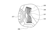
- the spring support pin 243 erected in parallel with the bottom surface portion 236 of the locking gear 206 is formed in an elongated substantially truncated cone shape. Further, the spring support pin 244 erected on the side wall of the lock arm 208 facing the spring support pin 243 is a concave portion that is recessed in a predetermined depth (for example, a depth of about 2 mm to 3 mm) in a U shape in plan view. A gap for loosely inserting the sensor spring 207 is formed on both sides of the lock arm 208 in the longitudinal direction.
- the spring support pin 244 of the lock arm 208 is formed in a tapered shape in which the outer peripheral surface of the distal end portion is cut obliquely from the pivot shaft 239 side toward the distal end portion on the opposite side to the pivot shaft 239. ing.
- the spring support pin 244 of the lock arm 208 is engaged when the lock arm 208 is rotated in the webbing take-up direction against the urging force of the sensor spring 207 and engaged with the clutch gear 229 as described later.
- the outer peripheral surface of the sensor spring 207 approaching the bent inner side is sharpened so that the outer peripheral surface on the tip side is substantially along the inner side of the sensor spring 207 that is bent and deformed into a substantially elongated S shape. (See FIG. 16).
- the spring support pin 244 of the lock arm 208 is locked at the tip when the lock arm 208 is rotated in the webbing take-up direction against the biasing force of the sensor spring 207 and engaged with the clutch gear 229. It is erected at a height that is located near the tip of the spring support pin 243 of the gear 206 (see FIG. 16).
- the outer edge of the engaging claw 231 is
- the locking gear 206 is configured to be able to come into contact with a spindle-shaped detent 247 erected on the bottom surface 236 of the locking gear 206 (see FIG. 16).
- the tip of the spring support pin 244 of the lock arm 208 is located at the substantially center of the inner side of the sensor spring 207 that is bent and deformed into a substantially slender S shape, and the outer peripheral surface of the tip portion on the side of the pivot shaft 239 is substantially slender. It is almost along the inside of the sensor spring 207 which is bent and deformed in an S shape.
- the lock unit 9 is covered with a mechanism cover 210 formed of a synthetic resin.
- the mechanism cover 210 is a substantially box-shaped cover case that is open on the housing 11 side, and is provided with nai latches 249 having the same configuration as that of the nai latch 8A at three positions, the upper corner portions and the lower end edge central position. Yes.
- a cylindrical support boss 251 into which a fixed boss 237 protruding from the bottom surface portion 236 of the locking gear 206 is slidably fitted is erected at the center of the mechanism cover 210 on the housing 11 side.
- the lock unit 9 first attaches the lock arm 208 and the sensor spring 207 to which the inertia mass 209 is attached to the locking gear 206.
- a return spring 204, a clutch 202, a pilot arm 203, a vehicle sensor 205, and a locking gear 206 are disposed. Thereafter, the fixed boss 237 of the locking gear 206 is fitted into the support boss 251 of the mechanism cover 210, and each ny latch 249 is inserted into each through hole 252 of the mechanism block 201.
- the lock unit 9 inserts the shaft portion 28 loosely fitted into the opening 212 of the mechanism block 201 into the fixed boss 237 of the locking gear 206 through the through hole 231 of the clutch 202, and The 249 is pushed into each through hole 253 (see FIG. 8) provided at three locations on the side wall portion 12 of the housing 11, thereby being fixed to the outside of the side wall portion 12.
- the shaft portion 28 of the winding drum unit 6 is rotatably supported by the support boss 251 of the mechanism cover 210 attached to the outside of the side wall portion 12 of the housing 11 via the fixed boss 237 of the lock gear of the lock unit 9. Is done.
- members other than the inertia mass 209, the return spring 204, the sensor spring 207, and the sphere 217 of the vehicle sensor 205 are formed of a resin member. It is a small thing.
- the pulling-out direction of the webbing 3 is the arrow 255 direction.
- the counterclockwise rotation direction is the rotation direction (webbing pull-out direction) of the winding drum unit 6 when the webbing 3 is pulled out.
- the operation related to the locking operation will be mainly described, and description of other portions will be omitted as appropriate.
- a part of the drawing is cut out and displayed as necessary.
- the operation of the pawl 37 is common to both the “webbing sensitive lock mechanism” and the “vehicle body sensitive lock mechanism”. For this reason, in FIG. 15 thru
- FIGS. 15 to 18 are explanatory diagrams for explaining the operation of the “webbing sensitive lock mechanism”.
- the portion indicating the relationship between the pawl 37 and the ratchet gear 26 in addition to the portion indicating the relationship between the lock arm 208 and the clutch gear 229 and the portion indicating the movement of the sensor spring 207 are cut off. Missing shows.
- the lock arm 208 to which the inertia mass 209 is attached has the pivot shaft 239 rotatably supported by the support boss 238 of the locking gear 206.
- a predetermined acceleration for example, about 1.5 G. 1G ⁇ 9.8 m / s 2
- the locking gear 206 rotates in the webbing pull-out direction (in the direction of arrow 256).
- a delay in inertia occurs in the lock arm 208.
- the lock arm 208 that has been in contact with the stopper 245 rotates in the clockwise direction around the pivot shaft 239 with respect to the locking gear 206 in order to maintain the initial position against the urging force of the sensor spring 207. It is rotated until it comes into contact with the detent 247. Therefore, the engagement claw 231 of the lock arm 208 is rotated radially outward with respect to the rotation shaft of the locking gear 206 and engaged with the clutch gear 229 of the clutch 202.
- the winding drum unit 6 is moved in the webbing winding direction (the direction opposite to the arrow 256) by the urging force of the winding spring unit 8.
- the clutch 202 is rotated in the webbing winding direction (clockwise in FIG. 18) by the urging force of the compressed return spring 204.
- lock arm 208 is rotated in the webbing pull-out direction (in the counterclockwise direction in FIG. 18) by the urging force of the sensor spring 207 and is brought into contact with the stopper 245 so that the engagement claw of the lock arm 208 is engaged. 231 and the clutch gear 229 are disengaged (see FIG. 15).
- FIGS. 19 to 22 are explanatory diagrams for explaining the operation of the “vehicle body sensitive locking mechanism”.
- the portion of the case 216 of the vehicle sensor 205 is cut away.
- the sphere 217 of the vehicle sensor 205 is placed on the dish-shaped bottom surface of the case 216. Therefore, the acceleration due to the shaking or tilting of the vehicle body is a predetermined acceleration (for example, about 1 If it exceeds 5 G), the bottom surface of the case 216 is rolled to push up the vehicle sensor lever 218.
- a predetermined acceleration for example, about 1 If it exceeds 5 G
- the pilot arm 203 whose one end is in contact with the vehicle sensor lever 218 is rotatably attached to the attachment boss 233 of the clutch 202, so that it is pushed up by the vehicle sensor lever 218 and attached. It is rotated clockwise (in the direction of arrow 258) around the axis of the boss 233.
- the tip of the pilot arm 203 on the vehicle sensor 205 side is engaged with a locking gear tooth 206 ⁇ / b> A formed on the outer periphery of the locking gear 206.
- the clutch 202 rotates in the webbing pull-out direction around the axis of the fixed boss 237 of the locking gear 206 against the urging force of the return spring 204. Moved.
- the guide pin 37A of the pawl 37 is guided to the guide groove 235 of the clutch 202, so the pawl 37 is rotated to the ratchet gear 26 side. (In the direction of arrow 261).
- the winding drum unit 6 is moved in the webbing winding direction (the direction opposite to the arrow 256) by the urging force of the winding spring unit 8. To be rotated. As a result, the engagement between the pilot arm 203 and the locking gear teeth 206A is released, and the clutch 202 is moved in the webbing winding direction (clockwise in FIG. 22) by the urging force of the compressed return spring 204. It is rotated.
- the guide pin of the pawl 37 is rotated as the clutch 202 rotates in the webbing take-up direction.
- 37A is guided in the reverse direction through the guide groove 235 of the clutch 202, is separated from the ratchet gear 26, and the locked state of the winding drum unit 6 by the pawl 37 is released (see FIG. 19).
- the pilot arm 203 is rotated toward the vehicle sensor 205 by its own weight and is brought into contact with the vehicle sensor lever 218.
- FIG. 23 shows an example in which the variation (sensitivity error characteristic) of the pull-out acceleration of the webbing 3 necessary for rotating and engaging the lock arm 208 with the clutch gear 229 is examined. It demonstrates based on thru
- the variation (sensitivity error characteristic) in the pull-out acceleration of the webbing 3 necessary for revolving the lock arm 208 around the rotation axis of the locking gear 206 by a predetermined angle and engaging the lock arm 208 with the clutch gear 229 is obtained.
- the variation (sensitivity error characteristic) was examined.
- a measurement method for measuring the pull-out acceleration of the webbing 3 necessary for rotating the locking gear 206 by a predetermined angle in the webbing pull-out direction and engaging the lock arm 208 with the clutch gear 229 will be described with reference to FIG. .
- the lock arm 208 is rotated in the webbing pull-out direction (in the direction of the arrow 262) by the urging force of the sensor spring 207, and the engaging claw 231 side edge is normally a stopper. 245 abuts.
- a straight line connecting the rotation shaft 271 of the locking gear 206 and the rotation shaft 272 of the pivot shaft 239 is defined as a reference straight line 273.
- a straight line 275 is set by rotating the reference straight line 273 around the rotation axis 272 of the pivot shaft 239 by the angle ⁇ in the webbing pull-out direction. Subsequently, in a state where the edge of the lock arm 208 on the engagement claw 231 side is in contact with the stopper 245, the center of gravity position GP of the lock arm 208 is set on the straight line 275 to the radius from the rotation shaft 272.
- the position is set to RD (for example, the radius RD is 0.0 mm to 2.0 mm).
- the locking gear 206 is rotated by a predetermined angle in the webbing pull-out direction (for example, the central angle is 5 degrees), that is, the reference straight line 273 is rotated around the rotation axis 271 with the state shown in FIG.
- a predetermined angle in the webbing pull-out direction for example, the central angle is 5 degrees
- the reference straight line 273 is rotated around the rotation axis 271 with the state shown in FIG.
- the locking gear 206 is rotated by a central angle of 60 degrees in the webbing pull-out direction (in the direction of arrow 262 in FIG. 23), and the pull-out acceleration of the webbing 3 is obtained at each rotation position.
- the pull-out acceleration of the webbing 3 was obtained at each rotation position.
- the lock arm 208 When the pulling acceleration of the webbing 3 is “1.4 G”, the lock arm 208 is engaged with the clutch gear 229 when the locking gear 206 is in the reference state and in the state rotated by 60 ° in the webbing pulling direction. I didn't. Further, when the pulling acceleration of the webbing 3 is “1.3 G”, the lock arm 208 is the clutch when the locking gear 206 is in the reference state, in the state rotated by 60 ° in the webbing pull-out direction, and in the state rotated by 300 °. The gear 229 was not engaged.
- the locking gear 206 When the pulling acceleration of the webbing 3 is “1.2 G”, the locking gear 206 is in a reference state, a state rotated by 60 ° in the webbing pulling direction, a state rotated by 120 °, and a state rotated by 300 °. At times, the lock arm 208 did not engage the clutch gear 229. Further, when the pulling acceleration of the webbing 3 was “1.1 G” or less, the lock arm 208 was not engaged with the clutch gear 229 at all the rotational positions of the locking gear 206.
- the webbing 3 is set when the gravity center position GP is set to a coordinate position O having a radius of 0.2 mm opposite to the lock arm 208 from the rotation shaft 272 of the pivot shaft 239 on the straight line 276.
- the operation result of the locking gear 206 with respect to the pull-out acceleration will be described with reference to FIG.
- the webbing 3 is set when the gravity center position GP is set to the coordinate position P having a radius of 0.4 mm opposite to the lock arm 208 from the rotation shaft 272 of the pivot shaft 239 on the straight line 276.
- the operation result of the locking gear 206 with respect to the pull-out acceleration will be described with reference to FIG.
- the webbing 3 is set when the gravity center position GP is set to a coordinate position Q having a radius of 0.6 mm opposite to the lock arm 208 from the rotation shaft 272 of the pivot shaft 239 on the straight line 276.
- the operation result of the locking gear 206 with respect to the pull-out acceleration will be described with reference to FIG.
- the webbing 3 is set when the center of gravity position GP is set to the coordinate position R having a radius of 0.8 mm opposite to the lock arm 208 from the rotation shaft 272 of the pivot shaft 239 on the straight line 276.
- the operation result of the locking gear 206 with respect to the pull-out acceleration will be described with reference to FIG.
- the webbing 3 is set when the gravity center position GP is set to the coordinate position S having a radius of 1.0 mm opposite to the lock arm 208 from the rotation shaft 272 of the pivot shaft 239 on the straight line 276.
- the operation result of the locking gear 206 with respect to the pull-out acceleration will be described with reference to FIG.
- the webbing 3 is set when the gravity center position GP is set to a coordinate position T having a radius of 1.2 mm opposite to the lock arm 208 from the rotation shaft 272 of the pivot shaft 239 on the straight line 276.
- the operation result of the locking gear 206 with respect to the pull-out acceleration will be described with reference to FIG.
- the gravity center position GP is set to a coordinate position U having a radius of 0.7 mm on the lock arm 208 side from the rotation shaft 272 of the pivot shaft 239 on the straight line 277. Then, with the state shown in FIG. 23 as a reference state, the locking gear 206 is rotated by a center angle of 60 degrees in the webbing pull-out direction (indicated by the arrow 262 in FIG. 23), and the pull-out acceleration of the webbing 3 is obtained at each rotation position.
- the state shown in FIG. 23 as a reference state
- the locking gear 206 is rotated by a center angle of 60 degrees in the webbing pull-out direction (indicated by the arrow 262 in FIG. 23), and the pull-out acceleration of the webbing 3 is obtained at each rotation position.
- the lock arm 208 was engaged with the clutch gear 229 at each pulling acceleration was measured.
- the center of gravity position GP is set to a coordinate position V having a radius of 0.1 mm on the lock arm 208 side from the rotation shaft 272 of the pivot shaft 239 on the straight line 278. Then, with the state shown in FIG. 23 as a reference state, the locking gear 206 is rotated by a center angle of 60 degrees in the webbing pull-out direction (indicated by the arrow 262 in FIG. 23), and the pull-out acceleration of the webbing 3 is obtained at each rotation position.
- the state shown in FIG. 23 as a reference state
- the locking gear 206 is rotated by a center angle of 60 degrees in the webbing pull-out direction (indicated by the arrow 262 in FIG. 23), and the pull-out acceleration of the webbing 3 is obtained at each rotation position.
- the lock arm 208 was engaged with the clutch gear 229 at each pulling acceleration was measured.
- the operation result table 302 indicating the operation result of the locking gear 206 with respect to the pulling acceleration of the webbing 3 when the pulling acceleration of the webbing 3 is “1.6 G” or more, all of the locking gears 206 are displayed. In the rotational position, the lock arm 208 was engaged with the clutch gear 229. Further, when the pulling acceleration of the webbing 3 is “1.5 G” to “1.3 G”, the lock arm 208 is engaged with the clutch gear 229 at each rotational position of the locking gear 206, and the lock arm 208 is engaged. Is not engaged with the clutch gear 229. Further, when the pulling acceleration of the webbing 3 is “1.2 G” or less, the lock arm 208 is not engaged with the clutch gear 229 at all the rotational positions of the locking gear 206.
- the sensitivity error distribution chart 311 shows that the angle ⁇ in the webbing pull-out direction from the reference straight line 273 to each straight line where the center of gravity position GP of the lock arm 208 is set on the horizontal axis is from 0 ° to 360 °. It is set.
- the radius RD from the rotation axis 272 of the pivot shaft 239, that is, the rotation center of the lock arm 208 to the center of gravity GP of the lock arm 208 is 0.0 mm to 2.0 mm. It is set.
- the variation in the pull-out acceleration of the webbing 3 in which the lock arm 208 engages with the clutch gear 229 is formed in a generally rice ball-shaped section 313 that protrudes upward on the lower left side. ) Is “0.2 G or less”.
- the outer section 314 of the section 313 has a variation in the pull-out acceleration (sensitivity error) of the webbing 3 where the lock arm 208 engages the clutch gear 229 is “0.3 G or less”. It is a parcel.
- the distribution area of the gravity center position GP of the lock arm 208 corresponding to each of the sections 312 and 313 in the sensitivity error distribution diagram 311 will be described with reference to FIG. 50 is the same as the configuration of FIG. 24 with the state shown in FIG. 23 as a reference state, and the coordinate positions A to X indicate the same coordinate position on the lock arm 208. That is, as shown in FIG. 23, the lock arm 208 is rotated in the webbing pull-out direction (in the direction of the arrow 262) by the urging force of the sensor spring 207, and the end edge portion on the engagement claw 231 side becomes the stopper 245. It is in a contact state.
- the distribution region 316 of the center of gravity position GP of the lock arm 208 corresponding to the section 312 of the sensitivity error distribution diagram 311 has the reference straight line 273 around the rotation axis 272 of the pivot shaft 239 in the webbing withdrawal direction (FIG. 50).
- the distribution region 316 of the center of gravity position GP of the lock arm 208 is gradually narrowed away from the bisector 276 in both circumferential directions, and both end portions are almost at the boundary portions formed by the straight lines 321 and 322. It is a substantially rhombic region in contact. Therefore, by setting the center of gravity position GP of the lock arm 208 to be located within the distribution region 316, the variation (sensitivity error) in the pull-out acceleration of the webbing 3 with which the lock arm 208 engages with the clutch gear 229 is expressed as “ It can be set to “0.1 G or less”.
- ⁇ 108 °.
- the lock arm 208 has a maximum width from a radius of 0.12 mm to a radius of 0.9 mm.
- the distribution region 317 of the center of gravity position GP of the lock arm 208 is gradually narrowed away from the bisector 276 in both circumferential directions, and both end portions are at the boundary portion formed by the reference straight line 273 and the straight line 323. It is a substantially rhombic region that is almost in contact. Therefore, by setting the center of gravity position GP of the lock arm 208 so as to be located in the distribution region 317, the variation (sensitivity error) in the pull-out acceleration of the webbing 3 with which the lock arm 208 engages the clutch gear 229 is expressed as “ It can be set to “0.2 G or less”. Note that the distribution regions 316 and 317 are substantially similar.
- the lock arm 208 is configured so that the center of gravity GP of the lock arm 208 is set within the distribution region 317 (see FIG. 50).
- the variation (sensitivity error) of the drawing acceleration of the webbing 3 engaged with the clutch gear 229 can be set to “0.2 G or less”.
- the winding drum unit 6 is locked in an emergency. It is possible to stabilize the operation sensitivity of the emergency lock mechanism in which the pawl 37 engages with the ratchet gear portion 26A of the ratchet gear 26 by setting the variation in the pull-out acceleration of the webbing 3 to 0.2 G or less.
- the winding drum unit 6 is locked in an emergency. It is possible to further stabilize the operation sensitivity of the emergency lock mechanism in which the pawl 37 is engaged with the ratchet gear portion 26A of the ratchet gear 26 by setting the variation in the pull-out acceleration of the webbing 3 to 0.1 G or less.
- the lock arm 208 is made of only a synthetic resin. Can be made smaller. Further, by changing the shape of the metal inertia mass 209, the gravity center position GP of the lock arm 208 engaged with the clutch gear 229 can be easily set. Furthermore, since the engaging claw 231 that engages with the clutch gear 229 is formed at one end of the lock arm 208 made of synthetic resin, the structure of the lock arm 208 can be simplified.
- the spring support pin 244 of the lock arm 208 is formed in a tapered shape in which the outer peripheral surface of the distal end portion is cut obliquely from the pivot shaft 239 side toward the distal end portion on the opposite side to the pivot shaft 239. ing. That is, the spring support pin 244 of the lock arm 208 approaches the inner side where the sensor spring 207 is bent so that the outer peripheral surface on the tip side is substantially along the inner side where the sensor spring 207 is bent and deformed into a substantially elongated S shape.
- the outer peripheral surface is formed in a tapered shape.
- the sensor spring 207 can be contracted smoothly. Accordingly, since the sensor spring 207 is smoothly contracted without resistance, it is possible to further stabilize the operation sensitivity of the emergency lock mechanism in which the pawl 37 is engaged with the ratchet gear portion 26A of the ratchet gear 26.
- this invention is not limited to the said embodiment, Of course, various improvement and deformation
- transformation are possible within the range which does not deviate from the summary of this invention.
- the following may be used.
- the same reference numerals as in the configuration of the seat belt retractor 1 according to the embodiment in FIGS. 1 to 24 are the same as or equivalent to the configuration of the seat belt retractor 1 according to the embodiment. Is shown.
- FIG. 51 For example, instead of the spring support pin 243 of the locking gear 206, a spring support pin 331 of the locking gear 206 shown in FIG. 51 is provided, and instead of the spring support pin 244 of the lock arm 208, FIG. A spring support pin 332 of the lock arm 208 shown in FIG. 51 shows a bent state of the sensor spring 207 when the lock arm 208 according to another embodiment is rotated in the webbing winding direction against the urging force of the sensor spring 207 and engaged with the clutch gear 229. FIG. It is a principal part enlarged view.
- the spring support pin 332 erected on the bottom surface of the recessed portion having a predetermined depth (for example, a depth of about 2 mm to 3 mm) in a U-shape in plan view of the lock arm 208, It is formed in an elongated substantially truncated cone shape.
- the spring support pin 331 erected in parallel with the bottom surface portion 236 of the locking gear 206 has an outer peripheral surface of the tip portion from the side opposite to the fixed boss 237 toward the fixed boss 237 toward the tip portion. It is formed in a tapered shape that is cut obliquely.
- the spring support pin 331 of the locking gear 206 has an outer periphery on the tip side when the lock arm 208 is rotated in the webbing take-up direction against the urging force of the sensor spring 207 and engaged with the clutch gear 229.
- the sensor spring 207 is formed in a tapered shape in which the outer peripheral surface approaching the bent inner side of the sensor spring 207 is cut so that the surface is substantially along the inner side of the sensor spring 207 which is bent and deformed into a substantially elongated S shape.
- the spring support pin 331 of the locking gear 206 is locked at the tip when the lock arm 208 is rotated in the webbing take-up direction against the urging force of the sensor spring 207 and engaged with the clutch gear 229.
- the arm 208 is erected at a height located near the tip of the spring support pin 332 of the arm 208.
- the tip of the spring support pin 331 of the locking gear 206 is aligned with the sensor spring.
- the outer peripheral surface on the lock arm 208 side of the tip portion is substantially along the inner side of the sensor spring 207 which is bent and deformed into a substantially elongated S shape. Yes.
- the spring support pin 331 remains inside the sensor spring 207. Therefore, the sensor spring 207 can be contracted smoothly. Accordingly, since the sensor spring 207 is smoothly contracted without resistance, it is possible to further stabilize the operation sensitivity of the emergency lock mechanism in which the pawl 37 is engaged with the ratchet gear portion 26A of the ratchet gear 26.
- a spring support pin 335 of the locking gear 206 shown in FIG. 52 is provided instead of the spring support pin 243 of the locking gear 206, and the spring support pin 244 of the lock arm 208 is changed.
- a spring support pin 336 of the lock arm 208 shown in FIG. 52 may be provided. 52 shows a bent state of the sensor spring 207 when the lock arm 208 according to another embodiment is rotated in the webbing winding direction against the urging force of the sensor spring 207 and engaged with the clutch gear 229. FIG. It is a principal part enlarged view.
- a spring support pin 335 erected in parallel to the bottom surface portion 236 of the locking gear 206 and a U-shape of the lock arm 208 in a plan view in a predetermined depth (for example, a depth of about 2 mm to 3 mm).
- a spring support pin 336 that is erected on the bottom surface of the recessed part that is recessed.
- the spring support pins 335 and 336 have their tips close to each other when the lock arm 208 is rotated in the webbing take-up direction against the urging force of the sensor spring 207 and engaged with the clutch gear 229. It is erected at almost the same height.
- the spring support pin 335 erected in parallel with the bottom surface portion 236 of the locking gear 206 has an outer peripheral surface of the tip portion from the opposite side to the fixed boss 237 toward the fixed boss 237 toward the tip portion. It is formed in a tapered shape that is cut obliquely. Further, the spring support pin 336 of the lock arm 208 is formed in a tapered shape in which the outer peripheral surface of the distal end portion is cut obliquely from the pivot shaft 239 side toward the distal end portion on the opposite side to the pivot shaft 239. ing.
- the spring support pin 335 of the locking gear 206 has an outer periphery on the tip side when the lock arm 208 is rotated in the webbing take-up direction against the urging force of the sensor spring 207 and engaged with the clutch gear 229.
- the sensor spring 207 is formed in a tapered shape in which the outer peripheral surface approaching the bent inner side of the sensor spring 207 is cut so that the surface is substantially along the inner side of the sensor spring 207 which is bent and deformed into a substantially elongated S shape.
- the spring support pin 336 of the lock arm 208 has an outer periphery on the tip side when the lock arm 208 is rotated in the webbing take-up direction against the urging force of the sensor spring 207 and engaged with the clutch gear 229.
- the sensor spring 207 is formed in a tapered shape in which the outer peripheral surface approaching the bent inner side of the sensor spring 207 is cut so that the surface is substantially along the inner side of the sensor spring 207 which is bent and deformed into a substantially elongated S shape.
- the tip of the spring support pin 335 of the locking gear 206 is The outer peripheral surface on the lock arm 208 side of the tip portion is substantially along the inner side of the sensor spring 207 which is bent and deformed into a substantially elongated S shape. Yes. Further, the tip of the spring support pin 336 of the lock arm 208 is positioned substantially at the center of the inner side of the sensor spring 207 which is bent and deformed into a substantially elongated S shape, and the outer peripheral surface of the tip portion on the side of the pivot shaft 239 is substantially elongated. It is almost along the inside of the sensor spring 207 which is bent and deformed in an S shape.
- the spring support pins 335 and 336 are sensor springs. Since it does not rub against the inside of 207, the sensor spring 207 can be contracted smoothly. Accordingly, since the sensor spring 207 is smoothly contracted without resistance, it is possible to further stabilize the operation sensitivity of the emergency lock mechanism in which the pawl 37 is engaged with the ratchet gear portion 26A of the ratchet gear 26.
- the tip of the spring support pin 335 of the locking gear 206 is locked.
- the arm 208 is erected at a height located near the tip of the spring support pin 336 of the arm 208.
Landscapes
- Engineering & Computer Science (AREA)
- Mechanical Engineering (AREA)
- Automotive Seat Belt Assembly (AREA)
Abstract
L'invention concerne un rétracteur de ceinture de sécurité. Un élément de mise en prise comporte un pignon de mise en prise qui est mis en prise en conséquence d'un corps inertiel tournant dans la direction de la sangle s'enroulant en opposition à la force d'excitation d'un ressort de détection. Ledit corps inertiel est réglé de sorte que, quand ledit corps inertiel est tourné dans la direction de la sangle se déroulant par ledit ressort de détection et est en contact avec une butée, le centre de gravité est positionné, dans une première zone sur le côté dudit corps inertiel depuis une ligne de référence qui correspond à l'axe de rotation d'un pignon de verrouillage par rapport à l'axe de rotation dudit corps inertiel jusqu'à une position où ladite ligne de référence a été tournée jusqu'à un premier angle dans la direction de la sangle se déroulant en utilisant l'axe de rotation dudit corps inertiel comme centre, dans une première région réglée de manière à avoir la largeur maximale sur une ligne divise en deux parties égales qui bissecte ledit premier angle. La variation de la vitesse de déroulement de ladite sangle pour ledit corps inertiel à des fins de mise en prise avec ledit pignon de mise en prise est réglée pour être d'environ 0,2 G ou moins.
Applications Claiming Priority (4)
| Application Number | Priority Date | Filing Date | Title |
|---|---|---|---|
| JP2011091781 | 2011-04-18 | ||
| JP2011-091781 | 2011-04-18 | ||
| JP2011134161A JP2012232727A (ja) | 2011-04-18 | 2011-06-16 | シートベルト用リトラクタ |
| JP2011-134161 | 2011-06-16 |
Publications (1)
| Publication Number | Publication Date |
|---|---|
| WO2012144102A1 true WO2012144102A1 (fr) | 2012-10-26 |
Family
ID=47041239
Family Applications (1)
| Application Number | Title | Priority Date | Filing Date |
|---|---|---|---|
| PCT/JP2011/075554 Ceased WO2012144102A1 (fr) | 2011-04-18 | 2011-11-07 | Rétracteur de ceinture de sécurité |
Country Status (2)
| Country | Link |
|---|---|
| JP (1) | JP2012232727A (fr) |
| WO (1) | WO2012144102A1 (fr) |
Cited By (1)
| Publication number | Priority date | Publication date | Assignee | Title |
|---|---|---|---|---|
| EP3297868A4 (fr) * | 2015-04-01 | 2018-12-26 | Carleton Life Support Systems Inc. | Enrouleur automatique à inertie balistique |
Families Citing this family (2)
| Publication number | Priority date | Publication date | Assignee | Title |
|---|---|---|---|---|
| JP6080636B2 (ja) * | 2013-03-20 | 2017-02-15 | 芦森工業株式会社 | シートベルト用リトラクタ |
| JP6509634B2 (ja) | 2015-05-22 | 2019-05-08 | 芦森工業株式会社 | シートベルト用リトラクタ |
Citations (2)
| Publication number | Priority date | Publication date | Assignee | Title |
|---|---|---|---|---|
| JPH05208657A (ja) * | 1992-01-30 | 1993-08-20 | Takata Kk | シートベルトリトラクタ |
| JP2007284014A (ja) * | 2006-04-20 | 2007-11-01 | Takata Corp | シートベルトリトラクタ及びシートベルト装置 |
-
2011
- 2011-06-16 JP JP2011134161A patent/JP2012232727A/ja not_active Withdrawn
- 2011-11-07 WO PCT/JP2011/075554 patent/WO2012144102A1/fr not_active Ceased
Patent Citations (2)
| Publication number | Priority date | Publication date | Assignee | Title |
|---|---|---|---|---|
| JPH05208657A (ja) * | 1992-01-30 | 1993-08-20 | Takata Kk | シートベルトリトラクタ |
| JP2007284014A (ja) * | 2006-04-20 | 2007-11-01 | Takata Corp | シートベルトリトラクタ及びシートベルト装置 |
Cited By (1)
| Publication number | Priority date | Publication date | Assignee | Title |
|---|---|---|---|---|
| EP3297868A4 (fr) * | 2015-04-01 | 2018-12-26 | Carleton Life Support Systems Inc. | Enrouleur automatique à inertie balistique |
Also Published As
| Publication number | Publication date |
|---|---|
| JP2012232727A (ja) | 2012-11-29 |
Similar Documents
| Publication | Publication Date | Title |
|---|---|---|
| JP5456426B2 (ja) | シートベルト用リトラクタ | |
| US7681824B2 (en) | Webbing retracting device | |
| JP5919097B2 (ja) | シートベルト用リトラクタ | |
| JP5015863B2 (ja) | ウエビング巻取装置 | |
| EP2265472A1 (fr) | Enrouleur de ceinture | |
| JP2013184538A (ja) | シートベルト用リトラクタ | |
| JP5778697B2 (ja) | シートベルト用リトラクタ | |
| JP2012046186A (ja) | ウエビング巻取装置 | |
| JP2012232727A (ja) | シートベルト用リトラクタ | |
| JP5924987B2 (ja) | シートベルト用リトラクタ | |
| JP5876332B2 (ja) | シートベルト用リトラクタ | |
| WO2013179978A1 (fr) | Enrouleur automatique pour ceinture de sécurité | |
| WO2013061873A1 (fr) | Rétracteur de ceinture de sécurité | |
| JP6080636B2 (ja) | シートベルト用リトラクタ | |
| JP2011063081A (ja) | シートベルト用リトラクタ | |
| JP2009241865A (ja) | シートベルト用リトラクタ | |
| JP6074243B2 (ja) | シートベルト用リトラクタ | |
| WO2013061877A1 (fr) | Rétracteur de ceinture de sécurité | |
| JP2016047683A (ja) | シートベルト用リトラクタ | |
| JP5806587B2 (ja) | シートベルト用リトラクタ | |
| JP5534949B2 (ja) | シートベルト用リトラクタ | |
| JP6155116B2 (ja) | シートベルト用リトラクタ | |
| WO2013061878A1 (fr) | Rétracteur de ceinture de sécurité | |
| JP2013095199A (ja) | シートベルト用リトラクタ | |
| WO2012011344A1 (fr) | Rétracteur de ceinture de sécurité |
Legal Events
| Date | Code | Title | Description |
|---|---|---|---|
| 121 | Ep: the epo has been informed by wipo that ep was designated in this application |
Ref document number: 11863848 Country of ref document: EP Kind code of ref document: A1 |
|
| NENP | Non-entry into the national phase |
Ref country code: DE |
|
| 122 | Ep: pct application non-entry in european phase |
Ref document number: 11863848 Country of ref document: EP Kind code of ref document: A1 |