WO2012144136A1 - ワイヤソーの運転再開方法及びワイヤソー - Google Patents
ワイヤソーの運転再開方法及びワイヤソー Download PDFInfo
- Publication number
- WO2012144136A1 WO2012144136A1 PCT/JP2012/002276 JP2012002276W WO2012144136A1 WO 2012144136 A1 WO2012144136 A1 WO 2012144136A1 JP 2012002276 W JP2012002276 W JP 2012002276W WO 2012144136 A1 WO2012144136 A1 WO 2012144136A1
- Authority
- WO
- WIPO (PCT)
- Prior art keywords
- wire
- cutting
- workpiece
- interrupted
- traveling
- Prior art date
- Legal status (The legal status is an assumption and is not a legal conclusion. Google has not performed a legal analysis and makes no representation as to the accuracy of the status listed.)
- Ceased
Links
Images

Classifications
-
- B—PERFORMING OPERATIONS; TRANSPORTING
- B24—GRINDING; POLISHING
- B24B—MACHINES, DEVICES, OR PROCESSES FOR GRINDING OR POLISHING; DRESSING OR CONDITIONING OF ABRADING SURFACES; FEEDING OF GRINDING, POLISHING, OR LAPPING AGENTS
- B24B27/00—Other grinding machines or devices
- B24B27/06—Grinders for cutting-off
-
- B—PERFORMING OPERATIONS; TRANSPORTING
- B23—MACHINE TOOLS; METAL-WORKING NOT OTHERWISE PROVIDED FOR
- B23D—PLANING; SLOTTING; SHEARING; BROACHING; SAWING; FILING; SCRAPING; LIKE OPERATIONS FOR WORKING METAL BY REMOVING MATERIAL, NOT OTHERWISE PROVIDED FOR
- B23D59/00—Accessories specially designed for sawing machines or sawing devices
- B23D59/001—Measuring or control devices, e.g. for automatic control of work feed pressure on band saw blade
-
- B—PERFORMING OPERATIONS; TRANSPORTING
- B28—WORKING CEMENT, CLAY, OR STONE
- B28D—WORKING STONE OR STONE-LIKE MATERIALS
- B28D5/00—Fine working of gems, jewels, crystals, e.g. of semiconductor material; apparatus or devices therefor
- B28D5/04—Fine working of gems, jewels, crystals, e.g. of semiconductor material; apparatus or devices therefor by tools other than rotary type, e.g. reciprocating tools
- B28D5/045—Fine working of gems, jewels, crystals, e.g. of semiconductor material; apparatus or devices therefor by tools other than rotary type, e.g. reciprocating tools by cutting with wires or closed-loop blades
-
- H—ELECTRICITY
- H10—SEMICONDUCTOR DEVICES; ELECTRIC SOLID-STATE DEVICES NOT OTHERWISE PROVIDED FOR
- H10P—GENERIC PROCESSES OR APPARATUS FOR THE MANUFACTURE OR TREATMENT OF DEVICES COVERED BY CLASS H10
- H10P52/00—Grinding, lapping or polishing of wafers, substrates or parts of devices
Definitions
- the present invention relates to a wire saw that presses and cuts a workpiece such as a semiconductor ingot while supplying slurry to the wire, and more particularly to a method for resuming the operation of the wire saw when the cutting is interrupted, and the wire saw.
- a wire saw is known as means for cutting a workpiece such as a semiconductor ingot into a wafer.
- a wire saw is known as means for cutting a workpiece such as a semiconductor ingot into a wafer.
- a plurality of cutting wires are wound around a plurality of grooved rollers to form a wire row, the cutting wires are driven at high speed in the axial direction, and slurry is appropriately supplied.
- the workpiece is cut and fed to the wire row so that the workpiece is simultaneously cut at each wire position.
- the wire of the wire saw is made of a wire material having high wear resistance and tensile resistance and having high hardness such as a piano wire
- the grooved roller is made of a resin having a predetermined hardness in order to prevent the wire from being damaged.
- the wire may be disconnected at the time of cutting the workpiece due to wear or fatigue of the wire over time, and cutting of the workpiece may not be continued.
- Patent Document 1 discloses that the grooved roller and the workpiece are supplied with temperature control media that are independently temperature controlled, so that the axial displacement amount of the grooved roller and the workpiece temperature are reduced.
- a wire saw operating method and a wire saw are disclosed in which cutting is resumed after adjustment is made in the same manner as when the operation is interrupted. According to this method and apparatus, even when the wire repair process takes a long time, it is possible to avoid the occurrence of a step on the wafer surface due to the shrinkage of the grooved roller and the shrinkage of the workpiece.
- An object of the present invention is to provide a method for resuming the operation of a wire saw that can reliably suppress deterioration of the lithography and complete the cutting, and prevent a failure in the nanotopography inspection, and the wire saw.
- a wire wound around a plurality of grooved rollers is reciprocated in a predetermined cycle in the axial direction, and a cutting slurry is supplied to the wire.
- the cutting of the workpiece is temporarily interrupted and then the cutting is resumed.
- a step of cutting the workpiece while detecting the direction and speed of reciprocating travel of the wire and recording them in time series, and when resuming the cutting of the workpiece,
- the reciprocating cycle of the wire and the travel time in the direction of the reciprocating movement of the wire until the interruption of the cutting of the workpiece are determined so that the reciprocating cycle is continuous before and after the interruption of the cutting of the workpiece.
- Wire saw restarting operation method characterized by having a resume travel history control to cut based on the recorded wire process is provided.
- the axial displacement amount of the grooved roller and the temperature of the workpiece are made the same as when the cutting of the workpiece is interrupted. It is preferable to adjust to. In this way, it is possible to avoid the occurrence of a step on the wafer cut surface due to the shrinkage of the grooved roller and the shrinkage of the workpiece, and the deterioration of nanotopography can be more effectively suppressed.
- a wire wound around a plurality of grooved rollers and reciprocating in the axial direction, a slurry supply means for supplying a cutting slurry to the wire, and a workpiece cut into a wafer shape are provided.
- a wire saw comprising a workpiece feeding means for pushing and cutting the wire against the reciprocating wire and further detecting the direction and traveling speed of the wire during the cutting of the workpiece Wire history recording means for recording in time series, and a control device for controlling the reciprocating direction of the wire, the traveling time in each direction, and the traveling speed so that the wire reciprocates in a predetermined cycle.
- the control device causes the reciprocating cycle of the wire during the cutting of the workpiece.
- a wire saw is provided which is controlled based on the above.
- it further has a temperature adjustment medium supply means for supplying a temperature adjustment medium whose temperature is controlled independently to each of the grooved roller and the work, the temperature adjustment medium supply means before restarting the cutting of the work.
- a temperature adjustment medium supply means for supplying a temperature adjustment medium whose temperature is controlled independently to each of the grooved roller and the work, the temperature adjustment medium supply means before restarting the cutting of the work.
- the direction and traveling speed of the wire reciprocating are detected and recorded in time series, the workpiece is cut, and the workpiece cutting is interrupted.
- the reciprocating cycle of the wire and the travel time in that direction are set so that the reciprocating cycle of the wire is continuous before and after the interruption of the cutting of the workpiece.
- the present invention is not limited to this.
- a problem arises that an uncorrectable step occurs on the wafer cutting surface.
- the axial displacement of the grooved roller and the workpiece temperature are adjusted to the same as when the workpiece was interrupted, and then cut. How to resume is known.
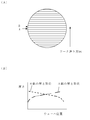
- the thickness shape of the cut wafer increases from the wire entry side to the removal side to the workpiece. It has a tapered shape, and the direction of the taper is a regular stepped shape that is inverted between a location where the wire is advanced and cut and a location where the wire is retracted and cut.
- FIG. 3A and 3B are diagrams schematically showing this state.
- FIG. 3A is a side view of the cut surface of the workpiece, and shows a case where the traveling direction of the wire is reversed between the cutting of the A part and the cutting of the B part.
- FIG. 3B is a diagram showing the relationship between the wafer position from the wire entry side and the thickness of the cut portion in the cutting of the A portion in this case.
- the thickness shapes of the A portion and the B portion are shapes obtained by inverting the taper shape as described above. Such a regular stepped shape of the wafer cut surface is fine, and when the cutting is continuously performed, the nanotopography inspection does not cause a defect.
- the inventor further studied and controlled the direction of reciprocation of the wire and the travel time in that direction so that the reciprocation cycle of the wire was continuous before and after the cutting of the workpiece was interrupted. By resuming the cutting, it is possible to suppress the deterioration of the nanotopography caused by the above causes and complete the cutting, and as a result, it is possible to prevent the failure in the nanotopography inspection.
- the present invention has been completed.
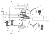
- FIG. 1 is a schematic view showing an example of the wire saw of the present invention.
- a wire saw 1 of the present invention mainly includes a wire 2 for cutting a workpiece W, a grooved roller 3, a wire tension applying mechanism 4, 4 ′ for applying tension to the wire 2,
- the workpiece feeding means 5 for relatively pushing down and feeding the workpiece W to be cut into a wafer shape, and the slurry supply means 6 for supplying a cutting slurry to the wire 2 at the time of cutting.
- the wire 2 is fed out from one wire reel 7 and enters a grooved roller 3 through a traverser and a wire tension applying mechanism 4 including a powder clutch (constant torque motor), a dancer roller (dead weight) and the like.
- a wire array is formed by winding the wire 2 around the plurality of grooved rollers 3 about 300 to 400 times.
- the wire 2 is wound around a wire reel 7 'through another wire tension applying mechanism 4'.
- the grooved roller 3 is a roller in which polyurethane resin is press-fitted around a steel cylinder and grooves are cut at a constant pitch on the surface thereof, and the wire 2 wound by the driving motor 10 is axially moved. It is possible to travel back and forth.
- the workpiece W is bonded to a backing plate, and is held by the workpiece feeding means 5 via a backing plate and a workpiece plate that holds the backing plate.
- the workpiece W is sent to the wire 2 positioned relatively below by the workpiece feeding means 5.
- the workpiece feeding means 5 pushes the workpiece W relatively downward until the wire 2 reaches the contact plate, thereby pushing the workpiece W against the reciprocating wire 2 and feeding it.
- the workpiece feeding means 5 can feed the workpiece W held at a feeding speed programmed in advance by computer control. Then, after the cutting of the workpiece W is completed, the cut workpiece W is pulled out from the wire row by reversing the feeding direction of the workpiece W.
- the slurry supply means 6 includes a slurry tank 11, a slurry chiller 12, a nozzle 13, and the like.
- the nozzle 13 is disposed above the wire 2 wound around the grooved roller 3.
- the nozzle 13 is connected to the slurry tank 11 via the slurry chiller 12, and the supply temperature of the cutting slurry supplied is controlled by the slurry chiller 12 and can be supplied from the nozzle 13 to the wire 2.
- the kind of slurry used during cutting is not particularly limited, and the same type as in the past can be used.
- GC silicon carbide
- abrasive grains can be dispersed in a liquid.
- the wire saw 1 of the present invention includes a wire travel history recording means 9 that detects the direction and travel speed of the wire 2 during the cutting of the workpiece W and records them in time series, and a wire A control device 8 is provided for controlling the reciprocating direction of the wire 2 and the traveling time and traveling speed in each direction so that the reciprocating device 2 reciprocates in a predetermined cycle.
- the wire travel history recording means 9 is connected to the control device 8, and the control device 8 reads the travel history of the wire 2 recorded in the wire travel history recording means 9 (travel direction, travel speed, etc. recorded in time series). Be able to.
- the wire saw 1 cuts the workpiece W while recording the reciprocating direction and traveling speed of the wire 2 in the wire travel history recording means 9 in time series while the workpiece W is being cut.
- the control device 8 restarts the reciprocation cycle of the wire 2 before and after the interruption of the workpiece W cutting. Based on the traveling history of the wire recorded by the wire traveling history recording means 9 until the interruption of the cutting of the work W, the direction of the reciprocating traveling of the wire 2 and the traveling time in that direction are recorded so as to be continuous later. Control.
- the reciprocating cycle of the wire can be controlled to be continuous with the cycle immediately before the cutting is interrupted.
- the cycle immediately before the cutting is interrupted means a cycle in which the predetermined advancement and retraction of the wire are completed without interrupting the traveling of the wire.
- the traveling time in the forward direction of the wire and the traveling time in the backward direction are the same as the cycle immediately before interrupting the cutting. Means.
- the wire stops at the point where the traveling in the forward direction is just finished, it starts from the point where the traveling in the backward direction starts. Further, for example, when the wire stops traveling in the forward direction for half of the predetermined time, after the resumption, the wire travels in the forward direction for the remaining half of the time and then in the backward direction. Just drive.
- a wire saw even when resuming cutting of a workpiece that has been interrupted due to an abnormality such as a broken wire, the step shape of the work cutting surface is discontinuous before and after resuming cutting of the workpiece. Therefore, it is possible to complete the cutting while suppressing the deterioration of the nanotopography of the processed wafer, and as a result, it is possible to prevent a failure in the nanotopography inspection.
- a temperature adjustment medium supply unit 16 for supplying a temperature adjustment medium whose temperature is controlled independently to the grooved roller 3 and the workpiece W is provided, and by this temperature adjustment medium supply unit 16, Before restarting the cutting of the workpiece, by supplying a temperature adjusting medium, the axial displacement amount of the grooved roller 3 and the temperature of the workpiece W are adjusted to be the same as when the cutting of the workpiece is interrupted. It is preferable to configure.
- the wire saw 20 shown in FIG. 2 measures and records the temperature of the workpiece W being cut, for example, a workpiece temperature recording means 14 having a radiation thermometer and the axial displacement of the grooved roller 3.
- Displacement amount recording means 15 having, for example, an eddy current displacement sensor or the like for measuring and recording the amount is provided. These recording means 14 and 15 can record the amount of axial displacement of the grooved roller 3 and the temperature of the workpiece W when the cutting of the workpiece is interrupted.
- the state of thermal expansion between the grooved roller and the workpiece does not become discontinuous before and after the cutting is interrupted, and a step is generated on the surface of the cut wafer, or the nanotopology is generated.
- the cutting of the workpiece can be completed while suppressing the deterioration of the graphic.
- the control of adjusting the axial displacement amount of the grooved roller and the temperature of the workpiece when resuming the cutting of the workpiece is performed as shown in FIG. It may be configured to be performed by the control device 8 that controls the travel time and the travel speed, or may be performed by a control device provided separately.
- FIG. 2 shows an example in which the temperature adjustment medium is supplied to the grooved roller 3 of the temperature adjustment medium supply means 16 by using the same slurry tank 11 and slurry chiller 12 as the slurry supply means 6.
- a temperature-controlled gas can be used as a temperature adjustment medium for the workpiece W.
- tension is applied to the wire 2 to reciprocate in the axial direction, and in a state where the slurry is supplied to the wire 2, the workpiece W held by the workpiece feeding means 5 is relatively pushed down to move the workpiece W.
- the workpiece W is cut by being pressed against the reciprocating wire 2 and cut. Further, the direction and traveling speed of the wire 2 reciprocating while the workpiece W is being cut are detected and recorded in the wire travel history recording means 9 in time series.
- the cause of the interruption is removed and a recovery operation is performed. For example, when the wire 2 is disconnected, a repair work for the wire 2 is performed, and then a recovery operation for engaging each notch of the workpiece with each row of the wire row is performed.
- the reciprocating cycle of the wire is continuous before and after resuming the cutting of the workpiece, and the traveling in that direction
- the time is controlled by the control device 8 based on the wire travel history recorded up to the time when the cutting of the workpiece is interrupted, and the cutting is resumed.
- the reciprocating cycle of the wire can be controlled to be continuous with the cycle immediately before the cutting is interrupted.
- the cycle immediately before the cutting is interrupted means a cycle in which the predetermined advancement and retraction of the wire are completed without interrupting the traveling of the wire.
- the traveling time in the forward direction of the wire and the traveling time in the backward direction are the same as the cycle immediately before interrupting the cutting. Means.
- the wire stops at the point where the traveling in the forward direction is just finished it starts from the point where the traveling in the backward direction starts. Further, for example, when the wire stops traveling in the forward direction for half of the predetermined time, after the resumption, the wire travels in the forward direction for the remaining half of the time and then in the backward direction. Just drive.
- the axial displacement amount of the grooved roller and the temperature of the workpiece are adjusted to be the same as when the workpiece cutting is interrupted. It is preferable. In this way, the state of thermal expansion between the grooved roller and the workpiece does not become discontinuous before and after the cutting is interrupted, and a step is generated on the surface of the cut wafer, or the nanotopology is generated. The cutting of the workpiece can be completed while suppressing the deterioration of the graphic.
- Example 1-3 Using the wire saw of the present invention as shown in FIG. 1, a silicon ingot having a diameter of 300 mm was started to be cut into a wafer, and the cutting was interrupted midway, and the cutting was resumed according to the operation restarting method of the present invention. Then, the nanotopography of the wafer after cutting was evaluated. Here, the maximum value of nanotopography in the 10 mm ⁇ 10 mm region measured in the region near the cutting interruption position was evaluated.
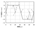
- the wire was run with the running speed profile shown in FIG. 4 while the workpiece was being cut.
- This travel speed profile has a travel cycle in which the wire starts traveling in the forward direction from the time indicated by 0, decelerates at a constant acceleration from the time indicated by B, and starts to travel in the backward direction from the time indicated by B ′. Is.
- the silicon ingot was cut to a central position (cut depth: 150 mm) while detecting and recording the direction and speed of the wire reciprocating. Therefore, the processing was temporarily interrupted, and the silicon ingot was raised and removed from the wire row. Thereafter, the silicon ingot was lowered again, the silicon ingot was returned to the position where the cutting was interrupted, and the cutting was resumed.
- the timing for interrupting the cutting was set at positions A, B, and C of the traveling speed profile shown in FIG. 4, and the wire stopped at the time of each traveling cycle of A ′, B ′, and C ′.
- the present invention is not limited to the above embodiment.
- the above-described embodiment is an exemplification, and the present invention has any configuration that has substantially the same configuration as the technical idea described in the claims of the present invention and exhibits the same function and effect. Are included in the technical scope.
Landscapes
- Engineering & Computer Science (AREA)
- Mechanical Engineering (AREA)
- Finish Polishing, Edge Sharpening, And Grinding By Specific Grinding Devices (AREA)
- Mechanical Treatment Of Semiconductor (AREA)
- Processing Of Stones Or Stones Resemblance Materials (AREA)
Abstract
Description
この方法及び装置によれば、ワイヤ補修処理に長時間を要した場合でも溝付きローラの収縮やワークの収縮に起因したウェーハ表面の段差発生を回避することができる。
本発明はこのような問題に鑑みてなされたもので、ワイヤソーによるワークの切断において、ワイヤの断線等の異常によって途中で中断されたワークの切断を再開する場合でも、加工後のウェーハのナノトポグラフィーの悪化を確実に抑制して切断を完了させることができ、ナノトポグラフィー検査で不良となるのを防ぐことができるワイヤソーの運転再開方法及びそのワイヤソーを提供することを目的とする。
このようにすれば、溝付きローラの収縮やワークの収縮に起因したウェーハ切断面の段差発生を回避することができ、ナノトポグラフィーの悪化をより効果的に抑制することができる。
このようなものであれば、溝付きローラの収縮やワークの収縮に起因したウェーハ表面の段差発生を回避することができ、ナノトポグラフィーの悪化をより効果的に抑制することができる。
従来、ワイヤソーによるワークの切断において、ワイヤの断線等の異常によってワークの切断が途中で中断された場合にワークの切断を再開すると、ウェーハ切断面に修正不能な段差が発生するという問題に対し、溝付きローラとワークにそれぞれ独立に温度制御した温度調整媒体を供給することによって、溝付きローラの軸方向の変位量とワークの温度をワークの切断を中断した時と同じに調整した後、切断を再開する方法が知られている。
このようなウェーハ切断面の規則的な段差形状は微細であり、切断が連続的に行われる場合にはナノトポグラフィー検査で不良となることはない。
図1に示すように、本発明のワイヤソー1は、主に、ワークWを切断するためのワイヤ2、溝付きローラ3、ワイヤ2に張力を付与するためのワイヤ張力付与機構4、4’、ウェーハ状に切断されるワークWを相対的に押し下げて切り込み送りするワーク送り手段5、切断時にワイヤ2に切断用のスラリを供給するためのスラリ供給手段6等で構成されている。
ワークWは当て板に接着されており、当て板とこの当て板を保持するワークプレートを介して、ワーク送り手段5により保持される。
ここで、切断中に使用するスラリの種類は特に限定されず、従来と同様のものを用いることができ、例えばGC(炭化珪素)砥粒を液体に分散させたものとすることができる。
このワイヤ走行履歴記録手段9は制御装置8と接続されており、制御装置8はワイヤ走行履歴記録手段9に記録したワイヤ2の走行履歴(時系列で記録した走行方向、走行速度など)を読み取ることができるようになっている。
さらに、例えば、ワイヤが前進方向への走行を、あらかじめ決められた時間の1/2走行したところで停止した場合には、再開後に前進方向へ残りの1/2の時間走行した後、後退方向へ走行すればよい。
このようなワイヤソーであれば、ワイヤの断線等の異常によって途中で中断されたワークの切断を再開する場合でも、ワークの切断面の段差形状がワークの切断の中断前と再開後とで不連続になることがなく、加工後のウェーハのナノトポグラフィーの悪化を抑制して切断を完了させることができ、その結果、ナノトポグラフィー検査で不良となるのを防ぐことができる。
この図2に示すワイヤソー20は切断中のワークWの温度を測定して記録するための、例えば放射式温度計等を有したワーク温度の記録手段14と、溝付きローラ3の軸方向の変位量を測定して記録するための、例えば渦電流式変位センサ等を有した変位量の記録手段15とを備えている。これらの記録手段14、15によってワークの切断の中断時の溝付きローラ3の軸方向の変位量とワークWの温度を記録しておくことができる。
このようなワークの切断の再開時における溝付きローラの軸方向の変位量とワークの温度の調整の制御は、図2に示すように、上記したワイヤの往復走行の方向と、各方向への走行時間及び走行速度を制御する制御装置8によって行うように構成しても良いし、これとは別に設けた制御装置によって行っても良い。
或いは、ワークWへの温度調整媒体として温度制御された気体を用いることもできる。
ここでは、図1に示す本発明のワイヤソーを用いた場合について説明する。
前提として、ワークWの切断を行うために、まず、ワークWに当て板を接着し、該当て板をワークプレートにより保持する。そして、これらの当て板、ワークプレートを介してワーク送り手段5によりワークWを保持する。
また、ワークWの切断中にワイヤ2の往復走行の方向及び走行速度を検出してワイヤ走行履歴記録手段9に時系列で記録する。
そして、例えばワイヤの断線等の異常の発生によりワークの切断を中断し、その切断を再開する際、まず、切断の中断の原因を除去し復旧作業を行う。例えばワイヤ2の断線が発生した場合には、ワイヤ2の補修作業を行い、その後、ワイヤ列の各列に対してワークの各切込みを対応させて係合させる復旧作業を行う。
この際、ワイヤの往復サイクルが切断を中断する直前のサイクルと連続的になるように制御することができる。ここで、切断を中断する直前のサイクルとは、ワイヤの走行を中断することなく、あらかじめ決められたワイヤの前進及び後退を完結したサイクルを意味し、連続的になるように制御するとは、ワイヤの往復サイクル中にワークWの切断を中断して、その後再開したサイクルにおいて、ワイヤの前進方向への走行時間と、後退方向への走行時間が、切断を中断する直前のサイクルと同じであることを意味する。
さらに、例えば、ワイヤが前進方向への走行を、あらかじめ決められた時間の1/2走行したところで停止した場合には、再開後に前進方向へ残りの1/2の時間走行した後、後退方向へ走行すればよい。
このようにすれば、溝付きローラとワークの熱膨張の状態が、切断を中断する前と再開した後とで不連続になることがなく、切断したウェーハの表面に段差が生じたり、ナノトポグラフィーが悪化するのを抑制しつつワークの切断を完了することができる。
(実施例1-3)
図1に示すような本発明のワイヤソーを用い、直径300mmのシリコンインゴットをウェーハ状に切断を開始し、その途中で切断を中断し、本発明の運転再開方法に従って切断を再開した。そして、切断後のウェーハのナノトポグラフィーを評価した。ここでは、切断中断位置付近の領域で測定された10mm×10mm領域におけるナノトポグラフィーの最大値を評価した。
このように、本発明のワイヤソー及びワイヤソーの運転再開方法は、ワークの切断が途中で中断された場合でも、加工後のウェーハのナノトポグラフィーの悪化を抑制して切断を完了させることができ、ナノトポグラフィー検査で不良となるのを防ぐことができることが確認できた。
本発明の制御装置を具備しない従来のワイヤソーを用い、切断を中断するタイミングを、図4に示す走行速度プロファイルのA(比較例1)、B(比較例2)、C(比較例3)の位置とし、切断の再開を切断中断位置と関係なく0の時点とした以外、すなわち、ワークの切断を再開する際にワイヤの往復走行の方向及びその方向への走行時間を制御しなかった以外、実施例1-3と同様な条件でシリコンインゴットを切断し、切断後のウェーハのナノトポグラフィーを評価した。
その結果を表1に示す。表1に示すように、比較例1-3共に実施例1-3の結果と比べ悪化しており、ナノトポグラフィー検査で不良となってしまった。

Claims (4)
- 複数の溝付きローラに巻掛けられたワイヤを軸方向に所定のサイクルで往復走行させ、前記ワイヤに切断用のスラリを供給しつつ、ワークを相対的に押し下げて、前記往復走行するワイヤに押し当てて切り込み送りし、前記ワークをウェーハ状に切断するワイヤソーの運転において、前記ワークの切断を途中で一旦中断した後、該切断を再開する場合の運転再開方法であって、
前記ワイヤの往復走行の方向及び走行速度を検出して時系列で記録しつつ前記ワークを切断する工程と、
前記ワークの切断を再開する際に、前記ワイヤの往復サイクルが前記ワークの切断の中断前と再開後で連続的となるように、前記ワイヤの往復走行の方向及びその方向への走行時間を前記ワークの切断の中断時までに記録されたワイヤの走行履歴に基づいて制御して切断を再開する工程とを有することを特徴とするワイヤソーの運転再開方法。 - 前記ワークの切断を再開する前に、温度調整媒体を供給することによって前記溝付きローラの軸方向の変位量と前記ワークの温度を前記ワークの切断の中断時とそれぞれ同じになるように調整することを特徴とする請求項1に記載のワイヤソーの運転再開方法。
- 複数の溝付きローラに巻掛けられ、軸方向に往復走行するワイヤと、該ワイヤに切断用のスラリを供給するスラリ供給手段と、ウェーハ状に切断されるワークを相対的に押し下げて、前記往復走行するワイヤに押し当てて切り込み送りするワーク送り手段とを具備するワイヤソーであって、
更に、前記ワークの切断中に前記ワイヤの往復走行の方向と走行速度を検出して時系列で記録するワイヤ走行履歴記録手段と、前記ワイヤが所定のサイクルで往復走行するように、前記ワイヤの往復走行の方向と、各方向への走行時間及び走行速度を制御する制御装置とを具備し、
前記ワークの切断を途中で一旦中断した後、前記ワークの切断を再開する際、前記制御装置は前記ワイヤの往復サイクルが前記ワークの切断の中断前と再開後で連続的となるように、前記ワイヤの往復走行の方向及びその方向への走行時間を前記ワイヤ走行履歴記録手段によって前記ワークの切断の中断時までに記録されたワイヤの走行履歴に基づいて制御するものであることを特徴とするワイヤソー。 - 更に、前記溝付きローラと前記ワークにそれぞれ独立に温度制御した温度調整媒体を供給する温度調整媒体供給手段を有し、該温度調整媒体供給手段は、前記ワークの切断を再開する前に、前記温度調整媒体を供給することによって前記溝付きローラの軸方向の変位量と前記ワークの温度を前記ワークの切断の中断時とそれぞれ同じになるように調整するものであることを特徴とする請求項3に記載のワイヤソー。
Priority Applications (5)
| Application Number | Priority Date | Filing Date | Title |
|---|---|---|---|
| SG2013069042A SG193449A1 (en) | 2011-04-20 | 2012-04-02 | Method for resuming operation of wire saw and wire saw |
| US14/004,791 US9079332B2 (en) | 2011-04-20 | 2012-04-02 | Method for resuming operation of wire saw and wire saw |
| KR1020137024928A KR101846933B1 (ko) | 2011-04-20 | 2012-04-02 | 와이어 쏘의 운전 재개 방법 및 와이어 쏘 |
| DE112012001312.3T DE112012001312B4 (de) | 2011-04-20 | 2012-04-02 | Verfahren zur Wiederaufnahme des Betriebs einer Drahtsäge und Drahtsäge |
| CN201280018787.3A CN103687697B (zh) | 2011-04-20 | 2012-04-02 | 线锯的再次开始运转方法及线锯 |
Applications Claiming Priority (2)
| Application Number | Priority Date | Filing Date | Title |
|---|---|---|---|
| JP2011-094357 | 2011-04-20 | ||
| JP2011094357A JP5494558B2 (ja) | 2011-04-20 | 2011-04-20 | ワイヤソーの運転再開方法及びワイヤソー |
Publications (1)
| Publication Number | Publication Date |
|---|---|
| WO2012144136A1 true WO2012144136A1 (ja) | 2012-10-26 |
Family
ID=47041273
Family Applications (1)
| Application Number | Title | Priority Date | Filing Date |
|---|---|---|---|
| PCT/JP2012/002276 Ceased WO2012144136A1 (ja) | 2011-04-20 | 2012-04-02 | ワイヤソーの運転再開方法及びワイヤソー |
Country Status (7)
| Country | Link |
|---|---|
| US (1) | US9079332B2 (ja) |
| JP (1) | JP5494558B2 (ja) |
| KR (1) | KR101846933B1 (ja) |
| CN (1) | CN103687697B (ja) |
| DE (1) | DE112012001312B4 (ja) |
| SG (1) | SG193449A1 (ja) |
| WO (1) | WO2012144136A1 (ja) |
Cited By (2)
| Publication number | Priority date | Publication date | Assignee | Title |
|---|---|---|---|---|
| CN103847035A (zh) * | 2012-11-29 | 2014-06-11 | 硅电子股份公司 | 用于在意外中断之后恢复工件的线锯过程的方法 |
| CN111319148A (zh) * | 2018-12-17 | 2020-06-23 | 硅电子股份公司 | 借助于线锯制造半导体晶片的方法、线锯以及单晶硅半导体晶片 |
Families Citing this family (13)
| Publication number | Priority date | Publication date | Assignee | Title |
|---|---|---|---|---|
| US20130144421A1 (en) * | 2011-12-01 | 2013-06-06 | Memc Electronic Materials, Spa | Systems For Controlling Temperature Of Bearings In A Wire Saw |
| JP5791642B2 (ja) * | 2013-01-10 | 2015-10-07 | 信越半導体株式会社 | ワイヤソーの運転再開方法 |
| JP6015598B2 (ja) * | 2013-08-28 | 2016-10-26 | 信越半導体株式会社 | インゴットの切断方法及びワイヤソー |
| JP6080753B2 (ja) * | 2013-12-13 | 2017-02-15 | 信越半導体株式会社 | ワイヤソーの運転再開方法 |
| CN105082380B (zh) * | 2015-09-09 | 2016-09-07 | 江西赛维Ldk太阳能高科技有限公司 | 硅片切割后的取出方法 |
| US10448453B2 (en) * | 2015-09-25 | 2019-10-15 | Intel Corporation | Virtual sensor system |
| CN109153104B (zh) * | 2016-07-13 | 2021-03-16 | 信越半导体株式会社 | 线锯装置及工件的切断方法 |
| CA3097322A1 (en) | 2018-04-23 | 2019-10-31 | Mitsubishi Chemical Corporation | Epoxy resin composition for carbon-fiber-reinforced composite materials, prepreg, and carbon-fiber-reinforced composite material |
| JP7020286B2 (ja) * | 2018-05-15 | 2022-02-16 | 信越半導体株式会社 | インゴットの切断方法及びワイヤーソー |
| KR102310452B1 (ko) * | 2018-10-05 | 2021-10-08 | 주식회사 엘지화학 | 도광판용 플라스틱 기판의 제조 방법 |
| CN112071765B (zh) * | 2020-08-18 | 2024-07-30 | 中环领先(徐州)半导体材料有限公司 | 确定晶圆加工参数的方法和晶圆的加工方法 |
| CN112008217A (zh) * | 2020-09-03 | 2020-12-01 | 烟台大东钢板有限公司 | 数控等离子切割机的控制方法及装置 |
| CN115674468B (zh) * | 2022-08-31 | 2025-09-05 | 麦斯克电子材料股份有限公司 | 一种8吋半导体硅晶棒金刚线切割断线后复切工艺 |
Citations (4)
| Publication number | Priority date | Publication date | Assignee | Title |
|---|---|---|---|---|
| JPH106202A (ja) * | 1996-06-27 | 1998-01-13 | Nippei Toyama Corp | ワイヤソー及びその切断停止制御方法 |
| JPH10202497A (ja) * | 1997-01-13 | 1998-08-04 | Shin Etsu Handotai Co Ltd | 半導体スライス装置のワイヤ切断時の運転再開方法及びその装置 |
| JP2009090377A (ja) * | 2007-10-03 | 2009-04-30 | Denso Corp | 炭化珪素基板製造用ワイヤーソー装置 |
| JP2010029955A (ja) * | 2008-07-25 | 2010-02-12 | Shin Etsu Handotai Co Ltd | ワイヤソーの運転再開方法及びワイヤソー |
Family Cites Families (12)
| Publication number | Priority date | Publication date | Assignee | Title |
|---|---|---|---|---|
| CN86101982B (zh) * | 1986-03-27 | 1987-11-25 | 北京工业大学 | 汉字问答式线切割编程及控制机 |
| JP2870452B2 (ja) * | 1995-05-31 | 1999-03-17 | 信越半導体株式会社 | ワイヤソー |
| JPH10249700A (ja) * | 1997-03-17 | 1998-09-22 | Super Silicon Kenkyusho:Kk | ワイヤソーによるインゴットの切断方法及び装置 |
| JP3731864B2 (ja) * | 2000-11-22 | 2006-01-05 | 株式会社タカトリ | ワイヤーソーにおけるワイヤー走行制御方法 |
| JP4129716B2 (ja) | 2001-03-30 | 2008-08-06 | 株式会社Sumco | ワイヤソー用ガイドローラ |
| JP4791306B2 (ja) * | 2006-09-22 | 2011-10-12 | 信越半導体株式会社 | 切断方法 |
| JP4816511B2 (ja) * | 2007-03-06 | 2011-11-16 | 信越半導体株式会社 | 切断方法およびワイヤソー装置 |
| JP5003294B2 (ja) * | 2007-06-08 | 2012-08-15 | 信越半導体株式会社 | 切断方法 |
| JP5177701B2 (ja) * | 2009-02-16 | 2013-04-10 | コマツNtc株式会社 | トラバース制御方法およびその装置 |
| CN101596750A (zh) * | 2009-04-21 | 2009-12-09 | 新乡市华盛天龙数控设备有限公司 | 多线切割机钢线收、放线自动跟踪控制方法及装置 |
| US8881716B2 (en) * | 2010-02-08 | 2014-11-11 | Toyo Advanced Technologies Co., Ltd. | Wire saw with tension detecting means and guide roller speed control |
| DE102012209974B4 (de) * | 2012-06-14 | 2018-02-15 | Siltronic Ag | Verfahren zum gleichzeitigen Abtrennen einer Vielzahl von Scheiben von einem zylindrischen Werkstück |
-
2011
- 2011-04-20 JP JP2011094357A patent/JP5494558B2/ja active Active
-
2012
- 2012-04-02 SG SG2013069042A patent/SG193449A1/en unknown
- 2012-04-02 KR KR1020137024928A patent/KR101846933B1/ko active Active
- 2012-04-02 DE DE112012001312.3T patent/DE112012001312B4/de active Active
- 2012-04-02 CN CN201280018787.3A patent/CN103687697B/zh active Active
- 2012-04-02 US US14/004,791 patent/US9079332B2/en active Active
- 2012-04-02 WO PCT/JP2012/002276 patent/WO2012144136A1/ja not_active Ceased
Patent Citations (4)
| Publication number | Priority date | Publication date | Assignee | Title |
|---|---|---|---|---|
| JPH106202A (ja) * | 1996-06-27 | 1998-01-13 | Nippei Toyama Corp | ワイヤソー及びその切断停止制御方法 |
| JPH10202497A (ja) * | 1997-01-13 | 1998-08-04 | Shin Etsu Handotai Co Ltd | 半導体スライス装置のワイヤ切断時の運転再開方法及びその装置 |
| JP2009090377A (ja) * | 2007-10-03 | 2009-04-30 | Denso Corp | 炭化珪素基板製造用ワイヤーソー装置 |
| JP2010029955A (ja) * | 2008-07-25 | 2010-02-12 | Shin Etsu Handotai Co Ltd | ワイヤソーの運転再開方法及びワイヤソー |
Cited By (3)
| Publication number | Priority date | Publication date | Assignee | Title |
|---|---|---|---|---|
| CN103847035A (zh) * | 2012-11-29 | 2014-06-11 | 硅电子股份公司 | 用于在意外中断之后恢复工件的线锯过程的方法 |
| CN103847035B (zh) * | 2012-11-29 | 2016-04-06 | 硅电子股份公司 | 用于在意外中断之后恢复工件的线锯锯切过程的方法 |
| CN111319148A (zh) * | 2018-12-17 | 2020-06-23 | 硅电子股份公司 | 借助于线锯制造半导体晶片的方法、线锯以及单晶硅半导体晶片 |
Also Published As
| Publication number | Publication date |
|---|---|
| JP5494558B2 (ja) | 2014-05-14 |
| KR101846933B1 (ko) | 2018-04-10 |
| CN103687697A (zh) | 2014-03-26 |
| JP2012223862A (ja) | 2012-11-15 |
| DE112012001312B4 (de) | 2019-12-24 |
| KR20140023287A (ko) | 2014-02-26 |
| US9079332B2 (en) | 2015-07-14 |
| SG193449A1 (en) | 2013-10-30 |
| US20140000580A1 (en) | 2014-01-02 |
| DE112012001312T5 (de) | 2014-01-02 |
| CN103687697B (zh) | 2016-03-16 |
Similar Documents
| Publication | Publication Date | Title |
|---|---|---|
| JP5494558B2 (ja) | ワイヤソーの運転再開方法及びワイヤソー | |
| JP5056859B2 (ja) | ワイヤソーによるワークの切断方法およびワイヤソー | |
| TWI413558B (zh) | Cutting method and wire saw using wire saw | |
| WO2010010657A1 (ja) | ワイヤソーの運転再開方法及びワイヤソー | |
| JP5791642B2 (ja) | ワイヤソーの運転再開方法 | |
| KR102545544B1 (ko) | 워크의 절단방법 및 와이어소 | |
| JP2010029955A5 (ja) | ||
| JP6015598B2 (ja) | インゴットの切断方法及びワイヤソー | |
| KR20140106583A (ko) | 워크의 절단방법 | |
| JP2008078473A (ja) | 切断方法 | |
| TWI568558B (zh) | Workpiece cutting method | |
| JP2009184023A (ja) | ワイヤソーによるワーク切断方法及びワイヤソー切断装置 | |
| JP2015112701A (ja) | ワイヤソーの運転再開方法 | |
| CN113710397A (zh) | 工件的切断方法及线锯 | |
| TW202327794A (zh) | 工件的切斷方法及線鋸 |
Legal Events
| Date | Code | Title | Description |
|---|---|---|---|
| WWE | Wipo information: entry into national phase |
Ref document number: 201280018787.3 Country of ref document: CN |
|
| 121 | Ep: the epo has been informed by wipo that ep was designated in this application |
Ref document number: 12774227 Country of ref document: EP Kind code of ref document: A1 |
|
| WWE | Wipo information: entry into national phase |
Ref document number: 14004791 Country of ref document: US |
|
| ENP | Entry into the national phase |
Ref document number: 20137024928 Country of ref document: KR Kind code of ref document: A |
|
| WWE | Wipo information: entry into national phase |
Ref document number: 112012001312 Country of ref document: DE Ref document number: 1120120013123 Country of ref document: DE |
|
| 122 | Ep: pct application non-entry in european phase |
Ref document number: 12774227 Country of ref document: EP Kind code of ref document: A1 |