WO2012144250A1 - Dispositif émetteur, procédé de transmission et support d'enregistrement - Google Patents
Dispositif émetteur, procédé de transmission et support d'enregistrement Download PDFInfo
- Publication number
- WO2012144250A1 WO2012144250A1 PCT/JP2012/052704 JP2012052704W WO2012144250A1 WO 2012144250 A1 WO2012144250 A1 WO 2012144250A1 JP 2012052704 W JP2012052704 W JP 2012052704W WO 2012144250 A1 WO2012144250 A1 WO 2012144250A1
- Authority
- WO
- WIPO (PCT)
- Prior art keywords
- image
- unit
- transmission
- hand
- size
- Prior art date
- Legal status (The legal status is an assumption and is not a legal conclusion. Google has not performed a legal analysis and makes no representation as to the accuracy of the status listed.)
- Ceased
Links
Images


Classifications
-
- G—PHYSICS
- G06—COMPUTING OR CALCULATING; COUNTING
- G06T—IMAGE DATA PROCESSING OR GENERATION, IN GENERAL
- G06T5/00—Image enhancement or restoration
- G06T5/50—Image enhancement or restoration using two or more images, e.g. averaging or subtraction
-
- H—ELECTRICITY
- H04—ELECTRIC COMMUNICATION TECHNIQUE
- H04N—PICTORIAL COMMUNICATION, e.g. TELEVISION
- H04N1/00—Scanning, transmission or reproduction of documents or the like, e.g. facsimile transmission; Details thereof
- H04N1/00127—Connection or combination of a still picture apparatus with another apparatus, e.g. for storage, processing or transmission of still picture signals or of information associated with a still picture
- H04N1/00132—Connection or combination of a still picture apparatus with another apparatus, e.g. for storage, processing or transmission of still picture signals or of information associated with a still picture in a digital photofinishing system, i.e. a system where digital photographic images undergo typical photofinishing processing, e.g. printing ordering
- H04N1/00137—Transmission
-
- H—ELECTRICITY
- H04—ELECTRIC COMMUNICATION TECHNIQUE
- H04N—PICTORIAL COMMUNICATION, e.g. TELEVISION
- H04N1/00—Scanning, transmission or reproduction of documents or the like, e.g. facsimile transmission; Details thereof
- H04N1/00127—Connection or combination of a still picture apparatus with another apparatus, e.g. for storage, processing or transmission of still picture signals or of information associated with a still picture
- H04N1/00132—Connection or combination of a still picture apparatus with another apparatus, e.g. for storage, processing or transmission of still picture signals or of information associated with a still picture in a digital photofinishing system, i.e. a system where digital photographic images undergo typical photofinishing processing, e.g. printing ordering
- H04N1/00167—Processing or editing
-
- H—ELECTRICITY
- H04—ELECTRIC COMMUNICATION TECHNIQUE
- H04N—PICTORIAL COMMUNICATION, e.g. TELEVISION
- H04N23/00—Cameras or camera modules comprising electronic image sensors; Control thereof
- H04N23/95—Computational photography systems, e.g. light-field imaging systems
-
- H—ELECTRICITY
- H04—ELECTRIC COMMUNICATION TECHNIQUE
- H04N—PICTORIAL COMMUNICATION, e.g. TELEVISION
- H04N25/00—Circuitry of solid-state image sensors [SSIS]; Control thereof
- H04N25/40—Extracting pixel data from image sensors by controlling scanning circuits, e.g. by modifying the number of pixels sampled or to be sampled
- H04N25/44—Extracting pixel data from image sensors by controlling scanning circuits, e.g. by modifying the number of pixels sampled or to be sampled by partially reading an SSIS array
- H04N25/443—Extracting pixel data from image sensors by controlling scanning circuits, e.g. by modifying the number of pixels sampled or to be sampled by partially reading an SSIS array by reading pixels from selected two-dimensional [2D] regions of the array, e.g. for windowing or digital zooming
-
- H—ELECTRICITY
- H04—ELECTRIC COMMUNICATION TECHNIQUE
- H04N—PICTORIAL COMMUNICATION, e.g. TELEVISION
- H04N5/00—Details of television systems
- H04N5/222—Studio circuitry; Studio devices; Studio equipment
- H04N5/262—Studio circuits, e.g. for mixing, switching-over, change of character of image, other special effects ; Cameras specially adapted for the electronic generation of special effects
- H04N5/2625—Studio circuits, e.g. for mixing, switching-over, change of character of image, other special effects ; Cameras specially adapted for the electronic generation of special effects for obtaining an image which is composed of images from a temporal image sequence, e.g. for a stroboscopic effect
-
- H—ELECTRICITY
- H04—ELECTRIC COMMUNICATION TECHNIQUE
- H04N—PICTORIAL COMMUNICATION, e.g. TELEVISION
- H04N2201/00—Indexing scheme relating to scanning, transmission or reproduction of documents or the like, and to details thereof
- H04N2201/0077—Types of the still picture apparatus
- H04N2201/0084—Digital still camera
-
- H—ELECTRICITY
- H04—ELECTRIC COMMUNICATION TECHNIQUE
- H04N—PICTORIAL COMMUNICATION, e.g. TELEVISION
- H04N2201/00—Indexing scheme relating to scanning, transmission or reproduction of documents or the like, and to details thereof
- H04N2201/0077—Types of the still picture apparatus
- H04N2201/0086—Image transceiver
-
- H—ELECTRICITY
- H04—ELECTRIC COMMUNICATION TECHNIQUE
- H04N—PICTORIAL COMMUNICATION, e.g. TELEVISION
- H04N5/00—Details of television systems
- H04N5/222—Studio circuitry; Studio devices; Studio equipment
- H04N5/262—Studio circuits, e.g. for mixing, switching-over, change of character of image, other special effects ; Cameras specially adapted for the electronic generation of special effects
-
- H—ELECTRICITY
- H04—ELECTRIC COMMUNICATION TECHNIQUE
- H04N—PICTORIAL COMMUNICATION, e.g. TELEVISION
- H04N7/00—Television systems
- H04N7/14—Systems for two-way working
- H04N7/141—Systems for two-way working between two video terminals, e.g. videophone
- H04N7/147—Communication arrangements, e.g. identifying the communication as a video-communication, intermediate storage of the signals
Definitions
- the present invention relates to a transmission device, a transmission method, and a recording medium, and more particularly, to a transmission device, a transmission method, and a recording medium for transmitting an image.
- Patent Document 1 describes a portable terminal with a videophone function that includes a first photographing lens and a second photographing lens.
- the portable terminal described in Patent Literature 1 combines an image of a landscape or an object in front of a user photographed with a first photographing lens and a user image photographed with a second photographing lens. Can be transmitted to the mobile terminal of the communication partner.
- Patent Literature 1 When the user A of the portable terminal described in Patent Literature 1 uses the portable terminal described in Patent Literature 1 to inform the user B of the portable terminal of the communication partner of the operation method of a certain device C, the user A While operating C, it is necessary to take a picture of itself and the operating location of device C.
- the user A serves as the subject, the photographer, and the operation explainer at the same time. Therefore, the burden on the user A is large, and either or all of the operation and shooting of the device C are likely to be insufficient, and it is difficult to sufficiently transmit information regarding the operation method of the device C. was there.
- An object of the present invention is to provide a transmission device, a transmission method, and a recording medium that can solve the above-described problems.
- the transmission apparatus includes a first imaging unit, a second imaging unit, an extraction unit that extracts a predetermined image from an image captured by the second imaging unit, and the first imaging unit A combining unit that generates a combined image by combining the extracted image and the predetermined image extracted by the extracting unit; and a transmitting unit that transmits the combined image.
- the transmission method of the present invention is a transmission method performed by a transmission apparatus including a first imaging unit and a second imaging unit, and an extraction step of extracting a predetermined image from an image captured by the second imaging unit And a synthesizing step for synthesizing the image photographed by the first photographing unit and the predetermined image to generate a synthesized image, and a transmitting step for transmitting the synthesized image.
- the recording medium of the present invention includes a computer, a first photographing unit, a second photographing unit, an extracting unit for extracting a predetermined image from an image photographed by the second photographing unit, and the first photographing unit.
- a computer-readable recording medium recording a program that functions as a combining unit that generates a combined image by combining the extracted image and the predetermined image extracted by the extracting unit, and a transmission unit that transmits the combined image .
- FIG. 1 is a plan view of an electronic device 1.
- FIG. 1 is a plan view of an electronic device 1.
- FIG. It is a flowchart for demonstrating the operation
- 6 is a diagram illustrating an example of a composite image output to a transmission control unit 17.
- FIG. 2 is a diagram illustrating an electronic apparatus 1 including an imaging unit 11, an imaging unit 12, an extraction unit 13, a synthesis unit 14, and a transmission control unit 17.
- FIG. 1 is a functional block diagram showing an electronic apparatus 1 which is an example of a transmission apparatus according to an embodiment of the present invention.
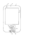
- FIG. 2A is a front view of the electronic device 1.
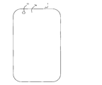
- FIG. 2B is a rear view of the electronic device 1.
- the electronic device 1 is, for example, a mobile phone or a smartphone.
- the electronic device 1 is not limited to a mobile phone or a smartphone, and may be, for example, a portable game machine, a tablet PC (Personal Computer), or a notebook PC.
- the electronic device 1 includes imaging units 11 and 12, an extraction unit 13, a synthesis unit 14, a display unit 15, a microphone 16, and a transmission control unit 17.
- the imaging unit 11 can be generally referred to as first imaging means.
- the imaging unit 11 is a camera and outputs a captured image.
- the captured image output from the imaging unit 11 is referred to as “captured image A”.
- the imaging unit 11 is provided on the back surface 1a of the electronic device 1 as illustrated in FIG. 2B.
- the imaging unit 12 can generally be referred to as second imaging means.
- the imaging unit 12 is a camera and outputs a captured image.
- the captured image output from the imaging unit 12 is referred to as “captured image B”.
- the imaging unit 12 is provided on the front surface 1b of the electronic device 1 as illustrated in FIG. 2A.
- the extraction unit 13 can be generally referred to as extraction means.
- the extraction unit 13 extracts an image of a human hand (hereinafter simply referred to as “hand image”) from the captured image B (an image captured by the imaging unit 12).
- the hand image can generally be referred to as a predetermined image.
- the predetermined image is not limited to the hand image and can be changed as appropriate.
- the extraction unit 13 includes a pattern DB (database) 13a and an image cutout processing unit 13b.
- the pattern DB 13a holds a hand pattern vector used to extract a hand image.
- the image cutout processing unit 13b discriminates a human hand from the photographed image B and extracts a hand image from the photographed image B by using an image recognition technique using a hand pattern vector in the pattern DB 13a.
- the synthesizing unit 14 can be generally referred to as synthesizing means.
- the synthesizing unit 14 synthesizes the captured image A (image captured by the image capturing unit 11) and the hand image extracted by the image cutout processing unit 13b to generate a composite image.
- the combining unit 14 includes a specifying unit 14a and a generating unit 14b.
- the designation unit 14a can be generally referred to as operation detection means.
- the designation unit 14a is, for example, a keypad composed of a plurality of key buttons.
- the designation unit 14a detects the user's position designation operation for designating the position PT of the hand image extracted by the image cutout processing unit 13b in the captured image A, and the hand extracted by the image cutout processing unit 13b.
- the user's size designation operation for designating the image size SZ is detected.
- the designation unit 14a stores basic position information indicating the default position DP of the hand image in the captured image A and basic size information indicating the default size DS of the hand image.
- the designation unit 14a includes an arrow key 21, an enter key 22, a cancel key 23, and a switching key 24, as shown in FIG. 2A.
- the arrow key 21 is used to move the position PT of the hand image in the photographed image A up and down, left and right, and to enlarge or reduce the size SZ of the hand image in the photographed image A.
- the user's size designation operation is detected.
- the determination key 22 detects the user's determination operation for determining the user's operation content.
- the cancel key 23 detects a user cancel operation for canceling the user operation content.
- the switching key 24 detects a user switching operation for switching the function of the arrow key 21 to movement or enlargement / reduction.
- the function of the arrow key 21 is set to move by default.
- the operation of the upward arrow key is a position designation operation for moving the position PT upward, and the operation of the downward arrow key lowers the position PT.
- the position specifying operation for moving to the left the operation of the left arrow key becomes the position specifying operation for moving the position PT to the left, and the operation of the right arrow key is the position for moving the position PT to the right Specify operation.
- the operation of the upward arrow key becomes a size designation operation for enlarging the size SZ, and the operation of the downward arrow key changes the size SZ.
- the generation unit 14b can be generally referred to as generation means.
- the generating unit 14b combines the hand image extracted by the image cutout processing unit 13b with the position PT in the captured image A specified by the position specifying operation to generate a combined image. Further, the generation unit 14b sets the size of the hand image in the composite image to the size SZ designated by the size designation operation.
- the generation unit 14b includes a video memory 14b1 and an image composition unit 14b2.
- the video memory 14b1 includes a background memory 14b1a and a composition memory 14b1b.
- the background memory 14b1a holds the captured image A.
- the compositing memory 14b1b holds the hand image extracted by the image cutout processing unit 13b.
- the image composition unit 14b2 generates a composite image by superimposing the hand image retained in the composition memory 14b1b with the size SZ on the position PT on the captured image A retained in the background memory 14b1a.
- the display unit 15 can be generally called display means.
- the display unit 15 displays the composite image generated by the image composition unit 14b2.
- the microphone 16 can be generally called sound detection means.
- the microphone 16 detects a sound and generates sound data corresponding to the sound.
- the transmission control unit 17 can generally be referred to as transmission means.
- the transmission control unit 17 transmits the sound data generated by the microphone 16 together with the synthesized image generated by the image synthesizing unit 14b2 to a communication device (for example, a mobile terminal device) that is a call partner.
- a communication device for example, a mobile terminal device
- the user of the electronic device 1 images the device for which the operation method is described by the imaging unit 11 and images himself / herself by the imaging unit 12.
- FIG. 3 is a flowchart for explaining the operation of extracting the hand image from the captured image B from the imaging unit 12.
- the image cutout processing unit 13b acquires the captured image B captured by the imaging unit 12 (step S31)
- the image cutout processing unit 13b extracts the edge of the object from the captured image B (step S32).
- the image cutout processing unit 13b extracts feature points in the edge image specified by the image in the range surrounded by the extracted edges (step S33), and generates a pattern vector from the feature points (step S33). S34).
- the image cutout processor 13b collates the hand pattern vector stored in the pattern DB 13a with the pattern vector generated in step S34 (step S35).
- step S36 If the hand pattern vector in the pattern DB 13a does not match the pattern vector generated in step S34 (step S36), the image cutout processing unit 13b returns the process to step S31.
- the image cutout processing unit 13b displays the image in the range surrounded by the extracted edges, that is, the hand image. Is cut out from the captured image B (step S37), and the extracted hand image is output to the compositing memory 14b1b (step S38).
- the image extraction processing unit 13b ends the hand image extraction operation.
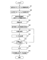
- FIG. 4 is a flowchart for explaining operations related to creation and transmission of image composition.
- the image combining unit 14b2 In a situation where the background memory 14b1a holds the captured image A output from the imaging unit 11, and the combining memory 14b1b holds the hand image output from the image cutout processing unit 13b, the image combining unit 14b2 The captured image A in the background memory 14b1a is acquired (step S41), and the hand image in the composition memory 14b1b is acquired (step S42).
- the image composition unit 14b2 acquires basic position information and basic size information in the designation unit 14a (step S43).
- the image composition unit 14b2 places the hand image in the composition memory 14b1b at the position designated by the basic size information at the position (default position DP) on the captured image A designated by the basic position information.
- a composite image is generated by superimposing (default size DS) (step S44).
- the image composition unit 14b2 displays the composite image on the display unit 15 (step S45).
- step S46 When changing the position of the hand image in the composite image, the user operates the arrow key 21 while confirming the composite image displayed on the display unit 15.
- the image composition unit 14b2 moves the position of the hand image in the composite image up and down and left and right according to the operation content of the arrow key 21, and displays the movement result on the display unit 15 (step S46). If the arrow key 21 is not operated, step S46 is omitted.
- the user When the user changes the size of the hand image in the composite image, the user first presses the switch key 24 to change the function of the arrow key 21 from “move” to “enlarge / reduce”, and then the arrow key 21 The key 21 is operated.
- Step S47 If the switching key 24 and the arrow key 21 are not operated, step S47 is omitted.
- steps S46 and S47 are executed until the enter key 22 is operated (step S48).
- the image composition unit 14b2 determines the position and size of the hand image in the composite image as being displayed on the display unit 15 (step S48), and the hand image. Is output to the transmission control unit 17 (step S49).
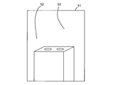
- FIG. 5 is a diagram illustrating an example of a composite image output to the transmission control unit 17.
- a composite image 51 is an image obtained by combining a hand image 53 on an image 52 that is a captured image A.
- the transmission control unit 17 synthesizes the synthesized image from the image synthesizing unit 14b2 and the sound data from the microphone 16 into a videophone format, and sends the synthesized result to the communication device that is the call partner (step S50). .
- the extraction unit 13 extracts a hand image from the captured image B of the imaging unit 12.
- the synthesizing unit 14 synthesizes the captured image A of the imaging unit 11 and the hand image extracted by the extracting unit 13 to generate a synthesized image.
- the transmission control unit 17 transmits the combined image generated by the combining unit 14.
- the imaging unit 11 captures a device for which an operation method is described and the imaging unit 12 captures a user, a composite image in which a hand image is combined with an image of the device captured by the imaging unit 11 is transmitted. Is done.
- the user can transmit an image indicating the operation position of the device by hand to the communication partner without taking an image of the device operating the device while operating the device. Further, for example, even for a device that is difficult to shoot while actually being operated (for example, a self-propelled device), an image showing the operation position of the device by hand can be transmitted to the communication partner.
- the user can easily obtain an image showing the operation position of the device by hand, that is, an image for explaining the operation method of the device, and the burden on the user can be reduced.
- the time required for transmitting the operation method of the device can be shortened, and thus the cost required for communication can be reduced.
- FIG. 6 is a diagram illustrating the electronic apparatus 1 including the imaging unit 11, the imaging unit 12, the extraction unit 13, the synthesis unit 14, and the transmission control unit 17.
- the designation unit 14a detects a position designation operation for designating the position of the hand image in the captured image A.
- the generation unit 14b generates a composite image by combining the hand image at the position specified by the position specifying operation in the captured image A.
- the user can set the position of the hand image in the captured image A to an arbitrary position.
- the designation unit 14a detects a size designation operation for designating the size of the hand image in the captured image A.
- the generation unit 14b sets the size of the hand image in the composite image to the size specified by the size specifying operation.
- the user can set the size of the hand image in the captured image A to an arbitrary size.
- the display unit 15 displays a composite image.
- the user can confirm the composite image to be transmitted. Further, the user can perform a position designation operation and a size designation operation while confirming the composite image displayed on the display unit 15, and appropriately set the position and size of the hand image in the captured image A. It becomes possible.
- the microphone 16 detects sound.
- the transmission control unit 17 transmits the sound detection result of the microphone 16 together with the synthesized image.
- the user can transmit the operation method of the device using sound in addition to the synthesized image.
- a hand image is used as the predetermined image.
- the hand can be changed into various forms according to the intention of the user, and is used when giving instructions or explanations even in daily life. For this reason, when a hand image is used as the predetermined image, a person who has seen the composite image is highly likely to intuitively pay attention to the target (device) indicated by the hand image. Therefore, it is possible to smoothly transmit the operation method of the device.
- the user when a speaker who is a user tries to transmit a device operation method using a videophone, the user can take a picture without difficulty, and a position designated by the hand image (for example, the device) Since the operation position can be easily confirmed and adjusted, an operation instruction can be transmitted to the call partner accurately and specifically.
- the hand image for example, the device
- the user uses the right hand to point to the location and operate the designation unit 14a using the left hand while holding the electronic device 1 with the left hand, or Operate with the right and left hands reversed.
- This embodiment may be modified as follows.
- an image clipping operation (hand image extracting operation) performed by the image clipping processing unit 13b and an image combining operation performed by the image combining unit 14b2 are continuously performed.
- the image composition unit 14b2 may change the position of the hand image in the captured image A in accordance with the change in the extraction position of the hand image from the captured image B.
- the image cutout processing unit 13b outputs the extraction position of the hand image from the captured image B to the image composition unit 14b2.
- the captured image A of the imaging unit 11 is used as the background image of the hand image, but the image transmitted from the other party by videophone as the background image of the hand image. (Received image) may be used. Further, as a background image of the hand image, a still image or a moving image stored in the electronic device 1 may be used.
- the hand image may be changed as appropriate.
- the image cutout processing unit 13b re-extracts the hand image, and the combined memory 14b1b Change the image of the hand inside.
- the user can indicate a fine place and direction with the image of the hand with one finger out, and can indicate a certain range with the image of the hand in the open state.
- the user can indicate the boundary with an image of a hand in a state where the palm is vertical. In this way, if the hand image is changed, it becomes possible to easily understand the instruction.
- the specifying unit 14a detects a user operation with a key button, but the specifying unit 14a may detect a user operation with another input unit such as a touch panel instead of the key button.
- the touch panel is arranged on the display unit 15, and on the captured image A displayed on the display unit 15 by an instruction unit such as a user's finger. The position of the hand image may be directly specified.
- the electronic device 1 may be realized by a computer.
- the computer reads and executes a program recorded on a recording medium such as a CD-ROM (Compact Disk Read Only Memory) that can be read by the computer, and the imaging units 11 and 12, the extraction unit 13, and the synthesis unit 14, functions as a display unit 15, a microphone 16, and a transmission control unit 17.
- a recording medium such as a CD-ROM (Compact Disk Read Only Memory) that can be read by the computer
- the recording medium is not limited to the CD-ROM and can be changed as appropriate.
- the electronic device 1 may be realized by a computer connected to the imaging units 11 and 12. In this case, the computer reads and executes the program recorded on the recording medium, and functions as the extraction unit 13, the synthesis unit 14, the display unit 15, the microphone 16, and the transmission control unit 17.
Landscapes
- Engineering & Computer Science (AREA)
- Multimedia (AREA)
- Signal Processing (AREA)
- Theoretical Computer Science (AREA)
- Computing Systems (AREA)
- Physics & Mathematics (AREA)
- General Physics & Mathematics (AREA)
- Telephone Function (AREA)
- Studio Devices (AREA)
- Two-Way Televisions, Distribution Of Moving Picture Or The Like (AREA)
Abstract
Priority Applications (3)
| Application Number | Priority Date | Filing Date | Title |
|---|---|---|---|
| EP12774187.4A EP2701378A1 (fr) | 2011-04-18 | 2012-02-07 | Dispositif émetteur, procédé de transmission et support d'enregistrement |
| US14/123,733 US20140198235A1 (en) | 2011-04-18 | 2012-02-07 | Transmission device, transmission method, and record medium |
| JP2013510906A JPWO2012144250A1 (ja) | 2011-04-18 | 2012-02-07 | 送信装置、送信方法および記録媒体 |
Applications Claiming Priority (2)
| Application Number | Priority Date | Filing Date | Title |
|---|---|---|---|
| JP2011092286 | 2011-04-18 | ||
| JP2011-092286 | 2011-04-18 |
Publications (1)
| Publication Number | Publication Date |
|---|---|
| WO2012144250A1 true WO2012144250A1 (fr) | 2012-10-26 |
Family
ID=47041375
Family Applications (1)
| Application Number | Title | Priority Date | Filing Date |
|---|---|---|---|
| PCT/JP2012/052704 Ceased WO2012144250A1 (fr) | 2011-04-18 | 2012-02-07 | Dispositif émetteur, procédé de transmission et support d'enregistrement |
Country Status (4)
| Country | Link |
|---|---|
| US (1) | US20140198235A1 (fr) |
| EP (1) | EP2701378A1 (fr) |
| JP (1) | JPWO2012144250A1 (fr) |
| WO (1) | WO2012144250A1 (fr) |
Citations (6)
| Publication number | Priority date | Publication date | Assignee | Title |
|---|---|---|---|---|
| JP2001169166A (ja) | 1999-12-14 | 2001-06-22 | Nec Corp | 携帯端末 |
| JP2003309829A (ja) * | 2002-04-15 | 2003-10-31 | Matsushita Electric Ind Co Ltd | 携帯動画電話装置 |
| JP2004120269A (ja) * | 2002-09-26 | 2004-04-15 | Fuji Photo Film Co Ltd | 携帯型撮像装置およびその制御方法 |
| JP2004147046A (ja) * | 2002-10-24 | 2004-05-20 | Matsushita Electric Ind Co Ltd | ディジタルカメラおよびディジタルカメラ付き携帯電話装置 |
| JP2005124161A (ja) * | 2003-09-25 | 2005-05-12 | Fuji Photo Film Co Ltd | テレビ電話機及びプログラム |
| JP2005204015A (ja) * | 2004-01-15 | 2005-07-28 | Nec Corp | 携帯機器および画像処理方法 |
Family Cites Families (2)
| Publication number | Priority date | Publication date | Assignee | Title |
|---|---|---|---|---|
| JP2003189168A (ja) * | 2001-12-21 | 2003-07-04 | Nec Corp | 携帯電話用カメラ |
| US7227567B1 (en) * | 2004-09-14 | 2007-06-05 | Avaya Technology Corp. | Customizable background for video communications |
-
2012
- 2012-02-07 JP JP2013510906A patent/JPWO2012144250A1/ja active Pending
- 2012-02-07 EP EP12774187.4A patent/EP2701378A1/fr not_active Withdrawn
- 2012-02-07 WO PCT/JP2012/052704 patent/WO2012144250A1/fr not_active Ceased
- 2012-02-07 US US14/123,733 patent/US20140198235A1/en not_active Abandoned
Patent Citations (6)
| Publication number | Priority date | Publication date | Assignee | Title |
|---|---|---|---|---|
| JP2001169166A (ja) | 1999-12-14 | 2001-06-22 | Nec Corp | 携帯端末 |
| JP2003309829A (ja) * | 2002-04-15 | 2003-10-31 | Matsushita Electric Ind Co Ltd | 携帯動画電話装置 |
| JP2004120269A (ja) * | 2002-09-26 | 2004-04-15 | Fuji Photo Film Co Ltd | 携帯型撮像装置およびその制御方法 |
| JP2004147046A (ja) * | 2002-10-24 | 2004-05-20 | Matsushita Electric Ind Co Ltd | ディジタルカメラおよびディジタルカメラ付き携帯電話装置 |
| JP2005124161A (ja) * | 2003-09-25 | 2005-05-12 | Fuji Photo Film Co Ltd | テレビ電話機及びプログラム |
| JP2005204015A (ja) * | 2004-01-15 | 2005-07-28 | Nec Corp | 携帯機器および画像処理方法 |
Also Published As
| Publication number | Publication date |
|---|---|
| US20140198235A1 (en) | 2014-07-17 |
| EP2701378A1 (fr) | 2014-02-26 |
| JPWO2012144250A1 (ja) | 2014-07-28 |
Similar Documents
| Publication | Publication Date | Title |
|---|---|---|
| US11696021B2 (en) | Video recording device and camera function control program | |
| US11099704B2 (en) | Mobile terminal and control method for displaying images from a camera on a touch screen of the mobile terminal | |
| KR102194094B1 (ko) | 가상과 실제 물체의 합성 방법, 장치, 프로그램 및 기록매체 | |
| JP7495517B2 (ja) | 画像撮影方法と電子機器 | |
| KR102114377B1 (ko) | 전자 장치에 의해 촬영된 이미지들을 프리뷰하는 방법 및 이를 위한 전자 장치 | |
| KR20190013308A (ko) | 이동 단말기 및 그 제어 방법 | |
| CN114327206A (zh) | 一种消息显示方法及电子设备 | |
| KR20140106779A (ko) | 이미지 촬영장치 및 방법 | |
| WO2017092128A1 (fr) | Procédé et dispositif pour afficher une image de prévisualisation | |
| US20090227283A1 (en) | Electronic device | |
| JP2005287004A (ja) | 画像表示方法、プログラム、画像表示装置及び画像表示システム | |
| CN103927165A (zh) | 一种壁纸图片的处理方法及装置 | |
| CN110196673B (zh) | 图片交互方法、装置、终端及存储介质 | |
| CN110300274A (zh) | 视频文件的录制方法、装置及存储介质 | |
| KR20160005305A (ko) | 이미지 절환 방법, 장치, 프로그램 및 기록매체 | |
| CN111586296A (zh) | 图像拍摄方法、图像拍摄装置及存储介质 | |
| CN114943791B (zh) | 动画播放方法、装置、设备及存储介质 | |
| CN116088976A (zh) | 文本朗读方法、装置、存储介质及电子设备 | |
| CN110086998A (zh) | 一种拍摄方法及终端 | |
| JP5749115B2 (ja) | 携帯端末装置、プログラムおよび電子文書作成方法 | |
| EP3916683A1 (fr) | Procédé et appareil d'affichage d'images, dispositif électronique et support d'enregistrement lisible par ordinateur | |
| KR20140130887A (ko) | 썸네일 이미지 생성 방법 및 그 전자 장치 | |
| CN104298442B (zh) | 一种信息处理方法及电子设备 | |
| CN117499750A (zh) | 评论发布方法、装置、终端及存储介质 | |
| CN113286073A (zh) | 拍摄方法、拍摄装置及存储介质 |
Legal Events
| Date | Code | Title | Description |
|---|---|---|---|
| 121 | Ep: the epo has been informed by wipo that ep was designated in this application |
Ref document number: 12774187 Country of ref document: EP Kind code of ref document: A1 |
|
| WWE | Wipo information: entry into national phase |
Ref document number: 2012774187 Country of ref document: EP |
|
| ENP | Entry into the national phase |
Ref document number: 2013510906 Country of ref document: JP Kind code of ref document: A |
|
| NENP | Non-entry into the national phase |
Ref country code: DE |
|
| WWE | Wipo information: entry into national phase |
Ref document number: 14123733 Country of ref document: US |