WO2012144259A1 - Appareil de formation d'image - Google Patents
Appareil de formation d'image Download PDFInfo
- Publication number
- WO2012144259A1 WO2012144259A1 PCT/JP2012/053872 JP2012053872W WO2012144259A1 WO 2012144259 A1 WO2012144259 A1 WO 2012144259A1 JP 2012053872 W JP2012053872 W JP 2012053872W WO 2012144259 A1 WO2012144259 A1 WO 2012144259A1
- Authority
- WO
- WIPO (PCT)
- Prior art keywords
- peeling claw
- photosensitive drum
- peeling
- recording medium
- tip
- Prior art date
- Legal status (The legal status is an assumption and is not a legal conclusion. Google has not performed a legal analysis and makes no representation as to the accuracy of the status listed.)
- Ceased
Links
Images


Classifications
-
- G—PHYSICS
- G03—PHOTOGRAPHY; CINEMATOGRAPHY; ANALOGOUS TECHNIQUES USING WAVES OTHER THAN OPTICAL WAVES; ELECTROGRAPHY; HOLOGRAPHY
- G03G—ELECTROGRAPHY; ELECTROPHOTOGRAPHY; MAGNETOGRAPHY
- G03G15/00—Apparatus for electrographic processes using a charge pattern
- G03G15/65—Apparatus which relate to the handling of copy material
- G03G15/6555—Handling of sheet copy material taking place in a specific part of the copy material feeding path
- G03G15/657—Feeding path after the transfer point and up to the fixing point, e.g. guides and feeding means for handling copy material carrying an unfused toner image
-
- G—PHYSICS
- G03—PHOTOGRAPHY; CINEMATOGRAPHY; ANALOGOUS TECHNIQUES USING WAVES OTHER THAN OPTICAL WAVES; ELECTROGRAPHY; HOLOGRAPHY
- G03G—ELECTROGRAPHY; ELECTROPHOTOGRAPHY; MAGNETOGRAPHY
- G03G2215/00—Apparatus for electrophotographic processes
- G03G2215/00362—Apparatus for electrophotographic processes relating to the copy medium handling
- G03G2215/00535—Stable handling of copy medium
- G03G2215/00556—Control of copy medium feeding
- G03G2215/00573—Recording medium stripping from image forming member
Definitions
- the present invention relates to an image forming apparatus.
- the present invention relates to an image forming apparatus having a peeling claw for peeling a recording medium from a photosensitive drum.
- An electrophotographic image forming apparatus is widely known. This image forming apparatus forms an electrostatic latent image on the surface of the photosensitive drum by light, adheres toner to the photosensitive drum along the electrostatic latent image, and transfers the adhered toner to a recording medium such as paper. The toner is fixed on the recording medium by a fixing device.
- the recording medium may not be peeled off while being adhered to the photosensitive drum due to charging.
- an image forming apparatus having a peeling claw for forcibly peeling a recording medium from a photosensitive drum is known.
- the peeling claw is constituted by a peeling claw body and a holding member, and the peeling claw body is swingably attached to the housing of the cleaning device via the holding member.
- the claw portion is attached to the surface of the photosensitive drum by the weight of the weight portion of the main body.
- the peeling claw has a weight structure with a pointed tip made of resin.
- the recording paper is peeled off by sharpening the tip and pushing the tip between the photosensitive drum and the recording paper.
- the peeling claw body is integrally molded from a resin material, and has a tapered claw portion at the front end and a weight portion at the rear end.
- the holding member is formed of a metal thin plate that can be elastically deformed, for example, even when a force is applied to the claw portion when removing a jammed paper around the photosensitive drum, the holding member is held.
- the member is elastically deformed according to this force, so that the paper can be easily removed and the claw portion is prevented from being damaged.
- An image forming apparatus having such a peeling claw is known.
- the peeling claw portion is brought into contact with the photosensitive drum by the weight of the weight portion around the shaft.
- the friction between the claw and the rotating portion of the holding portion is different for each peeling claw, and it is difficult to adjust the contact pressure of the plurality of peeling claws uniformly.
- the peeling claw it is necessary to adjust the method of applying to the photosensitive drum, and it takes a lot of time for manufacturing and maintenance.
- the peeling claw is a rigid body, and the peeling claw may be easily separated from the photosensitive drum due to external factors such as vibration of the device. If the leading edge of the recording paper passes with the peeling claw away from the photosensitive drum, paper jam occurs.
- the peeling claw In order to prevent the peeling claw from being separated, it is necessary to make strong contact with the photosensitive drum, which may damage the photosensitive drum. In addition, the structure of the peeling claw is complicated, the number of manufacturing and assembly steps is large, and workability is poor. In addition, since the tip of the peeling claw is sharpened and urged by a weight, when the recording paper is thin and strongly attached to the photosensitive drum, the peeling claw is affected by the impact of the peeling claw and the recording paper. If it floats even a little, the peeling claw may not sink under the recording paper and may cause a jam.
- the present invention solves such a problem and has a simple structure, but a plurality of peeling claws can be easily brought into contact with the photosensitive drum with a constant contact pressure, and the photosensitive drum is not damaged.
- An image forming apparatus capable of reliably peeling a recording medium from a photosensitive drum even when using the image forming apparatus is provided.
- the image forming apparatus of the present invention includes a photosensitive drum for attaching toner according to an electrostatic latent image formed on the surface, a transfer device for transferring the toner attached to the photosensitive drum to a recording medium, and a recording medium.
- a fixing device that fixes the transferred toner to the recording medium
- a peeling claw that peels off the recording medium attached to the photosensitive drum
- a peeling claw fixing frame that fixes the peeling claw.
- a peeling claw fixing plate made of a metal plate fixed between the peeling claw and the peeling claw fixing frame, the surface of the peeling claw being in contact with the photosensitive drum is formed so as to be gradually narrowed toward the tip, and has a thickness.
- the peeling claw is a portion formed gradually thinner and fixed to the peeling claw fixing plate except a part in the tip direction including the tip,
- the peeling claw fixing plate intersects the inclined portion formed gradually narrower toward the tip direction and the thickness direction of the peeling claw along the gradually narrowed side of the portion where the peeling claw is fixed.
- a convex portion that regulates movement in the direction, a portion of the peeling claw that is not fixed to the peeling claw fixing plate is curved so as to protrude toward the photosensitive drum, and the surface is in contact with the photosensitive drum.
- the structure is simple, a plurality of peeling claws can be easily brought into contact with the photosensitive drum with a constant contact pressure, and the photosensitive drum is not damaged and can be reliably used even with a thin recording medium. It can be peeled from the photosensitive drum.
- FIG. 1 is a schematic configuration diagram of an image forming apparatus.
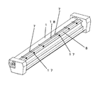
- FIG. 2 is a layout diagram of the peeling claws.
- FIG. 3 is a diagram illustrating the configuration of the peeling claw.
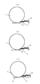
- FIG. 4 is a diagram for explaining how the recording medium is peeled from the photosensitive drum.
- FIG. 1 is a schematic configuration diagram of an image forming apparatus.
- the photosensitive drum 1 is a cylindrical rotating body. Toner is attached to the surface of the photosensitive drum 1 and the toner is transferred to the recording medium 4 being conveyed.
- the fixing device 11 includes a heating roller containing a heating element and a pressure roller that urges the heating roller, and fixes the toner on the recording medium 4 by heat and pressure.
- the photosensitive drum 1 forms an electrostatic latent image on the surface by the LED head 2, and a toner is adhered to the photosensitive drum 1 in correspondence with the electrostatic latent image by the developing device 3.
- the toner attached to the surface of the photosensitive drum 1 is attached to the recording medium 4 by the transfer device 9.
- the recording medium 4 is paper, film plastic, or the like.
- the recording medium 4 is transported to the fixing device 11 along the transport guide plate 12 by the transport roller 10.
- the conveyance roller 10 is composed of a rotating roller and a roller that is rotated by the roller, and conveys the recording medium 4 by the rotation of the roller.
- the toner is transferred to the recording medium 4 by the transfer device 9, but there is a slight amount of toner remaining.
- the toner remaining on the photosensitive drum 1 is removed by the cleaning unit 6 and further discharged. Thereafter, the surface of the photosensitive drum 1 is recharged by the charger 5, and an electrostatic latent image of a desired image is formed by the LED head 2.
- the recording medium 4 that has passed through the transfer device 9 is sometimes charged and transported without being peeled off from the photosensitive drum 1.
- the peeling claw 7 is a peeling claw fixing frame. 8 is fixed.
- the tip of the peeling claw 7 is in contact with the photosensitive drum 1.
- the recording medium 4 adheres to the photosensitive drum 1 and is conveyed, the recording medium 4 is peeled off from the photosensitive drum 1 by the peeling claw 7 and guided to the fixing device 11.
- a recess 18 is provided at the tip of the peeling claw fixing frame 8.
- the recesses 18 are provided to prevent the peeling claw fixing frame 8 from being distorted, and a plurality of the depressions 18 are arranged to facilitate adjustment of the contact pressure of the peeling claw 7 to the photosensitive drum 1.
- a peeling claw fixing plate 19 is fixed to the peeling claw fixing frame 8, and the peeling claw 7 is fixed to the peeling claw fixing plate 19.
- the peeling claw fixing plate 19 and the peeling claw 7 are fixed by an adhesive, an adhesive tape, or the like.
- the peeling claw fixing frame 8 is provided with a spur 17 so that the recording medium 4 does not hit the peeling claw 7 or the peeling claw fixing frame 8.
- the diameter of the photosensitive drum 1 is 60 mm.
- the difference 13 in the vertical direction between the lower end of the outer periphery of the photosensitive drum 1 and the separation claw 7 is not less than 2.4 mm and not more than 3.4 mm.
- the peeling claw 7 is arranged so as to be curved so that the tip contacts the photosensitive drum 1.
- a peeling claw position 16 indicated by a dotted line indicates a position when the photosensitive drum 1 is not present.
- the length 14 at which the peeling claw 7 overlaps the photosensitive drum 1 is 1.0 mm or more and 2.0 mm or less.
- the contact portion 15 is a protrusion provided to prevent the peeling claw 7 fixed to the peeling claw fixing frame 8 from moving due to an impact when it collides with the recording medium 4.
- the peeling claw 7 is disposed in parallel with the tangential direction of the lower end of the outer periphery of the photosensitive drum 1. This facilitates adjustment of the height from the lower end and the contact angle. This presses the tip of the peeling claw 7 against the photosensitive drum 1 against the vertical direction. The curvature of the peeling claw 7 increases as it goes to the tip.
- the peeling claw 7 is in contact with the photosensitive drum 1 at the surface. This is because the peeling claw 7 is a resin thin plate and is flexible to some extent, so that surface contact including the tip can be made. Since the surface is in contact with the photosensitive drum 1, the contact force is strong, and there is no rolling up at the time of collision with the recording medium 4. Further, the photosensitive drum 1 is not damaged.
- the peeling claw fixing frame 8 When the peeling claw fixing frame 8 is close to the photosensitive drum 1, the peeling claw 7 is greatly bent and the tip is separated from the photosensitive drum 1, which is not preferable.
- the vertical difference 13 between the lower end of the outer periphery of the photosensitive drum 1 and the separation claw 7 is large, the peeling claw 7 is curved and the tip is separated from the photosensitive drum 1, which is not preferable.
- the tip of the peeling claw 7 abuts on the photosensitive drum 1 so that the recording medium 4 does not enter the photosensitive drum 1.
- the position at which the peeling claw 7 is brought into contact with the photosensitive drum 1 is preferably in contact with the vertical direction from the center of the photosensitive drum 1 within an angle range of 15 degrees to 30 degrees. It is necessary to maintain a height at which the recording medium 4 can pass. Further, it is necessary to contact the photosensitive drum 1 with a predetermined length from the tip of the peeling claw 7, for example, 0.5 mm or more.
- the recess 18 is provided to increase the rigidity of the tip of the peeling claw fixing frame 8. This is to make it difficult to deform if a jam occurs. It is not preferable that the tip of the peeling claw fixing plate 19 is deformed in order to position the peeling claw 7. Moreover, since the peeling nail
- the peeling claw fixing plate 19 is made of a flat plate made of a metal plate such as AL or SUS having higher rigidity than the peeling claw 7.
- FIG. 2 is a layout diagram of the peeling nails.
- Six peeling claws 7 are arranged in the length direction of the photosensitive drum 1. They are arranged at equal intervals from the center toward the end.
- a spur 17 is disposed at a position corresponding to the peeling claw 7. Even if the width of the storage medium 4 to be used changes, it is arranged so that it can be peeled off at a plurality of at least two or more locations. For this reason, it is desired that the contact between each peeling claw 7 and the photosensitive drum 1 is equal.
- the peeling claw 7 can be attached to the peeling claw fixing frame 8 in the same manner, and the peeling claw 7 can be produced in large quantities with the same shape.
- each peeling claw 7 and the photosensitive drum 1 is easily the same. it can. Further, since all the peeling claws 7 are fixed to the peeling claw fixing frame 8, all the peeling claws 7 can be moved simultaneously by moving the peeling claw fixing plate 8. The separation / contact position between the peeling claw 7 and the photosensitive drum 1 can be easily adjusted.
- FIG. 3 is a diagram illustrating the configuration of the peeling claw.
- the peeling claw 7 is a flat thin plate made of resin.
- resin for example, engineering plastics such as PET and POM resin are particularly preferable because of excellent durability and the like.
- a resin such as PP may be used.
- a thin recording medium such as tressing paper
- the peeling claw 7 is fixed to the peeling claw fixing plate 19 leaving the tip.
- the fixing method is fixed by adhesion, welding or double-sided adhesive tape.
- the peeling claw fixing plate 19 and the peeling claw 7 are fixed at the overlapping portion.
- the peeling claw fixing plate is fixed to the peeling claw fixing frame 8 by adhesion, welding, double-sided adhesive tape, or the like. Since the peeling claw 7 is made of resin and the peeling claw fixing plate 19 is made of metal, the peeling claw fixing plate 19 has higher strength than the peeling claw 7.
- the tip of the peeling claw 7 is gradually narrowed toward the apex. It does not become thinner gradually in the thickness direction, but remains constant. It is preferable to configure so as not to deform in the thickness direction. There is a portion that does not overlap with the peeling claw fixing plate 19 in the direction from the top to the root of the peeling claw 7.
- the outer shape of the peeling claw fixing plate 19 is provided with an inclined portion that is slightly larger than the outer shape of the peeling claw 7 and narrows along a side that gradually becomes thinner toward the tip of the peeling claw 7. In order to maintain the flexibility of the peeling claw 7, the tip is not overlapped.
- the tip of the peeling claw 7 protrudes 8.0 mm from the base.
- the width of the base of the tip of the peeling claw 7 is 6.0 mm.
- the width of the portion where the peeling claw 7 is fixed to the peeling claw fixing plate 19 is 16.0 mm.
- the total length of the peeling claw 7 is 14.0 mm. These dimensions are preferably selected with a difference of about ⁇ 5 mm in accordance with the thickness of the recording medium 4 to be used, the positional relationship with the photosensitive drum 1 and the like.
- the peeling claw 7 by adjusting the peeling claw 7 to a shape that gradually becomes narrower toward the tip, it becomes easier to see when the peeling claw 7 is positioned, and the positioning can be easily performed. If it is a square plate that does not overlap only the tip, only the tip of the small peeling claw 7 is visible, and the adjustment work becomes difficult.
- the contact portion 15 is formed by forming a convex portion on the peeling claw fixing plate 19 by pressing.
- the peeling claw 7 is fixed to the peeling claw fixing plate 19, there is a possibility that the peeling claw 7 may move due to a collision with the recording medium 4, and is provided to prevent this. By moving, the problem that the fixing part breaks and peels is solved. Although it is only one place in the figure, it is preferable to contact at two places or more. Further movement can be prevented. Moreover, it is more preferable to provide the contact part 15 so that a recessed part may be provided in the peeling claw 7 and it may fit there. This is because the contact can be made not only in one direction but also in a wide angle range, and movement can be prevented. In use, the peeling claw 7 is disposed below the peeling claw fixing plate 19, which makes it difficult for the peeling claw 7 to peel off the peeling claw fixing plate 19 due to the progress of the recording medium 4. This is because the contact portion 15 effectively prevents movement.
- FIG. 4 is a diagram for explaining how the recording medium is peeled from the photosensitive drum.
- FIG. 4A is a diagram illustrating a state before the recording medium and the peeling claw collide.
- FIG. 4B is a diagram illustrating a state in which the recording medium and the peeling claw collide with each other.
- FIG. 4C is a diagram showing a state where the peeling claw peels off the recording medium.
- the tip of the recording medium 4 collides with the tip of the peeling claw 7. Since it is fixed to the peeling claw fixing plate 19 having a strength higher than that of the peeling claw 7 except for the tip of the peeling claw 7, the surface including the tip is brought into contact with the photosensitive drum 1 while maintaining the flexibility of the tip. The abutting force is strong. Since a force is applied to the tip of the peeling claw 7 in the direction of the photosensitive drum 1, the tip of the peeling claw 7 is slightly deformed while being in contact with the collision. Due to this deformation, the energy at the time of collision is somewhat absorbed.
- the peeling claw 7 Since the energy at the time of collision becomes small, it is possible to prevent the peeling claw 7 from being lifted greatly. After the collision between the recording medium 4 and the peeling claw 7, the recording medium 4 is bent 24 and the tip of the recording medium 4 is lifted. The peeling claw 7 is in contact with the photosensitive drum 1 because a force is applied in the direction of the photosensitive drum 1. Thereafter, the peeling claw 7 enters between the photosensitive drum 1 and the recording medium 4. Thereafter, the recording medium 4 is peeled from the photosensitive drum 1 by the peeling claw 7.
- the peeling claw 7 is in contact with the photosensitive drum 1 but is bent in a convex shape on the opposite side to the direction in which the recording medium 1 passes. Therefore, it is possible to prevent the peeled recording medium 4 from hitting the peeling claw 7 and scraping off the transferred toner.
- the present invention can be used for an electrophotographic image forming apparatus.
Landscapes
- Physics & Mathematics (AREA)
- General Physics & Mathematics (AREA)
- Electrostatic Charge, Transfer And Separation In Electrography (AREA)
- Fixing For Electrophotography (AREA)
Abstract
Chaque élément d'une pluralité de griffes de libération fixées sur l'armature est formé, au moyen d'une plaque plate respective faite de résine, de sorte que la griffe de libération s'affine vers une de ses extrémités avant, tout en ayant une épaisseur constante dans la direction de l'épaisseur. La pluralité de griffes de libération est fixée sur l'armature dans la direction longitudinale du tambour photoconducteur de sorte que tout support d'enregistrement puisse être libéré indépendamment de sa taille de papier. Le support d'enregistrement peut être libéré du corps photoconducteur indépendamment de l'épaisseur du support d'enregistrement. En outre, l'armature peut être décalée, ajustant ainsi facilement la relation de position entre chacune des griffes de libération et le tambour photoconducteur. De cette manière, on peut réaliser un appareil de formation d'image qui peut libérer, au moyen des griffes de libération, tout support d'enregistrement mince, même utilisé, du corps photoconducteur sans endommager le support d'enregistrement.
Applications Claiming Priority (2)
| Application Number | Priority Date | Filing Date | Title |
|---|---|---|---|
| JP2011095210A JP5687551B2 (ja) | 2011-04-21 | 2011-04-21 | 画像形成装置 |
| JP2011-095210 | 2011-04-21 |
Publications (1)
| Publication Number | Publication Date |
|---|---|
| WO2012144259A1 true WO2012144259A1 (fr) | 2012-10-26 |
Family
ID=47041382
Family Applications (1)
| Application Number | Title | Priority Date | Filing Date |
|---|---|---|---|
| PCT/JP2012/053872 Ceased WO2012144259A1 (fr) | 2011-04-21 | 2012-02-17 | Appareil de formation d'image |
Country Status (2)
| Country | Link |
|---|---|
| JP (1) | JP5687551B2 (fr) |
| WO (1) | WO2012144259A1 (fr) |
Cited By (1)
| Publication number | Priority date | Publication date | Assignee | Title |
|---|---|---|---|---|
| JP2015052764A (ja) * | 2013-09-09 | 2015-03-19 | 富士ゼロックス株式会社 | 剥離機構、画像形成ユニットおよび画像形成装置 |
Citations (8)
| Publication number | Priority date | Publication date | Assignee | Title |
|---|---|---|---|---|
| JPH06222681A (ja) * | 1993-01-23 | 1994-08-12 | Ricoh Co Ltd | 画像形成装置におけるコピー用紙分離装置 |
| JPH0943995A (ja) * | 1995-07-28 | 1997-02-14 | Mita Ind Co Ltd | 画像形成装置の剥離爪構造 |
| JP2000162879A (ja) * | 1998-11-27 | 2000-06-16 | Kyocera Corp | 画像形成装置 |
| JP2002091178A (ja) * | 2000-09-20 | 2002-03-27 | Ricoh Co Ltd | 分離装置 |
| JP2002139918A (ja) * | 2000-11-01 | 2002-05-17 | Ricoh Co Ltd | 画像形成装置 |
| JP2002351223A (ja) * | 2001-05-30 | 2002-12-06 | Kyocera Corp | 画像形成装置 |
| JP2006065271A (ja) * | 2004-07-26 | 2006-03-09 | Kyocera Mita Corp | 画像形成装置 |
| JP2007183518A (ja) * | 2006-01-10 | 2007-07-19 | Sharp Corp | 画像形成装置 |
-
2011
- 2011-04-21 JP JP2011095210A patent/JP5687551B2/ja not_active Expired - Fee Related
-
2012
- 2012-02-17 WO PCT/JP2012/053872 patent/WO2012144259A1/fr not_active Ceased
Patent Citations (8)
| Publication number | Priority date | Publication date | Assignee | Title |
|---|---|---|---|---|
| JPH06222681A (ja) * | 1993-01-23 | 1994-08-12 | Ricoh Co Ltd | 画像形成装置におけるコピー用紙分離装置 |
| JPH0943995A (ja) * | 1995-07-28 | 1997-02-14 | Mita Ind Co Ltd | 画像形成装置の剥離爪構造 |
| JP2000162879A (ja) * | 1998-11-27 | 2000-06-16 | Kyocera Corp | 画像形成装置 |
| JP2002091178A (ja) * | 2000-09-20 | 2002-03-27 | Ricoh Co Ltd | 分離装置 |
| JP2002139918A (ja) * | 2000-11-01 | 2002-05-17 | Ricoh Co Ltd | 画像形成装置 |
| JP2002351223A (ja) * | 2001-05-30 | 2002-12-06 | Kyocera Corp | 画像形成装置 |
| JP2006065271A (ja) * | 2004-07-26 | 2006-03-09 | Kyocera Mita Corp | 画像形成装置 |
| JP2007183518A (ja) * | 2006-01-10 | 2007-07-19 | Sharp Corp | 画像形成装置 |
Cited By (1)
| Publication number | Priority date | Publication date | Assignee | Title |
|---|---|---|---|---|
| JP2015052764A (ja) * | 2013-09-09 | 2015-03-19 | 富士ゼロックス株式会社 | 剥離機構、画像形成ユニットおよび画像形成装置 |
Also Published As
| Publication number | Publication date |
|---|---|
| JP2012226211A (ja) | 2012-11-15 |
| JP5687551B2 (ja) | 2015-03-18 |
Similar Documents
| Publication | Publication Date | Title |
|---|---|---|
| JP7054485B2 (ja) | 画像形成装置 | |
| US20040178573A1 (en) | Sheet separating mechanism, fixing device, and image forming apparatus | |
| JPH0876607A (ja) | 転写紙案内装置 | |
| US8439347B2 (en) | Sheet conveying device and image forming apparatus | |
| JP2013015548A (ja) | 定着装置及び画像形成装置 | |
| US20110188905A1 (en) | Fixing device and image forming apparatus provided with same | |
| US9310713B2 (en) | Developer container, developing device, process cartridge, and image forming apparatus | |
| JP5738134B2 (ja) | 画像形成装置 | |
| JP2005309131A (ja) | 中間転写ベルト、画像形成装置、転写シート、目印形成方法、および転写装置 | |
| US7909081B2 (en) | Sheet laminator, image forming apparatus, and sheet laminating method | |
| JP5687551B2 (ja) | 画像形成装置 | |
| JP3740887B2 (ja) | 蛇行防止ガイド及びエンドレスベルト | |
| JPH07187435A (ja) | 蛇行防止ガイド | |
| US6128464A (en) | Apparatus for removing printing material from a recording member on which an image is recorded by the printing material | |
| JP2009103982A (ja) | 定着装置及びそれを備えた画像形成装置 | |
| CN104730886B (zh) | 图像形成装置 | |
| JP2003029528A (ja) | 現像装置及び画像形成装置 | |
| US20210341872A1 (en) | Lubricant applicator | |
| JP5496151B2 (ja) | クリーニング機構およびそれを備えた画像形成装置 | |
| JP4524140B2 (ja) | クリーニング部材、クリーニング装置、プロセスカートリッジ及び画像形成装置 | |
| JP2007022766A (ja) | 排紙ロール、排紙装置及び画像形成装置 | |
| JP2005234445A (ja) | 蛇行防止ガイド付エンドレスベルト | |
| US20120107025A1 (en) | Image forming apparatus | |
| US20210397120A1 (en) | Rotating body, member to be inserted with shaft, retaining member, and apparatus | |
| JP2020154203A (ja) | 剥離装置及び画像形成装置 |
Legal Events
| Date | Code | Title | Description |
|---|---|---|---|
| 121 | Ep: the epo has been informed by wipo that ep was designated in this application |
Ref document number: 12774071 Country of ref document: EP Kind code of ref document: A1 |
|
| NENP | Non-entry into the national phase |
Ref country code: DE |
|
| 122 | Ep: pct application non-entry in european phase |
Ref document number: 12774071 Country of ref document: EP Kind code of ref document: A1 |