WO2012144262A1 - Machine à laver - Google Patents
Machine à laver Download PDFInfo
- Publication number
- WO2012144262A1 WO2012144262A1 PCT/JP2012/054014 JP2012054014W WO2012144262A1 WO 2012144262 A1 WO2012144262 A1 WO 2012144262A1 JP 2012054014 W JP2012054014 W JP 2012054014W WO 2012144262 A1 WO2012144262 A1 WO 2012144262A1
- Authority
- WO
- WIPO (PCT)
- Prior art keywords
- water
- washing
- water supply
- tub
- tank
- Prior art date
- Legal status (The legal status is an assumption and is not a legal conclusion. Google has not performed a legal analysis and makes no representation as to the accuracy of the status listed.)
- Ceased
Links
Images


Classifications
-
- D—TEXTILES; PAPER
- D06—TREATMENT OF TEXTILES OR THE LIKE; LAUNDERING; FLEXIBLE MATERIALS NOT OTHERWISE PROVIDED FOR
- D06F—LAUNDERING, DRYING, IRONING, PRESSING OR FOLDING TEXTILE ARTICLES
- D06F33/00—Control of operations performed in washing machines or washer-dryers
- D06F33/30—Control of washing machines characterised by the purpose or target of the control
- D06F33/43—Control of cleaning or disinfection of washing machine parts, e.g. of tubs
-
- B—PERFORMING OPERATIONS; TRANSPORTING
- B08—CLEANING
- B08B—CLEANING IN GENERAL; PREVENTION OF FOULING IN GENERAL
- B08B9/00—Cleaning hollow articles by methods or apparatus specially adapted thereto
- B08B9/08—Cleaning containers, e.g. tanks
- B08B9/093—Cleaning containers, e.g. tanks by the force of jets or sprays
-
- D—TEXTILES; PAPER
- D06—TREATMENT OF TEXTILES OR THE LIKE; LAUNDERING; FLEXIBLE MATERIALS NOT OTHERWISE PROVIDED FOR
- D06F—LAUNDERING, DRYING, IRONING, PRESSING OR FOLDING TEXTILE ARTICLES
- D06F25/00—Washing machines with receptacles, e.g. perforated, having a rotary movement, e.g. oscillatory movement, the receptacle serving both for washing and for centrifugally separating water from the laundry and having further drying means, e.g. using hot air
-
- D—TEXTILES; PAPER
- D06—TREATMENT OF TEXTILES OR THE LIKE; LAUNDERING; FLEXIBLE MATERIALS NOT OTHERWISE PROVIDED FOR
- D06F—LAUNDERING, DRYING, IRONING, PRESSING OR FOLDING TEXTILE ARTICLES
- D06F33/00—Control of operations performed in washing machines or washer-dryers
- D06F33/30—Control of washing machines characterised by the purpose or target of the control
- D06F33/32—Control of operational steps, e.g. optimisation or improvement of operational steps depending on the condition of the laundry
- D06F33/34—Control of operational steps, e.g. optimisation or improvement of operational steps depending on the condition of the laundry of water filling
-
- D—TEXTILES; PAPER
- D06—TREATMENT OF TEXTILES OR THE LIKE; LAUNDERING; FLEXIBLE MATERIALS NOT OTHERWISE PROVIDED FOR
- D06F—LAUNDERING, DRYING, IRONING, PRESSING OR FOLDING TEXTILE ARTICLES
- D06F33/00—Control of operations performed in washing machines or washer-dryers
- D06F33/50—Control of washer-dryers characterised by the purpose or target of the control
- D06F33/52—Control of the operational steps, e.g. optimisation or improvement of operational steps depending on the condition of the laundry
- D06F33/54—Control of the operational steps, e.g. optimisation or improvement of operational steps depending on the condition of the laundry of water filling
-
- D—TEXTILES; PAPER
- D06—TREATMENT OF TEXTILES OR THE LIKE; LAUNDERING; FLEXIBLE MATERIALS NOT OTHERWISE PROVIDED FOR
- D06F—LAUNDERING, DRYING, IRONING, PRESSING OR FOLDING TEXTILE ARTICLES
- D06F33/00—Control of operations performed in washing machines or washer-dryers
- D06F33/50—Control of washer-dryers characterised by the purpose or target of the control
- D06F33/69—Control of cleaning or disinfection of washer-dryer parts, e.g. of tubs
-
- D—TEXTILES; PAPER
- D06—TREATMENT OF TEXTILES OR THE LIKE; LAUNDERING; FLEXIBLE MATERIALS NOT OTHERWISE PROVIDED FOR
- D06F—LAUNDERING, DRYING, IRONING, PRESSING OR FOLDING TEXTILE ARTICLES
- D06F39/00—Details of washing machines not specific to a single type of machines covered by groups D06F9/00 - D06F27/00
- D06F39/08—Liquid supply or discharge arrangements
- D06F39/088—Liquid supply arrangements
-
- D—TEXTILES; PAPER
- D06—TREATMENT OF TEXTILES OR THE LIKE; LAUNDERING; FLEXIBLE MATERIALS NOT OTHERWISE PROVIDED FOR
- D06F—LAUNDERING, DRYING, IRONING, PRESSING OR FOLDING TEXTILE ARTICLES
- D06F2103/00—Parameters monitored or detected for the control of domestic laundry washing machines, washer-dryers or laundry dryers
- D06F2103/02—Characteristics of laundry or load
- D06F2103/04—Quantity, e.g. weight or variation of weight
-
- D—TEXTILES; PAPER
- D06—TREATMENT OF TEXTILES OR THE LIKE; LAUNDERING; FLEXIBLE MATERIALS NOT OTHERWISE PROVIDED FOR
- D06F—LAUNDERING, DRYING, IRONING, PRESSING OR FOLDING TEXTILE ARTICLES
- D06F2103/00—Parameters monitored or detected for the control of domestic laundry washing machines, washer-dryers or laundry dryers
- D06F2103/18—Washing liquid level
-
- D—TEXTILES; PAPER
- D06—TREATMENT OF TEXTILES OR THE LIKE; LAUNDERING; FLEXIBLE MATERIALS NOT OTHERWISE PROVIDED FOR
- D06F—LAUNDERING, DRYING, IRONING, PRESSING OR FOLDING TEXTILE ARTICLES
- D06F2103/00—Parameters monitored or detected for the control of domestic laundry washing machines, washer-dryers or laundry dryers
- D06F2103/24—Spin speed; Drum movements
-
- D—TEXTILES; PAPER
- D06—TREATMENT OF TEXTILES OR THE LIKE; LAUNDERING; FLEXIBLE MATERIALS NOT OTHERWISE PROVIDED FOR
- D06F—LAUNDERING, DRYING, IRONING, PRESSING OR FOLDING TEXTILE ARTICLES
- D06F2103/00—Parameters monitored or detected for the control of domestic laundry washing machines, washer-dryers or laundry dryers
- D06F2103/26—Imbalance; Noise level
-
- D—TEXTILES; PAPER
- D06—TREATMENT OF TEXTILES OR THE LIKE; LAUNDERING; FLEXIBLE MATERIALS NOT OTHERWISE PROVIDED FOR
- D06F—LAUNDERING, DRYING, IRONING, PRESSING OR FOLDING TEXTILE ARTICLES
- D06F2103/00—Parameters monitored or detected for the control of domestic laundry washing machines, washer-dryers or laundry dryers
- D06F2103/28—Air properties
- D06F2103/32—Temperature
-
- D—TEXTILES; PAPER
- D06—TREATMENT OF TEXTILES OR THE LIKE; LAUNDERING; FLEXIBLE MATERIALS NOT OTHERWISE PROVIDED FOR
- D06F—LAUNDERING, DRYING, IRONING, PRESSING OR FOLDING TEXTILE ARTICLES
- D06F2103/00—Parameters monitored or detected for the control of domestic laundry washing machines, washer-dryers or laundry dryers
- D06F2103/44—Current or voltage
- D06F2103/46—Current or voltage of the motor driving the drum
-
- D—TEXTILES; PAPER
- D06—TREATMENT OF TEXTILES OR THE LIKE; LAUNDERING; FLEXIBLE MATERIALS NOT OTHERWISE PROVIDED FOR
- D06F—LAUNDERING, DRYING, IRONING, PRESSING OR FOLDING TEXTILE ARTICLES
- D06F2105/00—Systems or parameters controlled or affected by the control systems of washing machines, washer-dryers or laundry dryers
- D06F2105/02—Water supply
-
- D—TEXTILES; PAPER
- D06—TREATMENT OF TEXTILES OR THE LIKE; LAUNDERING; FLEXIBLE MATERIALS NOT OTHERWISE PROVIDED FOR
- D06F—LAUNDERING, DRYING, IRONING, PRESSING OR FOLDING TEXTILE ARTICLES
- D06F2105/00—Systems or parameters controlled or affected by the control systems of washing machines, washer-dryers or laundry dryers
- D06F2105/06—Recirculation of washing liquids, e.g. by pumps or diverting valves
-
- D—TEXTILES; PAPER
- D06—TREATMENT OF TEXTILES OR THE LIKE; LAUNDERING; FLEXIBLE MATERIALS NOT OTHERWISE PROVIDED FOR
- D06F—LAUNDERING, DRYING, IRONING, PRESSING OR FOLDING TEXTILE ARTICLES
- D06F2105/00—Systems or parameters controlled or affected by the control systems of washing machines, washer-dryers or laundry dryers
- D06F2105/08—Draining of washing liquids
-
- D—TEXTILES; PAPER
- D06—TREATMENT OF TEXTILES OR THE LIKE; LAUNDERING; FLEXIBLE MATERIALS NOT OTHERWISE PROVIDED FOR
- D06F—LAUNDERING, DRYING, IRONING, PRESSING OR FOLDING TEXTILE ARTICLES
- D06F2105/00—Systems or parameters controlled or affected by the control systems of washing machines, washer-dryers or laundry dryers
- D06F2105/46—Drum speed; Actuation of motors, e.g. starting or interrupting
- D06F2105/48—Drum speed
Definitions
- This invention relates to the washing machine provided with the function which can clean a tank.
- washing machines can set courses aimed at washing the tank separately from the washing operation because dirt adheres to the inner and outer tubs.
- a cleaning chemical is required, and the cleaning operation is complicated, such as an operation for the user to select the tank cleaning course.
- Patent Document 1 has a problem that only a part below the tank can be cleaned. Moreover, if it is going to remove dirt to the upper part of a tank, it is necessary to accumulate water to the upper part of a tank, and it becomes difficult to save water.
- This invention solves the said conventional problem, and makes it a subject to provide the washing machine excellent in the tank washing
- the present invention includes a housing, an anti-vibration support in the housing, and an outer tub that stores washing water therein, and an inner tub that is rotatably supported in the outer tub and accommodates laundry,
- a washing machine comprising: a drive device that rotationally drives an inner tub; water supply means that supplies water into the outer tub; and an operation control means that controls the drive device and the water supply means.
- a water supply path extending in the circumferential direction of the inner tub is provided, and a water spout is provided in the water supply path, and the operation control means uses the water supply means to distribute the tap water while rotating the inner tub. It is characterized by sprinkling water from the water mouth.
- a water spout is provided in the water supply path extending in the circumferential direction of the inner tub, and tap water is sprinkled from the water fountain to suppress dirt and dust from adhering to the inner peripheral surface of the outer tub. And can provide a washing machine excellent in tank washing.
- washing machine washing dryer
- casing of the washing machine washing / drying machine
- casing of the washing machine washing / drying machine
- casing of the washing machine washing / drying machine
- an expansion perspective view which shows the water supply unit of the washing machine (washing / drying machine) which concerns on 1st Embodiment.
- a disassembled perspective view which shows the outer tank cover of the washing machine (washing / drying machine) which concerns on 1st Embodiment.
- the waterway member which comprises the water supply path of the washing machine (washing / drying machine) which concerns on 1st Embodiment is shown, (a) is the perspective view seen from the bottom face side, (b) is the A section expansion perspective view. It is an expanded sectional view showing the channel member of the washing machine (washing dryer) concerning a 1st embodiment. It is an expanded sectional view showing the attachment position of the channel member of the washing machine (washing and drying machine) concerning a 1st embodiment. It is a figure which shows the function structure of the control apparatus of the washing machine (washing / drying machine) which concerns on 1st Embodiment.
- FIG. 1 It is a top view which shows arrangement
- the waterway member of the back side of the washing machine (washing machine) concerning a 3rd embodiment is shown, (a) is a front view and (b) is a back view.
- the washing / drying machine 1 ⁇ / b> A is a vertical washing machine (vertical washing / drying machine) in which the rotation axis of the washing and dewatering tub 8 (inner tub, see FIG. 2) is substantially vertical.
- An upper surface cover 2a is provided on the upper portion of the casing 2 of the washing / drying machine 1A, and an outer lid 3 is provided on the upper surface cover 2a.
- the outer lid 3 is bent in a mountain shape and opened to the rear side to open the opening 2b (see FIG. 2) so that clothes and the like (laundry) can be taken in and out of the washing and dewatering tub 8 (see FIG. 2). It has become.
- a water supply hose connection port 4 from the water tap and a water absorption hose connection port 5 for remaining hot water in the bath are provided on the back side (rear side) of the top cover 2a.
- a power switch 6 is provided on the front side of the top cover 2a, and an operation panel 7 including an operation switch 7a and a display 7b is provided on the front side of the outer lid 3.
- the washing / drying machine 1 ⁇ / b> A includes a washing / dehydrating tub 8, an outer tub 9, a driving device 10, a detergent / finishing agent charging device 11, a water supply unit 12 ⁇ / b> A, a drying duct 20, etc. It has.
- the washing and dewatering tub 8 has a bottomed cylindrical shape and has a body plate 8a formed of a stainless steel plate or the like. A large number of through-holes (see FIG. 2, only part of which are shown) 8a1 for water flow and ventilation are formed in the body plate 8a.
- the washing and dewatering tub 8 includes a rotary blade 8b on the inner bottom surface.
- the outer tub 9 has a bottomed cylindrical shape, includes a washing and dewatering tub 8 coaxially, and includes an outer tub cover 9a on the top.
- the user of the laundry dryer 1A can put the laundry in and out of the washing and dewatering tub 8 through the opening 2b by opening the outer lid 3 and the lid member 9c of the outer tub cover 9a.
- the driving device 10 is disposed at the center outside the bottom surface of the outer tub 9.
- the drive device 10 includes a motor 10a and a clutch mechanism 10b, and a rotation shaft 10c of the drive device 10 is configured to pass through the outer tub 9 and to be coupled to the washing / dehydrating tub 8 and the rotary blade 8b.
- the clutch mechanism 10b has a function of transmitting the rotational power of the motor 10a to the washing and dewatering tub 8 and / or the rotary blade 8b.
- the motor 10a includes a rotation detection device 28 configured by a Hall element or a photo interrupter that detects the rotation, and a motor current detection device 29 that detects a current flowing through the motor 10a.
- the charging device 11 is provided on the front side of the top cover 2a.
- the detergent and the finishing agent are charged between the outer tub 9 and the washing / dehydrating tub 8 by the charging hose 11a.
- the water supply unit 12A is provided on the back side of the top cover 2a. This water supply unit 12A supplies tap water from the water supply hose connection port 4 to the charging device 11 and a water-cooled dehumidification mechanism (not shown) described later. In addition, the water supply unit 12A supplies the tap water from the water supply hose connection port 4 and the bath water from the water absorption hose connection port 5 (see FIG. 1) to the outer tub 9 and the washing / dehydration tub 8 via the water injection hose 11b. Water can be poured into the outer tub 9 from between. Further, the water supply unit 12A can inject tap water from the water supply hose connection port 4 into the upper portion of the washing and dewatering tank 8 through the cleaning hose 11c. The detailed description of the water supply unit 12A will be described later with reference to FIG.
- the drop portion 9 m provided on the bottom surface of the outer tub 9 communicates with the lower communication pipe 13.
- the lower communication pipe 13 is connected so as to communicate with the washing water drainage path 15 via the drain valve 14.
- washing water and rinsing water can be stored in the outer tub 9.
- the water in the outer tub 9 can be drained outside the washing / drying machine 1 ⁇ / b> A through the washing water drainage channel 15.
- the lower communication pipe 13 is connected so as to communicate with a washing water circulation channel 18 (partially omitted) through a foreign matter removing device 16 and a circulation pump 17 installed at the lower part of the housing 2.
- the washing water circulation channel 18 is connected to communicate with a lint removal device (not shown) provided above the washing and dewatering tub 8.
- the circulation pump 17 When the circulation pump 17 is driven, the water in the outer tub 9 flows into the foreign matter removing device 16 through the drop portion 9m and the lower communication pipe 13, and the foreign matter is removed, and flows into the suction port of the circulating pump 17.
- the water sent from the circulation pump 17 flows into the waste thread removing device via the washing water circulation channel 18 to remove the waste thread, and the water from which the waste thread has been removed (circulated water) is placed in the washing and dewatering tank 8. Water is sprayed to spray from.
- the drying duct 20 is installed vertically inside the back surface of the housing 2, and the lower part of the duct is connected to the drop portion 9m of the outer tub 9 by a rubber bellows tube 20a.
- a water-cooled dehumidifying mechanism (not shown) is built in the drying duct 20, and cooling water is supplied from the water supply unit 12A to the water-cooled dehumidifying mechanism.
- the cooling water flows down the wall surface (a metal plate made of stainless steel or the like) of the drying duct 20 and enters the drop portion 9m, and is discharged to the outside through the lower communication pipe 13 and the washing water drainage path 15.
- the outlet of the drying duct 20 is connected to the inlet of the fan 21, and the outlet of the fan 21 is connected to the heater 22.
- the outlet of the heater 22 is connected to the blowout nozzle 24 via a blower duct 23 and a rubber bellows tube 23a.
- the air in the outer tub 9 is water-cooled and dehumidified by the drying duct 20 and sucked from the suction port of the fan 21, and the air discharged from the fan 21 is heated by the heater 22, so Can be blown out from the blowing nozzle 24 into the washing and dewatering tub 8.
- the air duct 23 has a temperature sensor for detecting the temperature of the air blown toward the washing and dehydrating tub 8 during the drying operation
- the drop portion 9m of the outer tub 9 has a washing A temperature sensor for detecting the temperature of the water and the temperature of the air sucked into the drying duct 20 during the drying operation, between the lower communication pipe 13 and the drain valve 14, the temperature of the washing water and the washing water drainage during the drying operation
- a temperature sensor that detects the temperature of the air discharged from the passage 15 to the outside of the machine, and an acceleration sensor that detects vibration acceleration due to vibration of the outer tub 9 are provided on the upper side of the outer tub 9.
- the water level sensor (not shown) which detects the water level of the washing water stored in the outer tub 9 is provided.
- the washing and dewatering tub 8 includes a balance ring (also referred to as a fluid balancer) 8c formed of a synthetic resin or the like at the upper end edge of the body plate 8a.
- the balance ring 8c is configured by enclosing a fluid having a large specific gravity therein, and when the washing / dehydration layer 8 rotates, the fluid moves in the balance ring 8c when eccentricity occurs due to the bias of the laundry. This cancels the eccentricity and maintains the balance of rotation.
- the outer tank cover 9 a has a substantially semicircular inlet 9 b and is attached to the upper edge of the outer tank 9.
- the insertion port 9b is provided with a lid member 9c (see FIG. 2) attached so as to be openable and closable.
- 9e is provided with a connection port 9f to which a tank cleaning hose 11c described later is connected.
- symbol is attached
- the water supply unit 12A includes a detergent water supply electromagnetic valve 12a, a finishing agent / tank cleaning water supply electromagnetic valve 12b, a cooling water supply electromagnetic valve 12c, an outer tank water supply electromagnetic valve 12d, and a switching electromagnetic valve 12e.
- the detergent water supply solenoid valve 12a passes the tap water from the water supply hose connection port 4 through the water supply path unit 30 from the water inlet (not shown) and through the hose 12i (see FIG. 2) connected to the water outlet 32. Then, water is supplied to a detergent charging chamber (not shown) of the charging device 11 (see FIG. 2). The tap water poured into the detergent charging chamber is poured into the outer tub 9 through the charging hose 11a (see FIG. 2) together with the detergent introduced.
- the finishing agent / tank washing water supply electromagnetic valve 12b is a water channel which will be described later via a washing hose 11c connected to the water outlet 34 through the water supply passage unit 30 from the water inlet 33 through the water supply hose connection port 4. Water is supplied to the member 50.
- finishing agent / bath cleaning water supply electromagnetic valve 12b connects the tap water from the water supply hose connection port 4 through the water supply path unit 30 through the water supply path unit 30 to the water outlet 35 when the switching electromagnetic valve 12e is opened.
- Water is supplied to a finishing agent charging chamber (not shown) of the charging device 11 (see FIG. 2) through the hose 12j.
- the tap water poured into the finishing agent charging chamber is poured into the outer tub 9 through the charging hose 11a (see FIG. 2) together with the finished finishing agent.
- the cooling water supply electromagnetic valve 12c supplies tap water from the water supply hose connection port 4 to a water cooling / dehumidification mechanism (not shown) of the drying duct 20 (see FIG. 2) via a hose (not shown).
- the outer tank water supply electromagnetic valve 12d supplies tap water from the water supply hose connection port 4 into the outer tank 9 from a water injection hose 11b (see FIG. 2) connected to the flow path 12h.
- the switching solenoid valve 12e switches whether to supply water for the finishing agent.
- the bath water from the water absorption hose connection port 5 pumped up by the bath water pump 12f is supplied into the outer tub 9 from a water injection hose 11b (see FIG. 2) joined and connected to the flow path 12h.
- the water channel member 50 is fixed to the lower surface of the outer tub cover 9 a via the plurality of screws 60 in the outer tub cover 9 a.
- the water channel member 50 is formed in a substantially circular shape with a synthetic resin or the like, and has a concave water channel 50 s formed so that the concave surface faces the outer tank cover 9 a side. Moreover, the water channel member 50 is arrange
- the water channel member 50 includes a plurality of mounting portions 51 and 52 for screw fixing.
- the mounting portion 51 has a mountain-shaped piece portion 51a formed so as to protrude inwardly (inward in the radial direction), and a screw insertion hole 51b penetrating in the vertical direction is formed in the piece portion 51a.
- the attachment portion 52 has a piece portion 52a formed outward, and a screw insertion hole 52b penetrating in the vertical direction is formed in the piece portion 52a.
- each of the six attachment portions 51 and the attachment portions 52 is spaced apart in the circumferential direction, and the attachment portions 51 and the attachment portions 52 are alternately arranged.
- the water channel member 50 is formed so that the water channel 50s protrudes inwardly and meanders at a position where the attachment portion 52 is formed. Therefore, the outer peripheral edge of the water channel member 50 is formed to be substantially a circle. Thus, by eliminating the portion that protrudes outside the water channel member 50, the water channel member 50 can be disposed closer to the outer peripheral edge of the outer tub cover 9a, and the washing / dehydrating tub 8 and the outer tub 9 The water channel member 50 can be suitably arranged at a position facing the gap.
- 24 side surface watering ports 50b1 (watering ports) are formed in the inner surface 50b of the water channel member 50 at intervals in the circumferential direction (only a part is shown).
- 24 side surface watering ports 50b1 (watering ports) are formed in the inner surface 50b of the water channel member 50 at intervals in the circumferential direction (only a part is shown).
- four bottom surface side water spray ports 50 a 1 (water spray ports) are formed on the bottom surface 50 a of the water channel member 50 at intervals in the circumferential direction.
- the bottom-side water spray port 50a1 penetrates the bottom surface 50a so as to be inclined in the vertical direction so as to face the inside.
- the number of the bottom-side watering port 50a1 and the side surface-side watering port 50b1 is not limited to the number of the present embodiment, and can be appropriately increased or decreased according to the type of the washing / drying machine 1A and the internal structure.
- the water channel member 50 is accommodated in the lower surface of the outer peripheral edge of the outer tub cover 9a, and a recess 9a1 is formed along the circumferential direction.
- two grooves 9a3 and 9a4 are formed on the bottom surface 9a2 of the recess 9a1 at positions corresponding to the inner side surface 50b and the outer side surface 50c of the water channel member 50.
- a seal member (not shown) is injected into the grooves 9a3 and 9a4, and the mounting portions 51 and 52 are screwed to the outer tank cover 9a in a state where the inner surface 50b and the outer surface 50c are attached to the grooves 9a3 and 9a4.
- the water channel member 50 is watertightly fixed with respect to the outer tank cover 9a.
- the side surface water spray port 50b1 of the water channel member 50 faces the side wall 9a5 of the recess 9a1.
- the water channel member 50 corresponds to the gap T between the washing and dewatering tub 8 (balance ring 8c) and the outer tub 9. Placed in position.
- a space surrounded by the bottom surface 50a, the inner side surface 50b, and the outer surface 50c of the water channel member 50 and the bottom surface 9a2 of the outer tub cover 9a facing the concave surface of the water channel member 50 corresponds to the water supply path. .
- the water channel member 50 is not limited to the one in which the water channel 50s is formed continuously, and may be formed in a circular shape by combining a plurality of water channel members formed in an arc shape. In that case, it is necessary to provide the number of combined connection ports 9f in the outer tank cover 9a.
- the washing / drying machine 1 ⁇ / b> A includes a control device 100.
- the control device 100 is configured around a microcomputer 110.
- the microcomputer 110 includes an operation pattern database 111, a process control unit 112 (operation control means), a rotation speed calculation unit 113, a clothing weight calculation unit 114, and the like.
- the microcomputer 110 has a function of calling an operation pattern corresponding to an operation course input from the operation switch 7a and starting washing or / and drying.
- the process control unit 112 has a function of operating and controlling each process of the washing process, the rinsing process, the dehydration process, the tank washing process, and the drying process based on the operation pattern called from the operation pattern database 111.
- the process control unit 112 includes a water supply unit 12A (water supply electromagnetic valves 12a to 12d, a switching electromagnetic valve 12e), a drain valve 14, a motor 10a, a clutch mechanism 10b, a heater 22, and a fan via drive circuits 120, respectively.
- 21 has a function of driving and controlling the circulation pump 17.
- the rotation speed calculation unit 113 has a function of calculating the rotation speed of the motor 10a based on the detection value from the rotation detection device 28 that detects the rotation of the motor 10a.
- the clothing weight calculation unit 114 has a function of calculating the weight of clothing in the washing and dewatering tub 8 based on the rotation speed calculated by the rotation speed calculation unit 113 and the detection value of the motor current detection device 29. Since the load for rotating the washing / dehydrating tub 8 is increased due to the increase in the weight of the clothes and a large motor current is required to flow through the motor 10a, the weight of the clothes is determined by the motor current and the rotation speed of the motor 10a. Can be calculated.
- FIG. 10 is a schematic view showing a path from a water supply unit of the washing machine (washing / drying machine) to the washing machine (washing / drying machine) according to the first embodiment
- FIG. 11 is a washing machine (washing / drying machine) according to the first embodiment
- FIG. 12 is a schematic diagram showing the flow of water during washing of the washing machine (washing / drying machine) according to the first embodiment.
- the washing operation shown in FIG. 11 is a process diagram for explaining the operation steps of washing ⁇ rinsing ⁇ tank washing ⁇ dehydration ⁇ tank washing ⁇ (drying).
- the process control unit 112 rotates the washing and dewatering tub 8, and the garment weight calculation unit 114 calculates the cloth amount for the clothes before water injection.
- the process control unit 112 opens the outer tank water supply electromagnetic valve 12d and injects tap water into the outer tank 9 from between the outer tank 9 and the washing / dehydrating tank 8 via the water injection hose 11b. Further, the process control unit 112 closes after a predetermined time has elapsed since the outer tank water supply electromagnetic valve 12d was opened.
- the process control unit 112 opens the detergent water supply electromagnetic valve 12a and supplies tap water to a detergent charging chamber (not shown) of the charging device 11.
- the tap water poured into the detergent charging chamber is poured into the outer tub 9 together with the poured detergent.
- the process control unit 112 closes the detergent water supply electromagnetic valve 12a after a predetermined time has elapsed since the opening of the detergent water supply electromagnetic valve 12a.
- the process control unit 112 opens the outer tank water supply electromagnetic valve 12d to supply water to the outer tank, and drives the circulation pump 17 while rotating the washing / dehydrating tank 8 and / or the rotary blade 8b. Then, a high-concentration detergent solution is sprayed from the lint removing device 19 to the clothes in the washing and dewatering tub 8.
- the clothes are washed with a high concentration detergent solution.
- the clothing weight calculation unit 114 calculates the weight of the clothing containing water. Then, the cloth quality (water absorption) of the clothes is determined from the weight of the clothes calculated in the cloth amount sensing step S1 and the weight of the clothes including water calculated in the cloth quality sensing step S6. The following steps are controlled according to the determined cloth quality of the garment.
- the process control unit 112 supplies water into the outer tub 9 in accordance with the weight of the clothing calculated in the cloth amount sensing step S1 and the clothing quality determined in the fabric quality sensing step S6.
- the process control unit 112 rotates the rotary blade 8b to wash the clothes.
- the rotating blades 8b are alternately rotated in the forward and reverse directions to perform an operation of loosening clothes. Further, the process control unit 112 repeats the main washing process and the loosening process several times. When the main washing is completed, the unbalanced state of the clothing is monitored to determine whether or not to shift to dehydration.
- the process control unit 112 opens the drain valve 14 and drains the wash water in the outer tub 9.
- the process control unit 112 rotates the washing and dewatering tank 8 to dehydrate water (wash water) contained in the clothes.
- the process control unit 112 closes the drain valve 14, opens the outer tank water supply electromagnetic valve 12d, and supplies rinse water to the outer tank 9. Then, while rotating the washing and dewatering tub 8, the circulation pump 17 is driven to spray the rinse water from the lint removing device 19 onto the clothes in the washing and dewatering tub 8.
- the process control unit 112 stops the circulation pump 17 while rotating the washing and dehydrating tub 8, and dehydrates the rinse water from the clothes.
- the process control unit 112 drives the circulation pump 17 again while rotating the washing and dewatering tub 8, and sprays the rinse water from the lint removing device 19 to the clothes in the washing and dewatering tub 8. To do.
- the process control unit 112 stops the washing and dewatering tank 8 and the circulation pump 17, opens the drain valve 14, and drains the rinse water in the outer tank 9.
- the process control unit 112 rotates the washing and dewatering tub 8 to dehydrate water (rinse water) contained in the clothes.
- the process control unit 112 closes the drain valve 14, opens the finishing agent / bath cleaning water supply electromagnetic valve 12b and the switching electromagnetic valve 12e for a predetermined time, respectively, and rinses the outer tank 9 with the finishing agent. Supply water. Further, in the water supply step S ⁇ b> 16, the process control unit 112 opens the outer tank water supply electromagnetic valve 12 d and supplies rinse water to the outer tank 9.
- the process control unit 112 performs an operation of loosening clothing by alternately rotating the rotor blades 8b in the forward and reverse directions.
- the process control unit 112 rotates the washing / dehydrating tank 8 while rinsing water is accumulated in the outer tub 9, and rinses the clothes while stirring them.
- the process control unit 112 opens the finishing agent / tank cleaning water supply electromagnetic valve 12 b and supplies cleaning water (tap water) to the water channel member 50.
- the process control unit 112 rotates the washing and dewatering tub 8 at a rotation speed higher than the rotation speed (35 rpm) in the rotary water supply process S4 and the rotary shower processes S11 and S13 and lower than the rotation speed in the dehydration process. Rotate at a predetermined time (for example, 90 seconds) at (80 to 130 rpm).
- the pattern for rotating the washing / dehydrating tub 8 is not limited to means for always rotating in the forward direction, and may be rotated by taking in the reverse direction and can be changed as appropriate.
- the tap water blown to the inner peripheral surface 9s of the outer tub 9 flows down the inner peripheral surface 9s of the outer tub 9 downward in the vertical direction by the action of gravity. Further, since a plurality of side surface water sprinkling ports 50b1 are formed in the water channel member 50 and blown off by centrifugal force, tap water is sprayed on the entire inner peripheral surface 9s in the upper part of the outer tub 9, and then flows downward. Therefore, tap water flows through the entire inner peripheral surface of the outer tub 9 from the upper part to the lower part. Accordingly, the entire dirt and dust on the inner peripheral surface of the outer tub 9 are removed, and adhesion of dirt and dust can be suppressed.
- the process control unit 112 monitors the unbalanced state of the clothing and determines whether or not to proceed to final dehydration.
- the process control unit 112 opens the drain valve 14 to drain the rinse water in the outer tub 9.
- the process control unit 112 rotates the washing / dehydration tank 8 at a high speed to remove moisture contained in the clothes.
- the drying step S22 is performed after the dehydrating step S21.
- the process control unit 112 opens the cooling water supply electromagnetic valve 12c, energizes the heater 22, and drives the fan 21.
- the user opens the outer lid 3 and the lid member 9c, takes out the clothing, closes the lid member 9c and the outer lid 3, and presses a predetermined button (for example, a start button). Cleaning shower process S23 is started.
- tank washing shower step S23 tap water is sprinkled from the water channel member 50 onto the outer peripheral surface 8s of the washing and dewatering tank 8 and the inner peripheral surface 9s of the outer tub 9 in the same manner as the tank washing shower step S19.
- tank washing shower process S19, S23 can set ON / OFF by the switch provided in 1 A of washing / drying machines.
- the outer tub cover 9a is provided with the water supply path (water channel member 50) extending in the circumferential direction of the washing and dewatering tub 8, and water is supplied to the water supply path.
- a side-side water sprinkling port 50b1 for spraying tap water supplied from the unit 12A (water supply means) to the upper portion (outer peripheral surface 8c1) of the washing and dewatering tub 8 is provided. According to this, by supplying water to the water channel member 50 during rotation of the washing and dewatering tub 8, the tap water is blown off to the inner peripheral surface 9s of the outer tub 9, thereby adhering to the inner peripheral surface 9s of the outer tub 9.
- the outer peripheral surface 8s of the washing and dehydrating tub 8 is provided.
- the adhered dirt and dust can be removed, and the adhesion of dirt and dust can be suppressed.
- the amount of water used can be suppressed by controlling the timing at which the process control unit 112 executes the bath cleaning shower processes S19 and S23. That is, since it can wash
- the tap water is blown off by centrifugal force to clean the inner peripheral surface of the outer tub 9, so that the amount of water used can be reduced as compared with the case where the tap water is sprayed and washed.
- FIG. 13 is a schematic view showing a washing machine (washing and drying machine) according to the second embodiment
- FIG. 14 is a schematic view showing a water channel member of the washing machine (washing and drying machine) according to the second embodiment
- FIG. It is the schematic which shows the modification of the channel member of the washing machine (washing / drying machine) which concerns on embodiment.
- the washing / drying machine (washing machine) 1B is a vertical type washing / drying machine, similarly to the first embodiment, and includes a water supply unit 12B instead of the water supply unit 12A according to the first embodiment. It is a thing.
- the water supply unit 12B includes an outer tank water supply electromagnetic valve 12m, a finishing agent water supply electromagnetic valve 12n, a cooling water supply electromagnetic valve 12o, and a tank cleaning water supply electromagnetic valve 12p for main (outer tank water supply).
- the outer tank water supply electromagnetic valve 12m is opened by the control device 100 (process control unit 112), so that tap water from the water supply hose connection port 4 passes through a detergent charging chamber (not shown) of the charging device 11. And water is supplied into the outer tub 9.
- the finishing agent water supply solenoid valve 12n is opened by the control device 100 (process control unit 112), so that tap water from the water supply hose connection port 4 is supplied to the finishing agent supply chamber (not shown) of the input device 11. It is configured to feed water into the outer tub 9 through.
- the tank cleaning water supply electromagnetic valve 12p is opened by the control device 100 (process control unit 112) so that tap water from the water supply hose connection port 4 is supplied to the water channel member 50 (water supply path). It is configured.
- the water supply unit 12B is connected to the water supply hose connection port 4, and the water supply path unit is configured such that tap water flows through an appropriate position by opening and closing each of the water supply electromagnetic valves 12m, 12n, 12o, and 12p.
- the water supply path in 2nd Embodiment is comprised by the water channel member 50 and the outer tank cover 9a similarly to 1st Embodiment, for example, the bottom surface side sprinkling port 50a1 is spaced along the circumferential direction at the bottom surface 50a of the water channel member 50. Is formed.
- the water channel member 50 is disposed such that the bottom surface side water spout 50 a 1 and the outer peripheral edge upper surface 8 c 1 of the washing and dewatering tub 8 face each other.
- the tap water sprinkled from the bottom surface side sprinkling port 50a1 is directly sprinkled on the upper part of the washing and dewatering tub 8 (the outer peripheral edge upper surface 8c1 of the balance ring 8c) as indicated by the solid line arrow.
- the washing and dewatering tub 8 is rotated, so that tap water is scattered on the inner peripheral surface 9 s of the outer tub 9 by the centrifugal force when the washing and dewatering tub 8 is rotated.
- the tap water that has fallen on the inner peripheral surface 9s of the outer tub 9 flows down downward in the vertical direction by the action of gravity. Thereby, the dirt and dust adhering to the inner peripheral surface 9s of the outer tub 9 can be removed, and the dirt and dust adhering to the inner peripheral surface 9s can be suppressed.
- a plurality of side surface water sprinkling ports 50c1 may be formed on the outer surface 50c of the water channel member 50 at intervals along the circumferential direction.
- the tap water sprayed from the side surface side sprinkling port 50c1 is sprayed directly on the inner peripheral surface 9s of the outer tub 9 as shown by the solid line arrow.
- the tap water sprayed on the inner peripheral surface 9s flows down the inner peripheral surface 9s in the vertical direction by the action of gravity, and the dirt and dust adhering to the inner peripheral surface 9s are removed, or the inner peripheral surface 9s is contaminated with dirt and dust. Can be prevented from adhering.
- the tap water sprayed on the inner peripheral surface 9s scatters toward the washing / dehydrating tank 8 (balance ring 8c) and adheres to the outer peripheral surface 8s of the washing / dehydrating tank 8.
- the tap water adhering to the outer peripheral surface 8s flows down downward while the outer peripheral surface 8s is inclined in the vertical direction by the action of centrifugal force and gravity when the washing and dewatering tub 8 is rotated. Thereby, the dirt and dust adhering to the outer peripheral surface 8s of the washing and dewatering tub 8 can be removed, and the dirt and dust adhering to the outer peripheral surface 8s can be suppressed.
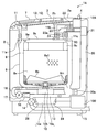
- FIG. 16 is an external perspective view of a washing machine (washing / drying machine) according to the third embodiment
- FIG. 17 is a schematic diagram showing an internal configuration of the washing machine (washing / drying machine) according to the third embodiment
- FIG. The top view which shows arrangement
- FIG. 19 shows the waterway member provided in an outer tank cover
- (a) is a front view
- FIG. 20 is a plan view
- FIG. 20 is a plan view showing the arrangement of waterway members provided on the front side of the washing machine (washing and drying machine) according to the third embodiment, and FIG. Shows the rear channel member of the washing machine (washing and drying machine) according to the third embodiment, (a) is a front view, (b) is a rear view, and FIG. 22 is a washing machine (washing) according to the third embodiment.
- FIG. 23 is an enlarged cross-sectional view showing the flow of water by the water channel member on the front side of the dryer
- FIG. Enlarged cross-sectional view showing the flow of water by waterway member on the rear side of FIG. 24 is a schematic diagram showing the overall flow of water when the tank cleaning of the washing machine (washing and drying machine) according to the third embodiment.
- the washing / drying machine 1C of the third embodiment is a drum-type washing / drying machine, and includes a housing 2A, a rotating drum (inner tank) 8A (see FIG. 17) indicated by a broken line, and an outer tank 9A.
- a housing 2A a rotating drum (inner tank) 8A (see FIG. 17) indicated by a broken line, and an outer tank 9A.
- water channel members 50A and 50B water supply path
- a drive device 10A drive device, see FIG. 17
- an operation panel 7A is provided on the housing 2A.
- the water channel members 50A and 50B are supplied with water from the water supply unit 12C via the branch hoses 11c1 and 11c2, respectively (see FIG. 24).
- the casing 2A is configured such that the outer shell is combined with a steel plate and a resin molded product and attached to the base Bs.
- a door 3A that closes an insertion port for taking in and out clothes (laundry, dry objects) is supported to be openable and closable.
- a door release button 3a for releasing a lock mechanism (not shown) of the door 3A is provided.
- a power switch 6A for turning on / off the power is provided on the right side of the operation panel 7A.
- a pull-out tray F1 into which a detergent, a softening agent and the like are charged
- a pull-out type dry filter F2 is provided on the right side of the operation panel 7A.
- the drying filter F2 includes a mesh type filter, and lint and dust are removed during the drying operation.
- a water supply hose connection port 4A connected to a water tap and a water absorption hose connection port 5A to which a hose for pumping up remaining hot water of a bath is connected are provided on the upper surface of the housing 2A.
- the rotating drum 8A (inner tub) indicated by a broken line is provided in the housing 2A and functions as a cylindrical washing / dehydrating tub that is rotatably supported.
- the rotary drum 8A has an opening 8d for putting clothes in and out on the front (front) end face, and a large number of through holes 8a1 (FIG. 5) for water flow and ventilation on the peripheral wall and bottom wall (back side). 22 and FIG. 23).
- a balance ring 8e integrated with the rotary drum 8A is provided at the edge of the opening 8d.
- the inner peripheral wall of the rotary drum 8A is provided with a plurality of lifters 8f extending in the depth direction (axial direction).
- the outer tub 9A encloses the rotating drum 8A coaxially and is formed in a cylindrical shape with an open front surface, and the inside functions as a washing room and a drying room.
- a synthetic resin-made outer tank cover 9h is provided in the opening on the front surface of the outer tank 9A, and water can be stored in the outer tank 9A.
- An opening 9h1 for taking in and out clothing and the like is formed at the center of the front side (near side) of the outer tub cover 9h.
- the opening 9h1 and the opening provided in the reinforcing member (not shown) are connected by rubber packing. This packing plays the role of maintaining the watertightness of the outer tub 9A and the door 3A. This prevents water leakage during washing, rinsing and dehydration.
- a drain port 9i is provided on the bottom surface of the outer tub 9A, and a drain hose H is connected thereto.
- the lower part of the outer tub 9A is supported by a plurality of vibration isolating means F3 (configured by coil springs and dampers) whose lower side is fixed to the base Bs.
- the upper portion of the outer tub 9A is supported by an auxiliary spring (not shown) attached to the upper reinforcing member, and is configured to prevent the outer tub 9A from falling in the front-rear direction.
- a drain valve 14A is provided in the middle of the drain hose H. By closing the drain valve 14A and supplying water, water is stored in the outer tub 9A, and by opening the drain valve 14A, water in the outer tub 9A is drained. It is discharged outside the machine.
- the driving device 10A is for rotating the rotary drum 8A, and is provided at the center of the back surface of the outer tub 9A.
- the rotating shaft 10g of the driving device 10A passes through the outer tub 9A and is coupled to a metal flange 10h provided on the back surface of the rotating drum 8A.
- the washing / drying machine 1C includes a blower duct (fan passage) 20A inside the housing 2A.
- the blower duct 20A has a rear duct 20b that extends in the vertical direction (vertical direction) on the back side of the outer tub 9A, and an upper duct 20c that extends from the rear to the front on the upper surface side of the outer tub 9A.
- an outlet 9j provided in the lower back part of the outer tub 9A is connected substantially horizontally via a bellows 20d having a flexible structure.
- a water-cooled dehumidifying mechanism (not shown) is provided in the rear duct 20b.
- a blower fan unit including a fan 21A as a blower and a heater 22A as a heater is provided on the downstream side of the upper duct 20c.
- air is taken into the blower fan unit from the upper duct 20c by the suction force of the fan 21A, and the taken-in air is heated by passing through the heater 22A. It is discharged from (not shown). Further, when air passes through the rear duct 20b, it is cooled by a water-cooled dehumidifying mechanism (not shown) to perform dehumidification.
- the heated air discharged from the blower fan unit is supplied into the rotary drum 8A through the hot air duct 20k, the bellows 20l, and the blowing nozzle 20m.
- FIG. 18 shows the outer tub cover 9h as viewed from the inside.
- a water channel member 50A for sprinkling tap water for tank cleaning is attached to the outer tank cover 9h (the front side of the outer tank 9A).
- the water channel member 50A has a substantially arcuate shape (arc shape) and is disposed along the circumferential direction on the upper surface of the inner surface 9k of the outer tub cover 9h, in other words, along the circumferential direction of the rotary drum 8A (see FIG. 17).
- the water channel member 50A is formed with a length of about a quarter of the circumference, and is disposed so as to extend from the center to the left and right with the same length.
- a plurality of water spray ports 50b2 are formed on the front surface (side surface) 50d of the water channel member 50A at intervals in the circumferential direction.
- nine sprinkling ports 50b2 are formed, but the number may be less than nine or may be ten or more.
- a water supply port 50f1 is formed at the center in the length direction on the upper surface 50e of the water channel member 50A.
- water spouts 50c2 are formed at the left and right ends of the water channel member 50A.
- the water spout 50c2 is configured to spray water to the left and right sides.
- a plurality of mounting portions 51A are formed on the upper surface 50e of the water channel member 50A so as to protrude rearward at intervals in the circumferential direction.
- the mounting portion 51A has a rectangular piece 51a, and is configured by forming a screw insertion hole 51b in the piece 51a.
- Each attachment portion 51 is formed to be flush with the upper surface 50e.
- a water spray port 50a2 is formed on the bottom surface 50f of the water channel member 50A at a position facing the water supply port 50f1.
- only one water spout 50a2 is provided, but it may be provided at a plurality of locations.
- FIG. 20 shows a state in which the inside of the outer tub 9A with the outer tub cover 9h removed is viewed from the front side (front side).
- a water channel member 50 ⁇ / b> B for sprinkling tap water for tank cleaning is attached to the bottom surface (back surface) 9 t of the outer tank 9 ⁇ / b> A.
- the water channel member 50B has a substantially arcuate shape (arc shape), and extends along the circumferential direction on the upper surface of the bottom surface 9t (back surface) of the outer tub 9A, in other words, the circumferential direction of the rotating drum 8A (see FIG. 17). Are arranged along. Further, the water channel member 50B is formed with a length of about a quarter of the circumference, and is disposed so as to extend from the center to the left and right with the same length.
- water spouts 50b3 and 50b3 are formed on the front surface (side surface) 50g of the water channel member 50B. Further, the water channel member 50B has mounting portions 51B formed on its upper and lower surfaces alternately spaced in the circumferential direction.
- the mounting portion 51B has a rectangular piece 51a, and is configured by forming a screw insertion hole 51b in the piece 51a.
- a plurality of water spray ports 50b4 are formed at intervals in the circumferential direction on the back surface (side surface) 50h of the water channel member 50B.
- the water spout 50b4 is formed at intervals in the circumferential direction of the water channel member 50B.
- the mounting portion 51B of the water channel member 50B is formed flush with the back surface 50h.
- each process is executed in the same manner as in the first embodiment. That is, with the tap water stored in the outer tub 9A, the rotary drum 8A is rotated at a rotational speed (80 to 130 rpm) that is higher than the rotational speed during washing and lower than the rotational speed during dehydration.
- the channel member 50A is disposed in the outer tub cover 9h so as to extend in the circumferential direction of the rotary drum 8A (the back side and the near side in the drawing).
- the outer tub cover 9h in the present embodiment is disposed so as to cover the peripheral surface of the balance ring 8e at the front end of the rotating drum 8A, and has an inclined surface 9h2 that decreases in diameter toward the front side.
- the body plate of the rotating drum 8A has a throttle portion 8v whose diameter is reduced at the position of the water channel member 50A, and a balance ring 8e is attached to the throttle portion 8v.
- the water supply port 50f1 of the water channel member 50A penetrates the outer tank cover 9h and protrudes upward from the outer tank cover 9h. Tap water is supplied to the water supply port 50f1 from a water supply unit (not shown) via a hose.
- water is sprayed from the water spout 50b2 formed on the front surface 50d of the water channel member 50A toward the inner peripheral surface 9s of the outer tank cover 9h (outer tank 9A).
- the tap water sprayed on the inner peripheral surface 9s flows down on the surface of the inner peripheral surface 9s of the outer tub cover 9h by the action of gravity, as indicated by solid arrows.
- water is sprinkled from the water spout 50a2 formed on the bottom surface 50f of the water channel member 50A to the upper part (squeezed part 8v) of the rotating drum 8A as shown by the solid line arrow.
- the tap water sprayed on the throttle portion 8v scatters to the inner peripheral surface 9s of the outer tub cover 9h (outer tub 9A) by the centrifugal force of the rotary drum 8A. Splatters on the outer peripheral surface 8s and flows backward.
- the water channel member 50B is disposed on the bottom surface 9t of the outer tub 9A so as to extend in the circumferential direction of the rotary drum 8A (the back side and the front side in the drawing). Further, the water channel member 50B is disposed so that a gap is formed between the back surface 50h and the bottom surface 9t so that water can be sprayed from the water spray port 50b4 to the bottom surface 9t.
- an annular flange portion 8t1 protrudes rearward from the outer peripheral edge portion of the bottom surface 8t, and a synthetic resin bottom plate 8u is fixed in the flange portion 8t1.
- tap water is sprinkled from the water spout 50b4 formed on the back surface 50h of the water channel member 50B toward the bottom surface 9t of the outer tub 9A as indicated by the solid line arrow.
- the tap water sprayed on the bottom surface 9t flows downward by the action of gravity.
- water is sprayed from the sprinkling ports 50b3, 50b3 (see FIGS. 20 and 21) formed on the front surface 50g of the water channel member 50B toward the bottom plate 8u of the rotating drum 8A as indicated by broken line arrows.
- the tap water sprayed on the bottom plate 8u is sprayed on the entire outer peripheral surface of the bottom plate 8u as the rotating drum 8A rotates.
- the water channel member 50A has a plurality of water spray ports 50b2 sprayed toward the inner peripheral surface 9s of the outer tank cover 9h along the circumferential direction.
- the tap water thus made flows down downward in the vertical direction on the inner peripheral surface 9s of the outer tub cover 9h by the action of gravity.
- the inner peripheral surfaces 9s at the left and right end portions of the outer tank cover 9h Even water can be sprinkled. Therefore, it becomes possible to flow tap water over the entire inner peripheral surface of the outer tub cover 9h.
- the water channel member 50A is formed with a water spout 50a2 sprinkled toward the upper front end of the rotary drum 8A, the tap water sprinkled from the water spout 50a2 is throttled by the centrifugal force of the rotary drum 8A. It can be scattered toward the inner peripheral surface 9s of the outer tub 9A facing the portion 8v.
- the water channel member 50B is formed with water spouts 50b3 and 50b3 that sprinkle toward the bottom surface 8t side (bottom plate 8u, see FIG. 22) of the rotating drum 8A.
- the water is sprayed over the entire outer periphery of the bottom plate 8u as the rotating drum 8A rotates.
- the water channel member 50B is formed with a plurality of water spouts 50b4 that sprinkle toward the bottom surface 9t (see FIG. 23) of the outer tub 9A, the tap water sprinkled from the water spout 50b4 to the bottom surface 9t is
- the bottom surface 9t of the outer tub 9A flows down from the upper part to the lower part by the action of gravity. Therefore, it becomes possible to flow tap water over the entire bottom surface 9t of the outer tub 9A.
- the process shown in FIG. 11 is executed in the same manner as in the first embodiment.
- rinse water clean water
- the rotary drum 8A is rotated to collect the water. Water is scooped up, and the inner peripheral surface of the outer tub 9A around the rotating drum 8A is cleaned.
- the outer tub cover 9h (outer tub 9A) is provided with the water channel member 50A (water supply path) extending in the circumferential direction of the rotary drum 8A.
- the member 50A is provided with a water spray port 50b2 for spraying tap water supplied from a water supply unit (not shown) to the inner peripheral surface 9s of the outer tank cover 9h (see FIG. 22).
- the throttle portion 8v rotary drum 8A
- Dirt and dust adhering to the outer peripheral surface can be removed, and adhesion of dirt and dust can be suppressed.
- the bottom plate 8u (rotating drum 8A) since the water channel member 50B in which the water spout 50b3 for spraying water is formed on the bottom plate 8u (rotating drum 8A) is provided (see FIG. 23), the bottom plate 8u (rotating drum 8A) is attached. Dirt and dust can be removed, and adhesion of dirt and dust can be suppressed.
- the water channel member 50B in which the water spout 50b4 which sprinkles water is formed in the bottom face 9t of the outer tank 9A is provided (refer FIG. 23), it adhered to the bottom face 9t (outer tank 9A). Dirt and dust can be removed, and adhesion of dirt and dust can be suppressed.
- through holes 8a1 formed in the body plate 8a of the washing and dewatering tub 8 of the washing / drying machines 1A and 1B) In the dewatering hole
- the group of through holes 8a1 located in the upper stage and the group of through holes 8a1 located in the lower stage may be arranged so as to overlap in the vertical direction. According to this, the water discharged from the through hole 8a1 located in the upper stage during dehydration and the water discharged from the through hole 8a1 located in the lower stage partially overlap and are discharged to the outer tank 9.
- the washing and dewatering tub 8 is described using the vertical washing dryer having the rotation axis of the substantially vertical direction, and the washing machine according to the third embodiment.
- the rotary drum has been described using the drum-type washing / drying machine 1C in which the rotation axis is substantially horizontal.
- the present invention is not limited thereto, and the vertical washing machine and the drum have no drying function. It may be a type washing machine.
Landscapes
- Engineering & Computer Science (AREA)
- Textile Engineering (AREA)
- Mechanical Engineering (AREA)
- Detail Structures Of Washing Machines And Dryers (AREA)
Abstract
Priority Applications (2)
| Application Number | Priority Date | Filing Date | Title |
|---|---|---|---|
| CN201280019207.2A CN103547725B (zh) | 2011-04-19 | 2012-02-20 | 洗衣机 |
| KR20137022853A KR101492499B1 (ko) | 2011-04-19 | 2012-02-20 | 세탁기 |
Applications Claiming Priority (2)
| Application Number | Priority Date | Filing Date | Title |
|---|---|---|---|
| JP2011-093460 | 2011-04-19 | ||
| JP2011093460A JP5785764B2 (ja) | 2011-04-19 | 2011-04-19 | 洗濯機 |
Publications (1)
| Publication Number | Publication Date |
|---|---|
| WO2012144262A1 true WO2012144262A1 (fr) | 2012-10-26 |
Family
ID=47041385
Family Applications (1)
| Application Number | Title | Priority Date | Filing Date |
|---|---|---|---|
| PCT/JP2012/054014 Ceased WO2012144262A1 (fr) | 2011-04-19 | 2012-02-20 | Machine à laver |
Country Status (4)
| Country | Link |
|---|---|
| JP (1) | JP5785764B2 (fr) |
| KR (1) | KR101492499B1 (fr) |
| CN (2) | CN105734886B (fr) |
| WO (1) | WO2012144262A1 (fr) |
Cited By (1)
| Publication number | Priority date | Publication date | Assignee | Title |
|---|---|---|---|---|
| CN119956592A (zh) * | 2025-01-24 | 2025-05-09 | 珠海格力电器股份有限公司 | 一种织物处理设备及织物处理设备的滤网脏堵处理方法 |
Families Citing this family (8)
| Publication number | Priority date | Publication date | Assignee | Title |
|---|---|---|---|---|
| CN106319865B (zh) * | 2015-07-07 | 2021-03-26 | 青岛海尔洗涤电器有限公司 | 一种洗衣机及控制方法 |
| KR102522794B1 (ko) * | 2016-02-01 | 2023-04-19 | 엘지전자 주식회사 | 드럼 세탁기 및 드럼 세탁기의 터브 세척 방법 |
| US11326292B2 (en) | 2016-02-01 | 2022-05-10 | Lg Electronics Inc. | Drum washing machine and method for cleaning tub thereof |
| CN108252029A (zh) * | 2016-12-29 | 2018-07-06 | 青岛海尔洗衣机有限公司 | 可清洗洗衣机内外桶的外桶盖及洗衣机 |
| WO2019027295A1 (fr) | 2017-08-04 | 2019-02-07 | Samsung Electronics Co., Ltd. | Lave-linge |
| CN111286925B (zh) * | 2018-12-10 | 2022-05-31 | 无锡小天鹅电器有限公司 | 衣物处理设备、用于衣物处理设备的平衡环 |
| KR102664420B1 (ko) * | 2019-06-28 | 2024-05-08 | 엘지전자 주식회사 | 의류처리장치의 제어방법 |
| CN115074944B (zh) * | 2021-03-10 | 2025-07-04 | 无锡小天鹅电器有限公司 | 一种桶盖、筒体组件及衣物处理设备 |
Citations (3)
| Publication number | Priority date | Publication date | Assignee | Title |
|---|---|---|---|---|
| JPH08299679A (ja) * | 1995-04-28 | 1996-11-19 | Matsushita Electric Ind Co Ltd | 洗濯機 |
| JPH09786A (ja) * | 1995-04-29 | 1997-01-07 | Daewoo Electronics Co Ltd | 噴射ノズル組立体を具備した洗濯機 |
| JP2006239141A (ja) * | 2005-03-03 | 2006-09-14 | Sharp Corp | ドラム式洗濯機 |
Family Cites Families (3)
| Publication number | Priority date | Publication date | Assignee | Title |
|---|---|---|---|---|
| JPH07273843A (ja) * | 1994-03-25 | 1995-10-20 | Nec Corp | 携帯無線機の着信通報方法及び通報装置 |
| US6205603B1 (en) * | 1997-12-19 | 2001-03-27 | Maytag Corporation | Front water injection for front loading washing machine |
| JP2008259665A (ja) * | 2007-04-12 | 2008-10-30 | Sharp Corp | ドラム式洗濯乾燥機 |
-
2011
- 2011-04-19 JP JP2011093460A patent/JP5785764B2/ja active Active
-
2012
- 2012-02-20 WO PCT/JP2012/054014 patent/WO2012144262A1/fr not_active Ceased
- 2012-02-20 CN CN201610206019.0A patent/CN105734886B/zh active Active
- 2012-02-20 KR KR20137022853A patent/KR101492499B1/ko not_active Expired - Fee Related
- 2012-02-20 CN CN201280019207.2A patent/CN103547725B/zh active Active
Patent Citations (3)
| Publication number | Priority date | Publication date | Assignee | Title |
|---|---|---|---|---|
| JPH08299679A (ja) * | 1995-04-28 | 1996-11-19 | Matsushita Electric Ind Co Ltd | 洗濯機 |
| JPH09786A (ja) * | 1995-04-29 | 1997-01-07 | Daewoo Electronics Co Ltd | 噴射ノズル組立体を具備した洗濯機 |
| JP2006239141A (ja) * | 2005-03-03 | 2006-09-14 | Sharp Corp | ドラム式洗濯機 |
Cited By (1)
| Publication number | Priority date | Publication date | Assignee | Title |
|---|---|---|---|---|
| CN119956592A (zh) * | 2025-01-24 | 2025-05-09 | 珠海格力电器股份有限公司 | 一种织物处理设备及织物处理设备的滤网脏堵处理方法 |
Also Published As
| Publication number | Publication date |
|---|---|
| CN105734886B (zh) | 2017-11-17 |
| KR20130129433A (ko) | 2013-11-28 |
| CN103547725B (zh) | 2016-05-04 |
| CN105734886A (zh) | 2016-07-06 |
| KR101492499B1 (ko) | 2015-02-11 |
| CN103547725A (zh) | 2014-01-29 |
| JP5785764B2 (ja) | 2015-09-30 |
| JP2012223359A (ja) | 2012-11-15 |
Similar Documents
| Publication | Publication Date | Title |
|---|---|---|
| JP5785764B2 (ja) | 洗濯機 | |
| CN103492628B (zh) | 洗衣机 | |
| JP5771728B2 (ja) | 洗濯機 | |
| WO2012144264A1 (fr) | Machine à laver à tambour | |
| JP2014083138A (ja) | 洗濯乾燥機 | |
| JP5743720B2 (ja) | 洗濯機 | |
| JP2014140777A (ja) | ドラム式洗濯機 | |
| JP5740518B2 (ja) | 洗濯機 | |
| JP5907673B2 (ja) | 洗濯機 | |
| JP2013226337A (ja) | 洗濯機 | |
| JP2014210007A (ja) | 洗濯機 | |
| JP5663688B2 (ja) | 洗濯機 | |
| JP5326034B2 (ja) | 洗濯機 | |
| JP5276753B2 (ja) | 洗濯機 | |
| JP5559112B2 (ja) | ドラム式洗濯機 | |
| JP6108567B2 (ja) | 洗濯機 | |
| JP5398932B2 (ja) | 洗濯機および縦型洗濯機 | |
| JP2013223552A (ja) | 洗濯機 | |
| JP2013039211A (ja) | ドラム式洗濯機 | |
| JP2015062509A (ja) | ドラム式洗濯機 | |
| JP5882396B2 (ja) | ドラム式洗濯機 | |
| JP2013070720A (ja) | ドラム式洗濯機 | |
| JP5894886B2 (ja) | 洗濯機 | |
| JP2012249723A (ja) | 洗濯機 | |
| JP5899355B2 (ja) | ドラム式洗濯機 |
Legal Events
| Date | Code | Title | Description |
|---|---|---|---|
| WWE | Wipo information: entry into national phase |
Ref document number: 201280019207.2 Country of ref document: CN |
|
| 121 | Ep: the epo has been informed by wipo that ep was designated in this application |
Ref document number: 12774478 Country of ref document: EP Kind code of ref document: A1 |
|
| DPE1 | Request for preliminary examination filed after expiration of 19th month from priority date (pct application filed from 20040101) | ||
| ENP | Entry into the national phase |
Ref document number: 20137022853 Country of ref document: KR Kind code of ref document: A |
|
| NENP | Non-entry into the national phase |
Ref country code: DE |
|
| 122 | Ep: pct application non-entry in european phase |
Ref document number: 12774478 Country of ref document: EP Kind code of ref document: A1 |